MicroNet SP5582HTM User manual
Micronet SP5582HTM
Micronet SP5582HTM
Full HD Vandal Dome IP Camera
User Manual
Ver1.0

1
Table of Contents
1. Introduction............................................................................................................................. 3
1.1 Features ........................................................................................................................3
1.2 Package Contents ......................................................................................................... 4
2. Introduction............................................................................................................................. 5
2. Introduction............................................................................................................................. 5
2.1 Dimensions.................................................................................................................... 5
2.2 Connectors .................................................................................................................... 6
3. Installation............................................................................................................................... 7
3.1 Power and Ethernet Cable Connection ......................................................................... 7
3.2 Hard Ceiling................................................................................................................... 8
3.3 4S Mount Electrical Box .............................................................................................. 13
4. System Requirements .......................................................................................................... 16
5. Deleting the Existing DC Viewer.......................................................................................... 17
6. Configuration & Operation................................................................................................... 20
6.1 Browser-based Viewer ................................................................................................ 20
6.2 Home Page ................................................................................................................. 22
6.3 System Settings .......................................................................................................... 24
6.3.1 Host Name and System Time...................................................................... 25
6.3.2 Security........................................................................................................ 27
6.3.2.1 User ............................................................................................. 28
6.3.2.2 HTTPS ......................................................................................... 31
6.3.2.3 IP Filter......................................................................................... 36
6.3.2.4 IEEE 802.1X ................................................................................ 37
6.3.3 Network........................................................................................................ 39
6.3.3.1 Basic ............................................................................................ 40
6.3.3.2 QoS (Quality of Service) .............................................................. 43
6.3.3.3 SNMP (Simple Network Management Protocol).......................... 45
6.3.3.4 UPnP............................................................................................ 47
6.3.4 DDNS........................................................................................................... 50
6.3.5 Mail .............................................................................................................. 52
6.3.6 FTP.............................................................................................................. 53
6.3.7 HTTP ........................................................................................................... 54
6.3.8 Application ................................................................................................... 55
6.3.9 Motion Detection.......................................................................................... 60
6.3.10 Tampering.................................................................................................... 66
6.3.11 Storage Management .................................................................................. 69
6.3.12 Recording .................................................................................................... 72
6.3.13 File Location ................................................................................................ 73

2
6.3.14 Iris Adjustment............................................................................................. 74
6.3.15 View Log File ............................................................................................... 75
6.3.16 View User Information ................................................................................. 76
6.3.17 View Parameters ......................................................................................... 78
6.3.18 Factory Default ............................................................................................ 79
6.3.19 Software Version ......................................................................................... 80
6.3.20 Software Upgrade........................................................................................ 81
6.3.21 Maintenance ................................................................................................ 84
6.4 Video and Audio Streaming Settings........................................................................... 86
6.4.1 Video Resolution and Rotate Type.............................................................. 86
6.4.2 Video Compression ..................................................................................... 90
6.4.3 Video OCX Protocol..................................................................................... 92
6.4.4 Video Frame Skip ........................................................................................ 93
6.4.5 Video Mask.................................................................................................. 94
6.4.6 Audio Mode and Bit Rate Settings............................................................... 96
6.5 Camera Settings.......................................................................................................... 98
6.5.1 Exposure...................................................................................................... 99
6.5.2 White Balance............................................................................................ 101
6.5.3 Backlight .................................................................................................... 102
6.5.4 Brightness.................................................................................................. 102
6.5.5 Sharpness.................................................................................................. 102
6.5.6 Contrast ..................................................................................................... 102
6.5.7 Saturation .................................................................................................. 103
6.5.8 Hue ............................................................................................................ 103
6.5.9 TV System ................................................................................................. 103
6.6 Logout ....................................................................................................................... 104
Appendix A: Technical Specifications...................................................................................... 105
Appendix B: Internet Security Settings .................................................................................... 107
Appendix C: DC Viewer Download Procedure......................................................................... 111
Appendix D: Install UPnP Components.................................................................................... 113
Appendix E: IP Scan Utility........................................................................................................ 116

3
1. Introduction
Micronet SP5582HTM Full HD Vandal Proof Dome IP Camera is capable of
serving real-time streaming and makes image quality more smoothly. In addition
to MJPEG real time streaming, this camera develops H.264 codec to apply for
high resolution digital broadcast. Attributing to the IP Camera’s flexible platform,
the SP5582HTM is ideal for versatile surveillance projects demanding for
installation at any locations, including shops, stores, schools, banks, parking
lots, factories, streets and etc. With industrial grade vandal-proof design, the
SP5582HTM can protect the camera from heavy damage.
1.1 Features
Progressive Scan CMOS Sensor
Full HD 1080p Video Quality
H.264 and MJPEG compression
Day/Night (ICR)
Built-in IR LEDs
Weatherproof, IP66
Vandal Proof Dome Cover
BNC Analog Output
Micro SD support
ONVIF Conformance
Motion Detection
Privacy Masks

4
1.2 Package Contents
Please check the package contents listed below.
Full HD Vandal Proof
Dome IP Camera
DC Jack Cable
Power Terminal Block
Security Torx
Self Tapping Screws
(×4)
Plastic Screw Anchors
(×4)
Rubber Washers (×6)
CD
(bundled software and
documentation)
Quick Guide
5
2. Introduction
This chapter will provide the camera dimensions for reference before installation.
Definition of each connector on the camera’s PCB board will also be specified.
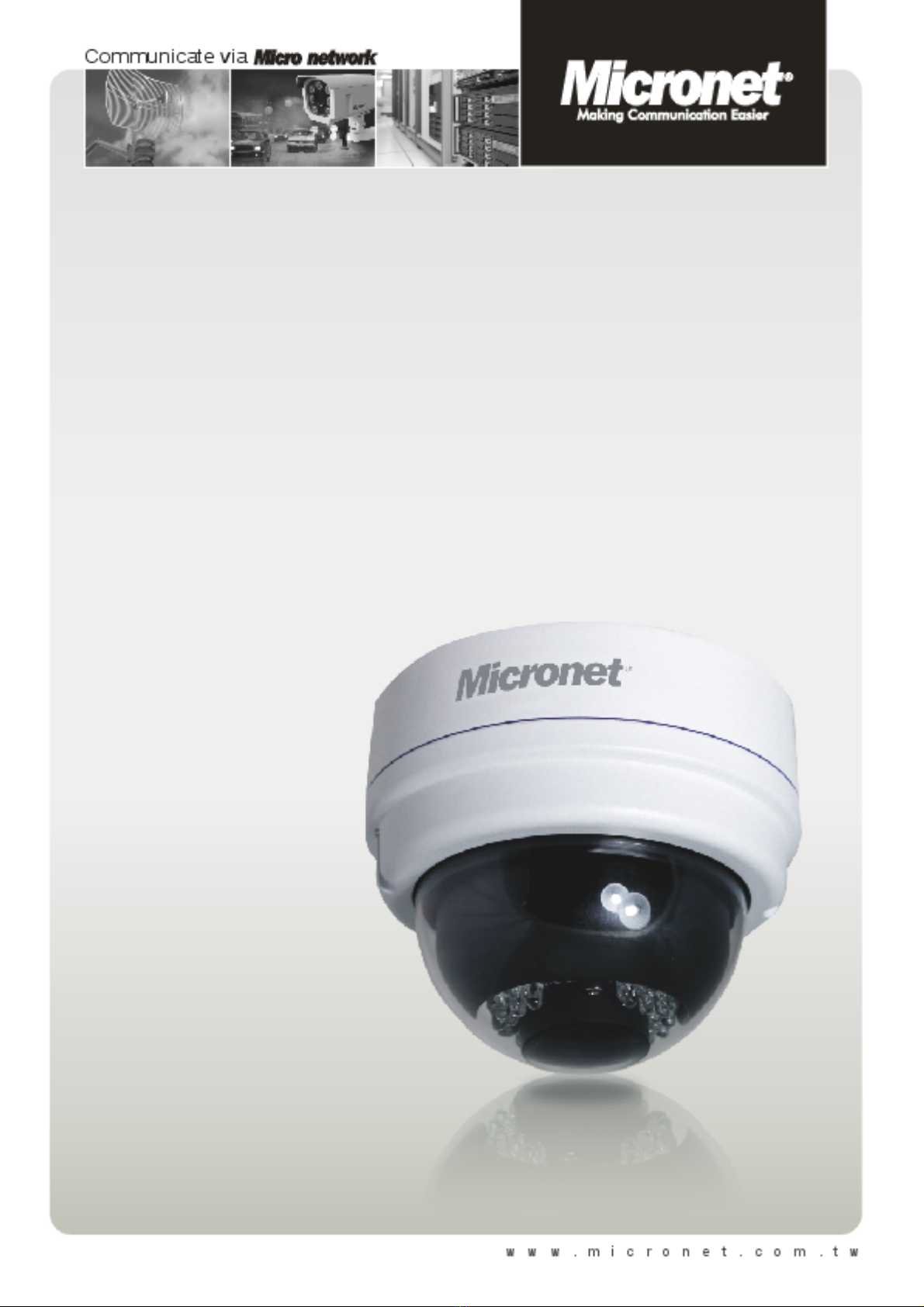
2.1 Dimensions
The Vandal Dome IP Camera’s dimensions are shown below.
Indoor
TopView Side View

6
2.2 Connectors

7
3. Installation
Please follow the instructions below to complete installation of the camera.
3.1 Power and Ethernet Cable Connection
Power Connection
Make sure the camera’s power cable is correctly and firmly connected; refer to
the pin definition table in section 2.2 Connectors. If using Power over Ethernet
(PoE), make sure Power Sourcing Equipment (PSE) is in use in the network.
Ethernet Cable Connection
Use of Category 5 Ethernet cable is recommended for network connection; to
have best transmission quality, cable length shall not exceed 100 meters.
Connect one end of the Ethernet cable to the RJ-45 connector of the IP Dome
Camera, and the other end of the cable to the network switch or PC.
NOTE: In some cases, you may need use an Ethernet crossover cable
when connecting the IP Dome Camera directly to the PC.
Check the status of the link indicator and activity indicator LEDs; if the LEDs are
unlit, please check LAN connection.
Green Link Light indicates good network connection.
Orange Activity Light flashes for network activity indication.

8
3.2 Hard Ceiling
The camera can be installed directly on a wall or ceiling. Please note that the
wall or ceiling must have enough strength to support the camera.
Follow the steps below to install the camera:
Step 1:
Unpack the camera package and take out the IP Dome Camera.
Step 2:
Use the supplied Security Torx to
unscrew the two Torx Screws on the
side of the Dome Cover, as shown in
the figure, and open the Dome
Cover.
Step 3:
Press both sides of the Inner Cover
and remove it from the Camera
Module.
Step 4:
Unscrew the Module-fastened
Screw, as indicated in the figure.
9
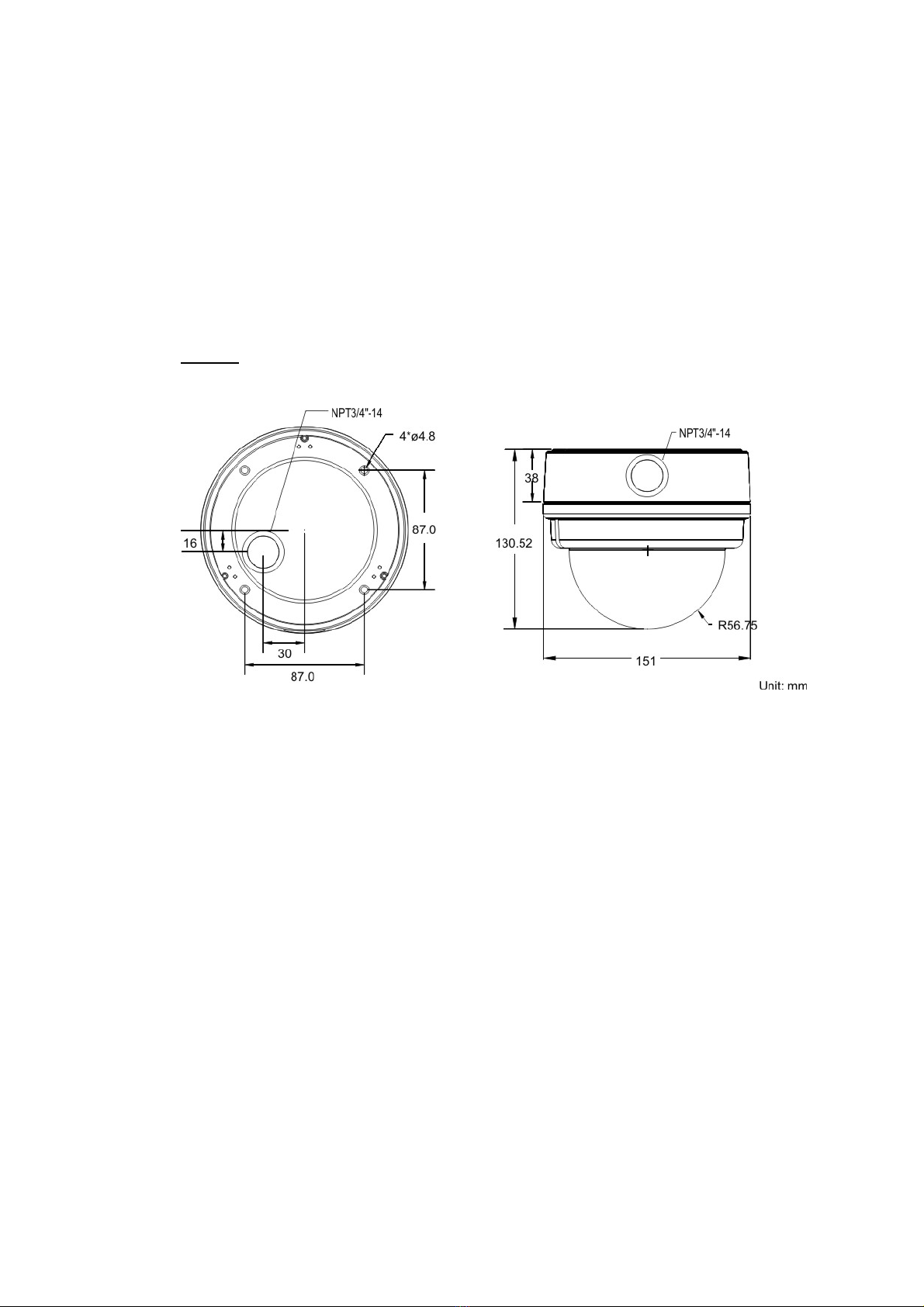
Step 5:
Press the sides of the Snap-on
Camera Module, as indicated in the
figure, and detach it from the Dome
Camera’s Housing.
Step 6:
Mark the positions of the four screw holes on the base of the Dome Camera
at the chosen installation location.
Step 7:
In the marked locations, drill each hole slightly smaller than the supplied
Screw Anchors.
Step 8:
Put supplied Anchors into these drilled holes.
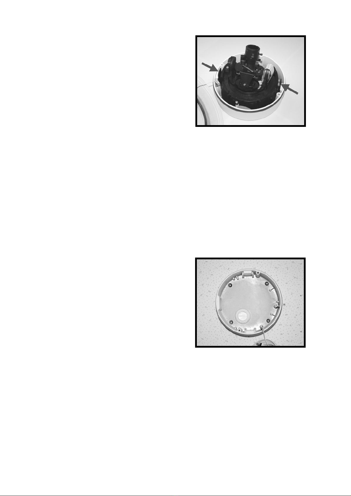
Step 9:
Fasten the Dome Camera’s Housing
with the four supplied Self-tapping
Screws.
Table of contents
Other MicroNet Security Camera manuals


