MICRONOR
automation components
Page
of
Table of Contents
1. Product Description ................................................................5
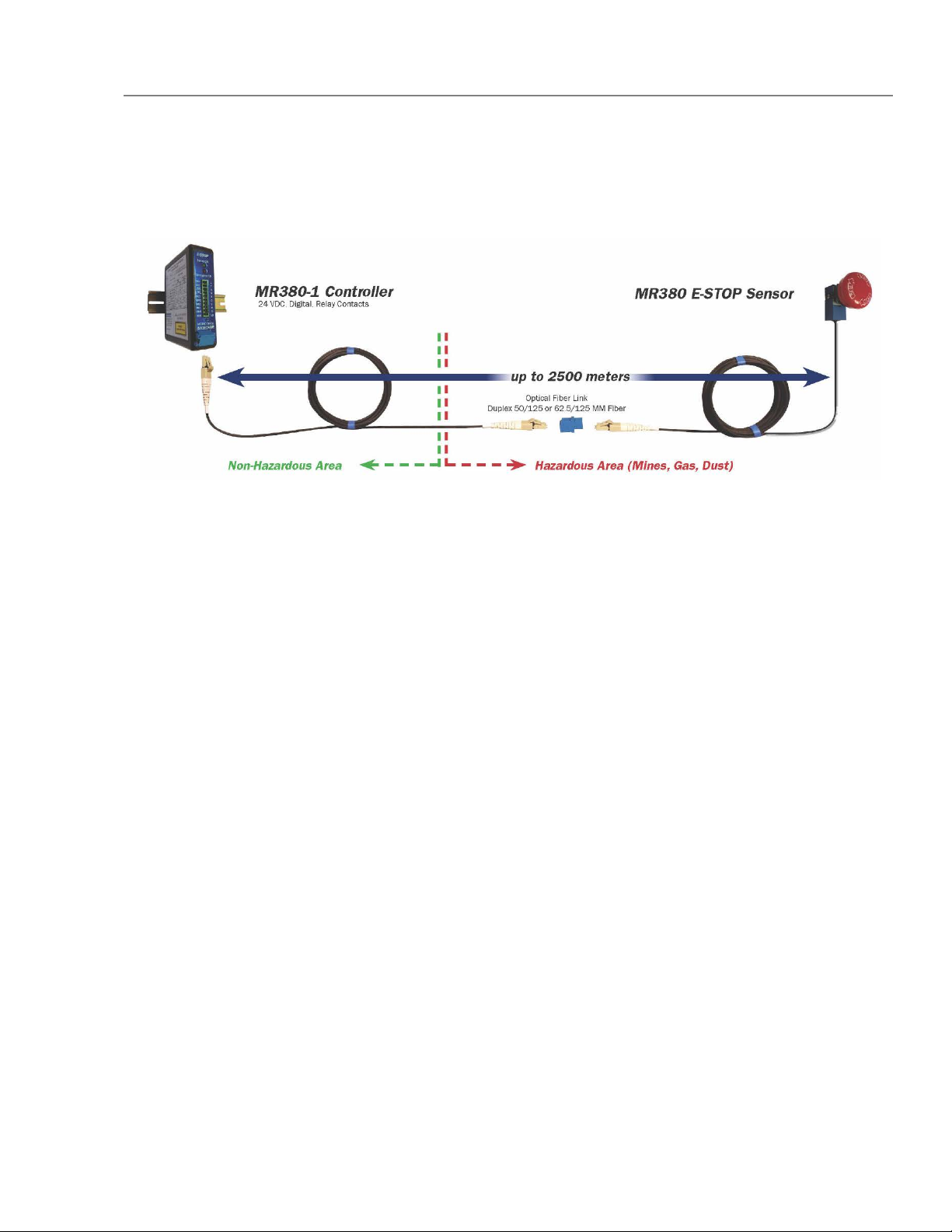
1.1. Fiber Optic Emergency Stop Switch ..................................................................................5
1.2. Fields of Application ...........................................................................................................6
1.3. Features..............................................................................................................................6
2. Standard Contents...................................................................7
3. Installation and Operation ......................................................8
3.1. Mounting the Emergency Switch.......................................................................................8
3.2. Mounting the Controller Module .......................................................................................9
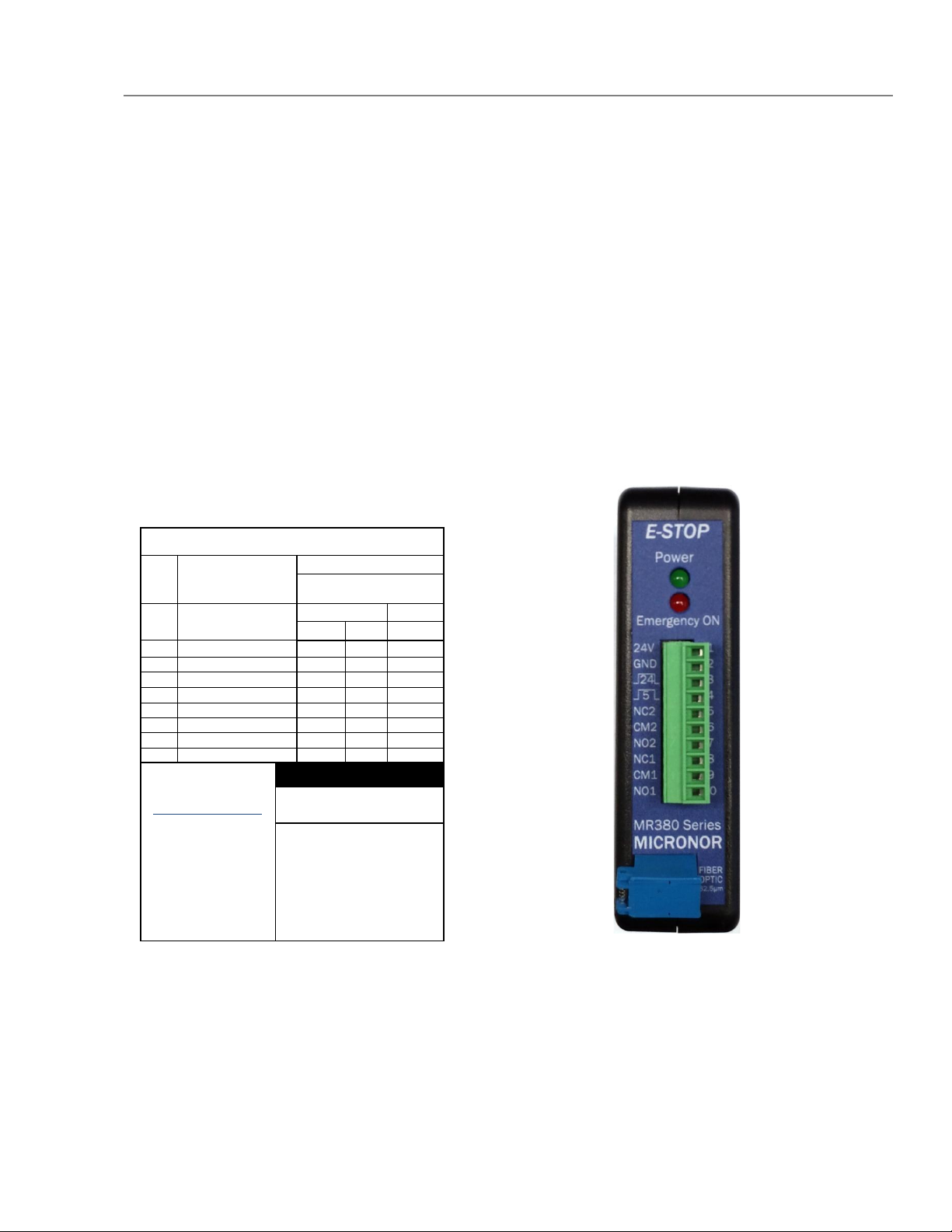
3.3. Connecting the Controller ................................................................................................10
3.4. System Start-Up & Performance Check..........................................................................11
4. Troubleshooting ....................................................................12
4.1. Potential Issues & Solutions............................................................................................12
4.1.1. ‘Power’ not illuminated when controller powered ..................................................12
4.1.2. ‘Emergency ON’ illuminated w/Emergency Switch Connected..............................12
4.1.3. No +24V Digital Out ..................................................................................................12
4.1.4. No +5V Digital Out ....................................................................................................12
4.1.5. Relay Switching Failure.............................................................................................13
4.1.6. Damaged Emergency Switch (Fiber)........................................................................13
4.2. Damaged In Shipment .....................................................................................................14
5. Warranty Information ............................................................15
6. Specifications ........................................................................16
6.1. E-STOP Sensor ..................................................................................................................16
6.2. E-STOP Controller Module................................................................................................18
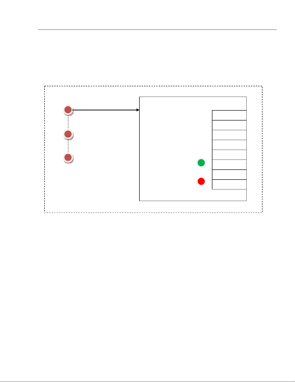
7. Theory of Operation ..............................................................20
8. Application Notes ..................................................................21
8.1. Determining System Loss Budget For Chaining Multiple Switches ..............................21
9. Mechanical Reference Drawings..........................................23
9.1. MR380-1 Controller .........................................................................................................23
9.2. MR382-2 Sensor ..............................................................................................................23