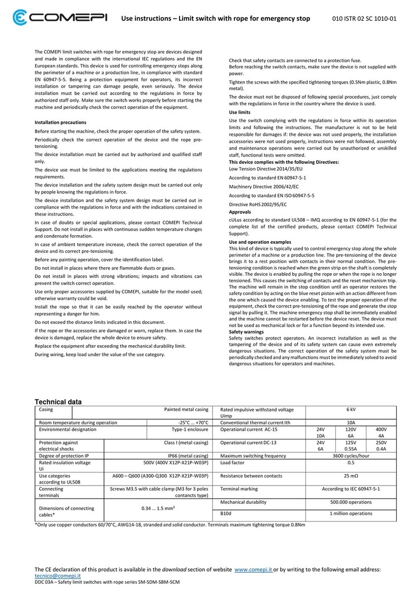
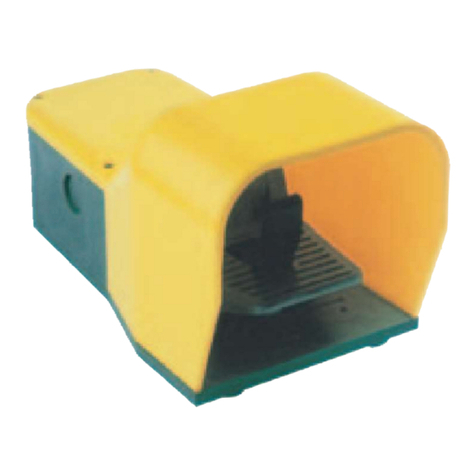
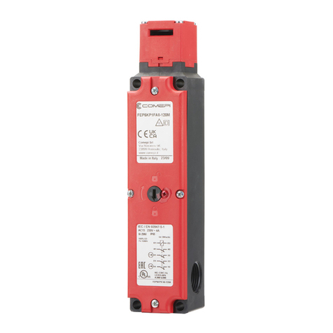
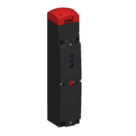
L’interruttore di finecorsa T80 è un dispositivo adatto monitorare in sicurezza le porte
automatiche in ascensori.
Costruzione del codice
Esempio: AP1T80J01
AP = 1 ingresso cavo filettato / DP = 2 ingressi cavo filettati
1 = PG13,5 / 2 = ½”NPT / 3 = PG11 / 4 = M16x1,5 / 5 = M20x1,5
T80 = Testina di attuazione per porte scorrevoli
J01 = Microinterruttore 1NC
Precauzioni di installazione
Prima della messa in funzione verificare il corretto funzionamento del sistema.
Verificare periodicamente il corretto funzionamento del dispositivo.
L’installazione deve essere eseguita solamente da personale autorizzato e qualificato.
L’uso del dispositivo deve essere limitato alle applicazioni conformi con i requisiti normativi.
L’installazione del dispositivo e la progettazione del sistema devono essere eseguite solamente
da persone che abbiano a conoscenza i riferimenti normativi.
L’istallazione del dispositivo e la progettazione del sistema devono essere eseguite in accordo
alle normative vigenti.
In caso di dubbi o applicazioni speciali contattare l’assistenza tecnica COMEPI.
Non installare in ambienti in cui vi sia presenza di polvere o sporcizia.
Prima di eventuali lavori di verniciatura coprire bene l’etichetta identificativa.
Non installare in ambienti con presenza di polveri o gas infiammabili.
Non installare in presenza di forti vibrazioni; Urti e vibrazioni possono infatti precludere il
corretto funzionamento dell’interruttore.
La temperatura ambiente non deve superare i +40°C e la sua media nelle 24 ore non deve
superare i +35°C. Il limite di temperatura minima è –5°C.
L’umidità relativa non deve superare il 50% alla massima temperatura di +40°C, la massima
umidità relativa può aumentare a temperature più basse (per esempio 90% a +20°C).
La temperatura di stoccaggio deve essere compresa tra -25°C e +55°C, per periodi limitati di
tempo (non superiori alle 24h) è consentito uno stoccaggio fino a +70°C.
Utilizzare il dispositivo ad un’altitudine massima di 2000m sul livello del mare.
In caso di danneggiamenti o usura del dispositivo, sostituire il dispositivo completo per garantire
il mantenimento delle condizioni di sicurezza.
Non tentare di sostituire o riparare il microinterruttore, in caso di rotture sostituire il dispositivo.
In caso di rottura o danneggiamento dell’azionatore, sostituire lo stesso.
Utilizzare soltanto azionatori idonei forniti da COMEPI.
Finecorsa e azionatore devono essere fissati in maniera inamovibile e l’allineamento delle parti
deve essere verificato prima della messa in servizio dell’impianto.
Sostituire l’apparecchio dopo aver superato il limite di durabilità meccanica.
Durante il cablaggio mantenere il carico sotto il valore della categoria di impiego.
Assicurare il collegamento dei contatti di sicurezza ad un fusibile di protezione.
Prima di accedere ai contatti dell’interruttore assicurarsi di aver tolto tensione al dispositivo.
Serrare le viti con le coppie raccomandata (0.5Nm).
Utilizzare pressa cavo o connettore idoneo al grado IP richiesto.
Richiudere il coperchio in maniera accurata dopo il cablaggio utilizzando una coppia di 0.5Nm per
serrare la vite di fissaggio.
Il dispositivo non richiede procedure di smaltimento particolari, si prega di attenersi agli usuali
regolamenti di smaltimento validi nel paese d’impiego.
Limiti di utilizzo
Utilizzare l’interruttore nel pieno rispetto delle norme di sicurezza vigenti, seguendo le istruzioni
e impiegandolo in modo conforme ai suoi limiti di funzionamento. In caso di impiego non
conforme, mancato rispetto delle istruzioni, montaggio e manutenzioni eseguite da persone non
autorizzate o non specializzate ed omissione delle prove funzionali, il costruttore viene escluso
da ogni responsabilità.
Il dispositivo è conforme ai requisiti delle Direttive:
Direttiva Bassa Tensione 2014/35/UE - Secondo la normativa IEC 60947-1 e IEC 60947-5-1
Direttiva LIFT 2014/33/UE - Secondo le normative EN 81-20 ed EN 81-50
Direttiva RoHS 2011/65/EU
Omologazioni
cULus (NKCR) –CB (EN 60947-5-1)
Esempi di applicazione e funzionamento
Questa tipologia di dispositivo trova applicazione nel controllo in sicurezza di porte automatiche
per ascensori. Il contatto NC è da intendersi in condizioni di porta chiusa ed azionatore inserito
nel dispositivo. L’azionatore deve essere fissato in maniera solidale ed inamovibile alla parte
scorrevole della porta, l’interruttore deve essere fissato in maniera solidale ed inamovibile alla
parte fissa della porta. L’apertura della porta provoca l’azionamento positivo del contatto
equipaggiato nel finecorsa, che si porterà in posizione di aperto. Una nuova chiusura della porta
riporterà il contatto del finecorsa in posizione di chiuso.
The T80 limit switch is a suitable device to safely monitor automatic doors in elevators.
Code construction
Example: AP1T80J01
AP = 1 threaded cable inlet / DP = 2 Threaded cable inlets
1 = PG13,5 / 2 = ½”NPT / 3 = PG11 / 4 = M16x1,5 / 5 = M20x1,5
T80 = Actuating head for sliding doors
J01 = 1NC micro switch
Installation precautions
Before starting the system, check the proper operation of the system.
Periodically check the correct operation of the device.
The device installation must be carried out by authorized and qualified staff only.
The device use must be limited to the applications meeting the regulations requirements.
The device installation and the system design must be carried out only by people knowing the
regulations in force.
The device installation and the system design must be carried out in compliance with the
regulations in force.
In case of doubts or special applications, please contact COMEPI Technical Support.
Do not install in dusty or dirty places.
Before any painting operation, cover the identification label.
Do not install in places where there are flammable dusts or gases.
Do not install in places with strong vibrations; impacts and vibrations can prevent the switch
correct operation.
Ambient air temperature does not exceed +40°C and its average over 24h does not exceed
+35°C and the lower limit is -5°C.
Relative humidity must not exceed 50% at the maximum temperature of + 40 ° C, the maximum
relative humidity may increase at lower temperatures (for example 90% at + 20 ° C)
The storage temperature must be between -25 ° C and + 55 ° C, for limited periods of time (not
exceeding 24h) storage up to + 70 ° C is allowed.
Use the device at maximum altitude of 2000m above sea level.
If the limit switch is damaged or worn, replace the whole device to ensure safety.
Do not try to replace or repair the micro switch, in case of damage substitute the whole device.
If the actuator is damaged or worn, replace it.
Use only suitable actuators supplied by COMEPI.
Both actuator and limit switch must be fixed immovably and the alignment between parts must
be verified before starting the whole system.
Replace the equipment after exceeding the mechanical durability limit.
During wiring, keep load under the value of the use category.
Check that safety contacts are connected to a protection fuse.
Before reaching the switch contacts, make sure the device is not supplied with
power.
Tighten the screws with the specified tightening torques (0.5Nm plastic, 0.8Nm metal).
Use only connectors and cable glands suitable for the IP protection degree required.
Closing the cover carefully after wiring operations, using a tightening torque of 0.5Nm.
The device must not be disposed of following special procedures, just comply with
the regulations in force in the country where the device is used.
Use limits
Use the switch complying with the regulations in force within its operation limits.
The manufacturer is not to be held responsible for damages if: the device was not
used properly, instructions were not followed, assembly and maintenance
operations were carried out by unauthorized or unskilled staff.
This device complies with the following Directives:
Low Voltage Directive 2014/35/UE –According to standard IEC 60947-5-1 and IEC 60947-5-1
LIFT Directive 2014/33/UE –According to standards EN 81-20 ed EN 81-50
Direttiva RoHS 2011/65/EU
Approvals
cULus (NKCR) –CB (EN 60947-5-1)
Use and operation examples
This type of device finds application in the safe control of automatic doors for lifts. The NC
contact is intended in conditions of closed door and actuator inserted in the device. The
actuator must be fixed integrally and immovably to the sliding part of the door, the switch must
be fixed integrally and immovably to the fixed part of the door. Opening the door causes the
positive activation of the contact equipped in the limit switch, which will move to the open
position. Closing the door again will return the limit switch contact to the closed position.


