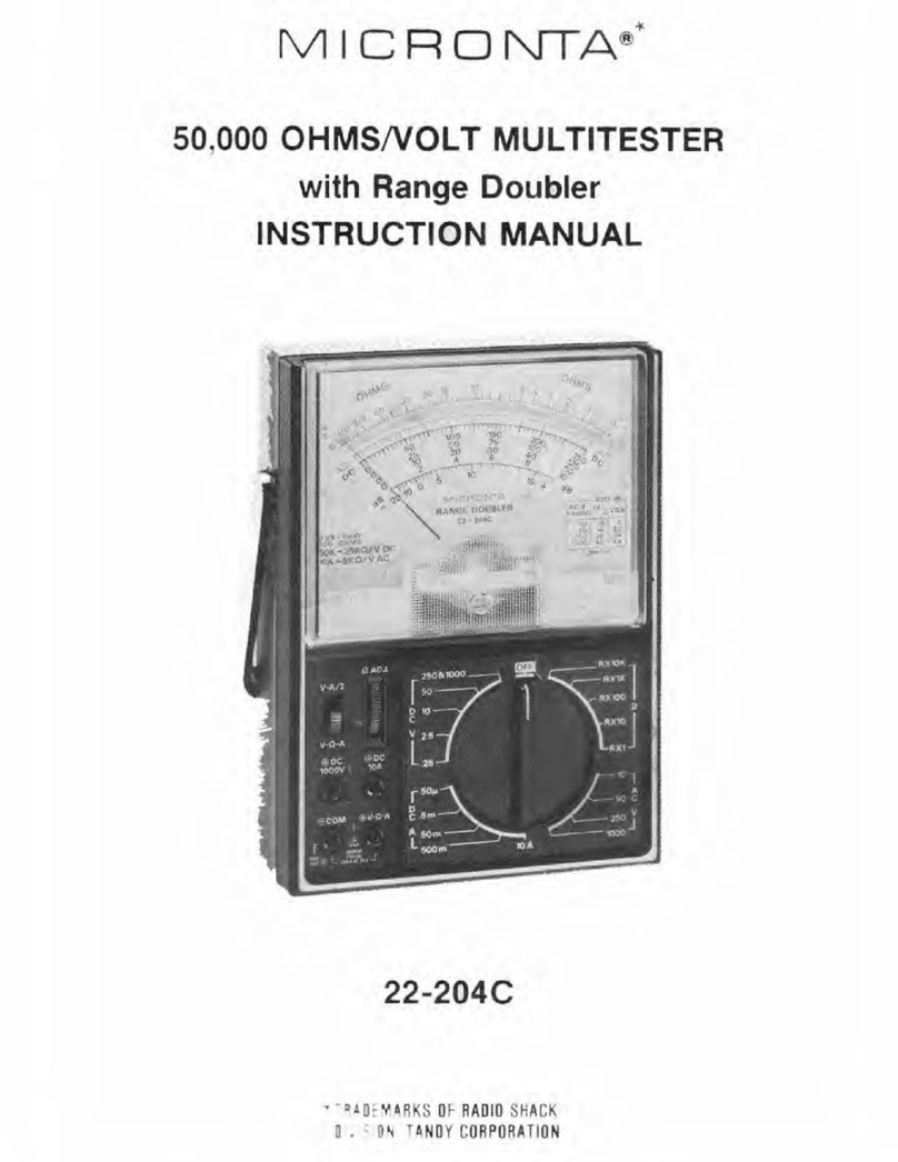
Micronta 22-211 User manual

MICRONTA:'
20.000
OHMS;VOLT
FOLDING
MU
LTITESTER
INSTRUCTION
MANUAL
CAT
.
N0.22-21
1
CU
STOM
MA
NUFAC
T
URED
FO
R
RAOIO
SHA
CK, A DIVISION
OF
TAN
OY
CORPO
R
ATIOI
SCHEMATIC DIAGRAM
6A9
"_
.
....
...................
..._......
.
::
.
~
.::
:·
·,
~:;:
~
:~:::~=~~·
.
":-~...::::~~
.
'
!..~.'.:
~~
·
::
...
;:;,-;;
""""'
..._....
..
~
---
......
- .'
i"
~·-
-
...,..
...
RADIO SKACK
A
Division
of
Tandy
Corporation
Fort
Worth,
Texas
76102
Printed
in
HONG
KONG
811012170C

INTRODUCTION
This
com
pact, sensitive Multitcster isdesigned
tomeasure
AC and
DC
voltages,
OC
current,
and
resis
tante
wîth
ac
·
curacy
and
ease.
The
single
knob
fu
nction
control
îs
easv
to
read and use.
The
4"
(10
cm}
meter
in
corpor
ates a
mirrored
scale
for
accurate readings and uses three colors f
or
rapid scale
id
entifica
ti
on.
The
meter movement is shunted,
for
protection,
du
ring
transit.
This
is accomplished automâtically every
time
the
Multites
te
r îs folded
shut.
The
meter
circuit i
ncorporates
a fuse
to
protect
the
de
licate
meter
movement
and
other
internai
parts
in case
of
inadvertent
overload
or
improper
function
selection.
The
operating
and indicating sections
are
connected
to
each
other
by
a hinge-joint wi
th
detent.
This
atlows
the
user
to
get
an
optimum
angle f
or
eas:y reading
in
ali operating
pos
i
tions
eîther
wh
en
portable
or
on
bench
top.
44"
(1
tO
cm)
weil insulated
test
lea~s
with
banana·
type
plugs
result
in firm, safe,
low
·resistance
circuit
con·
nections.
Small
and
light, this:
instrument
will
pr
ovîde
man
y
yea
rs
of
accurate voltage,
current
, and resistance meas
urement
s.
One
AA
cell provides
power
for
resistance measurement.
@
Copyright
1989
.
Tandy
Corporation
-2-
SPECIFICATIONS
Ranges:
OC Voltage
AC Voltage
OCCurrent
Resistance
Dec
ibels
Output
25
0
-0
.6-3-15-60-300-600-1
200V
0-15-60-150-60Q-1200V
0·60
!IA·3-3Q-300
mA
0·2K.
0·20K,
0-
200K
, 0-2Meg. (centec
sca
le
24)
-2
0
to
+
63
dB
in 5 ranges
0·15·60-150
-600
V
Accuracy
(at
horizontal
position):
±3%
of
full-scale, OC
voltageandcurrent
±4%
of
fuU-sc_ale, AC 110ltage
±3%
of
scale·length, Resistance
Influence
of
Scale Angle
(at
vertical position);
±2%
of
full scale
Sensitivity:
20,000
ohms/volt
DC
10,000
ohms
/voltAC
Meter
Movement:
Oetent:
Batt
cry:
leads:
Fuse:
Size:
Weight:
4"
(10
cm}, 3
-c
olor
, mirrored scale,
37
JJ.A
movement
90
, 120. 150,
180
degcees
Requires
one
type
AA penlight
ce
li
for
ohms:
functîon
44"'
(110cm)
banana-plug
styl
e
0.5A,
250V
fast·acting, 5.x20 mm
typ
e
7.3H x 4.4W x
1.30
inches
18.4H
x
ll.OW
x
3.30
cm
(tu
ll
y open)
4H
x
4.4W
x 2.SD inches
lO.OH x
11
,
OW
x 6.
30
cm
(fu
fly
closed)
350g(0.81b<.l
-
3-

TO
USE
The
fo
l!
owing special markings
are
designed
to
remind
you
of
safety.
&.Ref
er
to
the
followlng operating instructions.
@ To avold eleetrical shock and/or instrument damage
do
no
t connect
th
e
common
input
te
rm
inal
(-jack)
to
any
source
of
more than
500
volts with respect
to
earth/
ground.
Press latch on the front
of
case
to
open.
Remove
banery
cover
and
install
one
AA cell
tnot
sup-
plied).
We
recommend
our
23·582
or
23·552.
Be
sure
to
obserVe
proper
polarity. Close t
he
cover. ·
When
vou
can't adjust the pointer
to
"0"
on OHMS ra
ng«,
it's time for a new
battery.
Never leave a weak
or
de
ad
battery
in
your
uni
t. Even a " lea
k·proof"
battery
may
lea
k damaging chemicals. Also, if
vou
are
not
go
ing
to
use
your
unit
for
aweek
or
more, remove the battcry.
Notes:
For
most accurate readings, keep the me
ter
lyi
ng
f
la
t
on
a
non·me
ta
ll
ic surface.
Us
e a range
setting
that
re-
sul
ts
in a r
ead
ing in
th
e
upper
l/3rd
of
the
meter
scale.
Also, l
oo
k
at
th
e scale
from
the
point
where
the
poi
nt
er
and
its mi
rror
r
ef
l
ect
i
on
come
togethar;
ot
herwise y
our
reading
wi
ll
be inaccur
ate
due
to
para
ll
ax.
The poi
nte
r m
ay
shih slightly from
the
"0"
position as
y
ou
ch
ange
the
angle
of
the
meter
section.
-4-
1f the poi
nte
r does
not
normally rest
cxac
t
fy
over
th
e
"
0"
at
tk
e le
ft
side
of
the
scale,
adjuu
the
plastic screw
in
the
lo
wer
center
of
the
meter
face
to
bring
the
needle
!0 "0
."
Always observe
correc
t
test
lead polaritv
when
making
OC
voltage
and
current
measurements (Black in
to
the8
COM a
nd
Red
into
the0V
·n·A
or
OCSOOV
or
DC1200V
jacks).
CAUTION: THE MAXIMUM INPUT
LIMIT
FOR
VOLTAGE
AND
CURRENT MEASUAEMENT BE·
TWEEN 0
v.n.A
AND
8 COM
IS
600V AC,
300V OC
AND
300mA
OC.
TEST
LEAD
S
Use
only
the
same
type
of
tenlellds atthose
supplie<!
with
your
unit.
These
test
leads are rated for
1200
volts; replace-
ments
are
available from
your
local RadioShack
store.
OC
VOLTAGE
MEASUREMENTS
WARNING
~
US
E EXTREME CARE WHEN
MAK
·
ING MEASUREMENTS FOR HIGH VOLTAGE;
DO
NO
T TOUCH TERMI
NA
LSOR
PROBE
EN
DS
.
1. Plug t
he
te
st
leads i
nto
th
e
correct
jacks (Black into 8
COM
and
Red
i
nt
o 0 V
·n
·
AI.
2. Set
the
ra
ng
e switch
to
one
of
the
CCV pos
it
ion
s;
it
is ·
best
to
start
at t
he
top
and
w
ork
do
wn.
lf
you're
unce
rt
aln
about
voltage revel,
stan
with 1
20
0V
rangeas noted in st
ep
5.
-5-

3.
Touch
the
test
pmbe
tips
to
the
circuit 'Jnder test;
be
sure
to
observe correct polaritv.
4.
Rcad
the
voltage
on
the
black DC scales.
S. For voltages between
300
and
600.
set
the
range switch
ta
300&UP and plug the ted test lead into
the
DC600V
jack. For voltages between
600
and
1200.
leave
the
range
at
300&UP and
plug
the red
test
lead
into
the
DC1200V jatk.
USE
EXTREMECAREWHENUSING THESE RANGES.
AC
VOLTAGE
MEASUREMENTS
WARNING ) USE EXTREME CARE WHEN
MAK-
ING MEASUREMENTS FOR HIGH
VOLTAGE;
DO NOT TOUCH TERMINALS
OR
PROBE
ENDS.
1. Plug
the
test
leads
into
the
cor'rect jacks.
2.
Set
the range switch
to
one
of
the
ACV positions.
(lt
is best
to
start
at
the
top
and
work
dawn.)
If you're uncertain
about
voltage leve!, start with 1200V
range as noted in
step
5.
3. T
ouch
the
test probe tips
to
the
circuit
under
test.
4.
Read
the
voltage
on
the
red AC scales.
5.
For
voltages between
600
and
1200, set
the
rangeswitch
to
600&UP and plug
th
e red test lead ln
to
the
AC1200V
jack.
-6-
, RESISTANCE MEASUREMENTS
Before taking
any
resistance measurements, disconnect
the
power
to
the
unit
under
test
and discharge
the
capacitors.
1t
is best
to
remove batteries and unplug lîne cards.
WARNING t DO NOT APPLY VOLTAGE
TO
MEASURING TERMI
NAL
WH
ILE
RANGE SWITCH
IS
IN
OHM POSITION.
1. Plug the test
leads
into
the 8 COMand
(!)V.fl-Ajatks.
2.
Set
the
range switch
to
onè
·
of
the OHMS positions;
touch
the
test
probe
tips
to
.g
ether
and adjust
the
OHM
ADJ
UST
control
to
brîng
the
pointer
to
the
"0"
on
the
top
(green) OHMS scale.
3.
Now,
touch
the
probe tips across
the
circuit
or
part
under
test.
4.
Read
the
resistance
on
the green OHMS scale;
use
the
proper multiplier
to
obtain
the
co~rect
value (R times
1.
1
O.
100
,
or
1000, depending
on
the
position
of
the
range switch).
Notes: When you
are
unable
to
·adîust
the
pointer
to
"0"
on
the
OHMS scale, the
battery
must
be
replaced, When
measuring resistance,
it
is best
to
disconnect
one
side
of
the
part
und
er test.
(The-
remainder
of
the
circuit will
not
interferewith
the
r'eadings.)
Note
for Testing Semiconductor
Junc
tions: When
attempt-
ing
to
ident
ify cathode and anode ends
or
the
type
of
tran-
sistor (PNP
or
NPN),
the
actual
po
l
arity
of
the tester's
voltage is opposite
of
the
lead colors.
The
red
lead is
the
negative source.
The
black lead
Js
positive.
- 7-

OCCURRENT
MEASUREMENTS
WARNING
~DO
NOT
APPLY
VOLTAGE
TO
MEASURI
NG
TERMINAL
WH
ILE
RANGESWITCH
IS
IN
CURRENT POSITION.
1. Plug
the
test
leads
into
th
e
correct
jacks.
2.
Set
the
range
switch
to
the
300m
DCA
position
{300
milli
ampl.
Always
start
at
the
t
op
and
work
down.
3. Open
up
the
circuit
in
which
you
want
to
measure
the
current
and
connect
the
blélck lead
to
the
negat
ive side
and
the
red lead
to
the
pos
itive side
of
t
he
circuit
.
4.
Apply
power
to
the
circuit
undcr
test
and
read
the
current
on
the
black
OC
sca!es.
DE
CIBEL
MEASUREMENTS
1.
Plug
the
test
leads
into
the
correct
jacks.
2.
Set
the
range switch
to
one
of
the
ACV ranges.
3.
For
a range switch
setting
of
15
ACV,
read
dB
directly
on
the
bottom
scale
in
dB.
For
other
senings
of
the
range
switch,
add
the
appropriate
number
of
dB
to
the
dB scale reading 'as
noted
on
the
chart
at
the
lm.ver
ri
ght
on
the
meter
face.
Note:
For
absolute
dB
measurements,
cir
c
uit
impedance
must be
600
ohms
. 0
dB
= 1 milliwatt dissipated
in
a
600
ohm
impedance (equivalent
to
0.775 volts across
600
ohms).
- 8-
OUT
PU
T
VOLTAGE
MEASUREMENTS
1.
To
measure
AC voltage
in
the
presence
of
OC voltage,
use
the
output
fonction.
Connect
the
black
l
ead
to
the
8 COM jack and the red l
ead
to
the OUTPUTjack.
2.
Set
the
range
sw
i
tth
to
an
ACV
pos:ition
and
rneasure
t
he
voltage in
the
circuit.
Note
:
The
output
functîon
î
ncorporates
a
OC
blocking
capacitor, rated at 600
vo
lts.
Do
not
exceed
the
600
vo1t
rating
when
measuring
output
voltages.
3.
Read
output
voltages
on
th
e
same
scales as
for
AC
voltage.
REPLACEMENT
OF
BATTERY/FUSE
WARNING
}'
TO
AVOlD
ELECTRIC SHOCK, DIS-
CONNECT MEASURING
TERMINAL$
BEFORE
REMOVING
BATTERY
DR
FUSE. REPLACE
ONL
Y
WITH
SAME TYPE
BATTERY
OR
FUSE.
THIS INSTRUMENT
CONTAINS
NO
USER SERV-
ICEABLEPARTS.
SCREW
REMOVAL
8Y
OUALIFIED
PERSONS
ONLY.
CAUTION:
FOR CONTINUED PROTECTION
AGAINST
FIRE,
REPLACE
ONLY
WITH
O.SA,
250V
FUSE.
-9-

NOTE:
The
fuse used in y
our
Multitester
is
a special size
and
type.
Replacement
fuses
may
be
obtained
from
your
local Radio
Shack store.
1. Oisconnect
the
test
leads.
2.
Open
the
battery/fuse
compartment
cover.
3.
Pull
the
red
ribbon
in
the
fuse
compartment.
The
fuse
will
pop
out.
4.
lnsert
a
new
fuse
on
the
ribbon
ring. Use
onfy
a fuse
of
the
s3me
type/rating
(0.5A, 250V. Radio Shack Cat.
No.
270.1241).
5.
lnstall
the
fuse
with
ribOon in
the
fuse
compartment.
6. Close
the
battery/fus.e compartmentcaver.
7,
$pace
is provided
in
the
battery/fuse
compartment
fo
r
a'
sp
are fuse.
lt
pays
to
carry spares!
WARNING
~
00
NOT OPERATE YOUR
UNIT
UNTIL
THE BATTERY/FUSE COVER IS
IN
PLACE AND
FULL
Y CLOSED.
WARNING:
USf
EXTREME CAUTION IN THE
USE
OF
THIS DéVICE.
IM
PAOPE.R
USE OF THIS
OEVICE
CAN
RESUlT
IN
INJIJRY
OR
OEATH.
fOLLOWALl
SAFEGlJAADSSUGGE$TED IN THE 0VVNER'S
MANUAL
IN
AODITION TO NORMAL SAfETY PRECAUTIONS IN
OEAUNG
WITH
ELECTRICAL CIRCUITS. DO NOT USE THIS DEVI
CE
IF VOU ARE UNFAM1UAR WITH
ELECTR1CAL
CIRCU1TS
AND
TESTING
PROCEDURES.
-10-
GOOD
METER
MEASUREMENT
PRACTICES
Here are sorne
good
general
ru
les
that
apply
to
the
use of
electrical meters.
Some
are common·sense.
some
are
safety
precautions
.
and
sorne
are
just
plain
good
habits
to
get
into.
1. CAUTION:
There
is always
the
possibility
of
dangerous
voltage being present
in
any piece
of
elect
rical/e!ectronic
e
quipment.
Always
use ex.treme
caution
when
making
measurements-
high voltage
may
appear
at
unexpected
points
in a suspected defective circuit.
2.
When making measurements. n
ever
stand
on
a
wet
or
damp
floor.
Do
not
work
near
(or
on)
any
grounded
meta
l
abjec
-t -
for
example.
a
metal
work
table,
metal
water
or
gas pipes. metal electrical
conduit.
Ac
.cidental
contact
between
the
grounded
meta
l
abject
and
the
circuit
und
er
test
can
be
lethal.
3. Always
use
only
weH·insulated
test
leads. Never use
test
leads
without
tnsulated
test
prods.
Never
aHo
w
y
ou
r fingers
to
touch
the
bare
meta
l
pa
rt
of
the
test
probes
{or
circuit
points).
4.
Ncver use
test
leads
with
frayed
or
broken
insulation;
voltages
will
appear
at
ali
exposed
contact
points
on
tneleads.
5.
Never
attemp
t
to
measure voltages
or
currents
above
the
specified
maximum
the
meter
ts designed
fo
_r; refer
to
the
specifications section.
-11-

6.
Fo
r s
afety'
s sake,
disconnect
leads.
as
soon
as
you've
completed
meas.urements.
7. Always
turn
off
th
e
unit's
power
before
connecting
test
leads.
This
is
especially
truc
when working
on
circuits
with
lOO
or
more
volts.
8.
Get
into
the
habi
t
of
keeping
on
e hand
in
your
pocket
when
troub
le
-shooting
any
equipment
containing
high
voltage
circuitry.
Using
only
on
e
hand
decreases
the
chance
of
electric
shock.
9.
You
should
remember
that
even a small
shock
can
be
dangerous,
fo
r
your
body's
reaction
to
a
miner
shock
can
cause
you
to
bump
or
fall against a higher·voltage
contact.
10. Discharge filtcr capacitors before connecting te$t leads:
such
capacitors
-
cao
retain hazardous.
charges
in
units
with
high
voltage
circuits.
T1. When making voltage and
eurre
nt
measurements
a/ways
start
with
the
highest
range avallable.
12. Never
attempt
to
mea.sure a voltage
when
the
_
function
is
set
to
res.istancc
or
cur
rcnt.
Ut
may
burn
out
the
meter
movement
or
ether
cirtuitry.)
Never
attempt
to
measure
current
with
the
meter
set
for
resistance.
13.
Never
attempt
to
measure
AC
voltages
or
current
with
the
meter
set
to
a
OC
mode.
iMeter
circuitry
Can
be
damaged.)
-1
2-
t4.
Do
not
attempt
to
measure
RF
voltages
with
the
meter.
Ot
can
be
damaged
or,
at
best,
the
readings will
be
meilningless.)
t5.
Do
not
expose
your
meter
to
moistorc;
avo
id
hfgh
humidity
and
excessive
dust
and
dirt.
16. Avoid
vibration
or
mechanical shock;
the
Meter
might
be
damaged
or
its
accvracy
affected
.
17. Avoid osing meters in locations
with
high
magnetic
fields. (lnaccurate mea
..
urements
can
result.)
18.
Remember
that
voltage
and
resistance
measurements
are
made
with
the
Meter
connected
in parallel.
Current
measurements
are
made
with
th
e
meter
connected in
suies.
-13-

1
:;:
1
.!.
"'
1
~
~~
,
...
om
~
:JI
2
;;;
~
...
;;
;:
~
m
3
-l
,.
m
~
..
~
n
~
0
3 z
.. z
am
~ n
...
ëi
z
ft
JJs
J)l'
odoc
l 11 w
a•UU
'!Wld
agaimt
dclec:Mi
b
90
dfYS
ftom d
ate
or purcha:st
ltom
Fbdlo
Stl
ac
ll.
compa"'Y·
OWM<I
S1
0tes
and
aut
hOr
ued
Ra
dio
Shac
ll.
lt
anc
hlsce
s
and
dea
le
rs W1thtrt
this pertod, wo
wt
11
tCIP>u
r Il
Wt
thou
l
ch
arg
e
for
patt
a a1tel l
abo
r
Sl
mp
1y bt
lng
your
R• dlo
Sh
1
c:lc
u t
et
sl
ip
u proo1
ol
p
ur
c:has
o d
:ne
to
O'lny
R:ldoo
Shack
sto
re.
Warranw
40c
s
f\01
covor
ttan
sport,o~;
tl
on
cos1s. N
or
d.")e:t;
11
c
ov
er
tl
pr0due1 s
ubJCC
t
O<l
to
m1s.
uso
or
aec1don1al
darnag~
.
EX
CE
PT AS
PAOV
IOEO HEREIN,
RAD
IO
SH
AC
K
MAK
ES
NO WAARANTJES,
€X
PRE
SS
OR
IMPUEO, IN
CLUDl
NO
WARRAN
TIES
OF
M
EACHA
NTAOILITY
AND
FlTNES
S FOR A
PART
iCULAR
P
URPQSE
. Son'le
st
<tleS
dO
not
pe
rmtl
l
tm~l$110!\
or
eKctuS'On
ol
lmP
liO
d
warranlies: tntroiOf
•.
tho
aloresaid
li
tnltahol\(t l
Of
o.elusiOtlfsl
m<~.y
tw){
apply
10
the.
pu1c.ha
ser
lho$w..,,.,9"ft.,...tC*IiC:.~"9""-,..,JO",...,~,.,._..~~
.,
~
...
~"i'llo'n-ICI.IU~
We Service
Whlll
We
Se
R
,
..,
0 )>
~
:JI
<
)>
g.
~
f
~
~
;:
a.m
~
...
•·
m
a~
, 0
!l
z
3 z
<>
m
a n
C
-l
i -
3 0
.. z
,
.:
Table of contents
Other Micronta Test Equipment manuals