Micronta 22-204C User manual

MICRO NTA®*
50,000 OHMS/VOLT MULTITESTER
with Range Doubler
INSTRUCTION MANUAL
22-204C
"°iD: VARKS OF RADIO SHACK
I.?ON TANDY CORPORATION

SPECIFICATIONS
Ranges
DC Voltage
AC Voltage
DC Current
Resistance
Decibels
Accuracy
Sensitivity
Meter Movement
Batteries
Leads
Fuse
43
0-125-250mV -1.25-2.5-5-10-25-50-125-250-500-
1000 volts
0-5-1 0-25-50-1 25-250-500-1 000 volts
0-25-50/iA-2.5-5-25-50-250-500mA-5-1 0amperes
0-2K-20K-200K-2 Meg.-20Meg ohms
(center scale 10)
-20 to + 62 in dB 8ranges
±3% DC except as noted
±4% AC, and 125mV to 2.5 volts, and 500 to
1000 volts DC
±3% of scale length on resistance
DC: 50,000 ohms/volt (V-A/2) or 25,000 ohms/volt
(v-n-A)
AC: 10,000 ohms/volt (V-A/2) or 5,000 ohms/volt
(V-O-A)
4-1/4" (10.8 cm), 3-color, mirrored scale, 18/xA
full scale
Requires one type AA penlight cell and one 9-volt
rectangular type for Ohms function
44" (110 cm) banana plug style
0.75A250V
-3-

USING YOUR MULTITESTER
You'll need one 9-volt battery for the 20 Megohm range, one AApenlight
cell for other resistance ranges. We recommend our 23-583/553 for 9V,
23-582/552 for AA. Remove the back cover and install batteries in the
correct compartment. Observe proper polarity. Replace the back cover.
If you can't adjust the pointer to "0" on the OHMS scale, replace the
battery with anew one.
Remember: Never leave weak or dead batteries in your unit. Even "leak-
proof" ones may leak damaging chemicals. Also, if you are not going to
use your unit for aweek or more, remove the batteries.
For most accurate readings, keep the meter lying flat on anon-metallic
surface. Also, use arange and range doubler switch setting that results in a
reading in the upper 1/3rd of the meter scale.
To read the scale, look at it from the point where the pointer and its reflec-
tion on the mirror come together; otherwise, the parallax will cause an
error in the reading.
If the pointer does not normally rest exactly over "0" at the left side of
the scale, adjust the plastic screw in the lower center of the meter face to
bring the needle to "0."
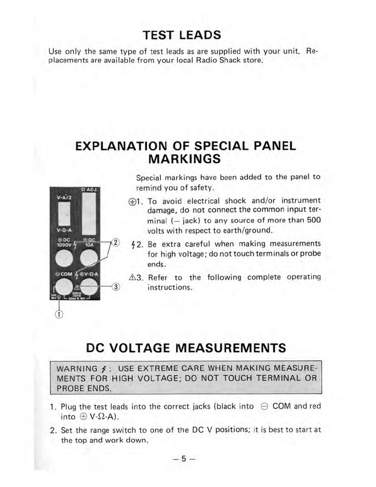
Always observe correct test lead polarity when making DC measurements:
black into the ©COM and red into the ©V-&-A (or ©DC 1000V or ©
DC 10A) jacks.
The maximum input limit for voltage and current measurement between
®V-fi-A and ©COM is 1000V AC, 250V DC and 500mA DC.
Exercise extreme caution when measuring voltages of 150 and above.
When not in use, always leave the range switch in the OFF position.
Use the range doubler switch as follows:
For resistance readings, always use the V-fi-A position.
When using the V-A/2 position for all other functions, divide the range
switch setting by 2and read on an appropriate scale. For example: range
set to 250 AC Vand V-A/2 -the range is 125 volts (250 divided by 2)
and you should read the red scale, following the 0to 125 markings. An-
other example: lead in ©COM and ©DC 10A with range set to 10A and
V-A/2 -the range is 5amperes (10 divided by 2) and you should read the
black scale, following the 0to 50 markings.
-4-

TEST LEADS
Use only the same type of test leads as are supplied with your unit. Re-
placements are available from your local Radio Shack store.
EXPLANATION OF SPECIAL PANEL
MARKINGS
Special markings have been added to the panel to
remind you of safety.
To avoid electrical shock and/or instrument
damage, do not connect the common input ter-
minal (— jack) to any source of more than 500
volts with respect to earth/ground.
Be extra careful when making measurements
for high voltage; do not touch terminals or probe
ends.
*2.
A3. Refer to the following complete operating
instructions.
DC VOLTAGE MEASUREMENTS
fARN ING i:USE EXTREME CARE WHEN MAKING MEASURE-
iNTS FOR HIGH VOLTAGE; DO NOT TOUCH TERMINAL OR
1. Plug the test leads into the correct jacks (black into 0COM and red
into 0V-ft-A).
2. Set the range switch to one of the DC Vpositions; it is best to start at
the top and work down.
-5-

If you're uncertain about the level of voltage, start with 1000 volt range
as stated on step 5. Then set the range doubler switch to V-A/2 posi-
tion (now 500V range), etc.
3. Connect the test probe tips to the circuit under test; be sure to observe
correct polarity. Set the range and the range doubler switches as re-
quired to obtain ameter reading in the upper 112 or 1/3rd of the scale.
4. Read the voltage on the black DC scales. If the range doubler switch is
in the V-A/2 position, be sure to divide the range switch setting by 2
and read on the appropriate scale.
5. For voltages between 250 and 1000, set the range switch to 250 &1000
and plug the red test lead into the 1000 Volt DC only jack. For volt-
ages between 250 and 500, set the range doubler switch to V-A/2. (The
range is then 500 volts.) For voltages between 500 and 1000, set the
range doubler switch to V-f2-A. (The itange is then 1000 volts.)
Note: The 1000 Volt DC only jack is for use only with DC voltages of
250 to 1000.
USE EXTREME CARE WHEN "USING THESE HIGH-VOLTAGE
RANGES.
AC VOLTAGE MEASUREMENTS
1. Plug the test leads into the correct jacks (black into ©COM and red
into ©V-ft-A).
2. Set the range switch to one of the ACV positions; it is best to start at
the top and work down.
3. Connect the test probe tips to the circuit under test. Set the range and
the range doubler switches as required to obtain ameter reading in the
upper 1/2 or 1/3rd of the scale.
4. Read the voltage on the red AC scale, following black numbers printed
below the red scale. If the range doubler switch is in the V-A/2 posi-
tion, be sure to divide the range switch setting by 2and read the appro-
priate scale.
-6-

RESISTANCE MEASUREMENTS
BEFORE TAKING ANY RESISTANCE MEASUREMENTS, DISCON-
NECT POWER TO THE UNIT UNDER TEST AND DISCHARGE THE
CAPACITORS. It is best to remove batteries and unplug line cords.
1.Plug the test leads into the QCOM and ©V-S2-A jacks.
2. Leave the range doubler switch in the V-I2-A position. Set the range
switch to one of the £2 positions; touch the test probe tips together and
adjust the OHM ADJ. control to bring the pointer to "0" on the top
(green) OHMS scale.
3. Now, connect the probe tips across the circuit or part under test.
4. Read the resistance on the green OHMS scale; use the proper multiplier
to obtain the correct value (R "times" 1, 10, 100, 1000, or 10,000
depending on the position of the range switch).
Notes: When you are unable to adjust the pointer to "0" on the OHMS
scale in the Rx1, Rx10, Rx100 or Rx1K positions, the penlight bat-
tery must be replaced. When you are unable to adjust the pointer to "0"
on the OHMS scale when in the Rx10K position, replace the 9-volt bat-
tery. When measuring resistance, it is best to disconnect one side of the
part under test (so the remainder of the circuit will not interfere with the
readings).
THE RANGE DOUBLER SWITCH MUST BE LEFT IN THE V-I2-A POSI-
TION FOR ALL RESISTANCE MEASUREMENTS.
-7-

DC CURRENT MEASUREMENTS
WARNING: DO NOT APPLY VOLTAGE TO MEASURING TERMI-
NAL WHILE RANGE SWITCH IS IN CURRENT POSITION.
1.Plug the test leads into the correct jacks (black into 0COM and red
into ©V-n-A).
2. Set the range switch to the 500m DC Aposition (500 milliamp). Or, if
the current will be greater than 500mA, use the ©DC 10A jack (in-
stead of the ©V-S2-A) and set the range to 10A. Always start at the
top and work down.
3. Open up the circuit in which you want to measure current and connect
the black lead to the negative side and the red lead to the positive side
of the circuit.
4. Apply power to the circuit under test.
Set the range and the range doubler switches as required to obtain a
meter reading in the upper 1/2 or 1/3rd of the scale.
5. Read the current on the black DC scales. If the range doubler switch is
in the V-A/2 position, be sure to divide the range switch setting by 2
and read the appropriate scale.
Notes: Do not attempt to read AC current. For currents above 500
milliamps, use the 10A range switch setting and the ©DC 10A jack (in-
stead of the ©V-H-A jack). Use the appropriate setting of the range dou-
bler switch.
DECIBEL MEASUREMENTS
1.Plug the test leads into the correct jacks (black into ©COM and red
into ©V-ft-A).
2. Set the range and the range doubler switches as required to obtain a
meter reading in the upper 1/2 of the scale.
3. Read dB on the dB scale, adding the appropriate number of dB to the
dB scale reading as noted on the chart at the lower right on the meter
face.
Note: For absolute dB measurements, circuit impedance must be 600
ohms. 0dB =1milliwatt dissipated in a 600 ohm impedance (equivalent
to 0.775 volts across 600 ohms).
-8-

REPLACEMENT OF BATTERY/FUSE
WARNING: TO AVOID ELECTRIC SHOCK, DISCONNECT MEAS-
URING TERMINALS BEFORE REMOVING BATTERY OR FUSE.
ONLY WITH SAME TYPE BATTERY OR FUSE. OPEN
OR FUSE. DO NOT
USE.
EE, RE-
Note: The fuse will blow when voltage is applied in resistance or current
mode. In this case, there will be no meter movement. (Replace the fuse.)
To install or replace the battery or fuse:
1. Disconnect the test leads.
2. Open the cabinet by loosening the three screws.
3. Replace the battery if necessary.
4. If the fuse has blown, remove it.
5. Insert anew fuse, using only one of the same type/rating (0.75A, 250V).
6. Close the cabinet and replace the screws.
GOOD METER MEASUREMENT PRACTICES
There are some good general rules that apply to the use of electrical meters.
Some are common-sense; others are important safety precautions.
1. CAUTION: There is always the possibility of dangerous voltages being
present in any piece of electrical/electronic equipment. Always use
extreme caution when making measurements —high voltage may appear
at unexpected points inasuspected defective circuit.
2. When making measurements, never stand on awet or damp floor. Do
not work on or even near any grounded metal object —for example, a
metal work table, metal water or gas pipes, metal electrical conduit.
Accidental contact between the grounded metal object and the circuit
under test can be lethal.
-9-

3. Always use only well insulated test leads. Never use test leads without
insulated test prods. Never allow your fingers to touch the bare metal
part of the test probes (or circuit points).
4. Never use test leads with frayed or broken insulation; voltages will
appear at all exposed contact points on the leads.
5. Never attempt to measure voltages or currents above the specified max-
imum the meter is designed for; refer to specifications section.
6. For safety's sake, disconnect leads as soon as you've completed measure-
ments.
7. Always turn off power to the unit before connecting test leads. This is
especially true when working on circuits with 100 or more volts.
8. Get into the habit of keeping one hand in your pocket when trouble-
shooting any equipment containing high voltage circuitry.
9. You should remember that even asmall shock can be dangerous, be-
cause your body's reaction to aminor shock can cause you to bump or
fall against ahigher voltage contact.
10. Discharge filter capacitors before connecting test leads; such capacitors
can retain hazardous charges in units with high voltage circuits.
11. When making voltage and current measurements always start with the
highest range available.
12. Never attempt to measure avoltage when the function is set to resist-
ance or current. (It may burn out the meter movement or other cir-
cuitry.) Never attempt to measure current with the meter set for resist-
ance.
13. Never attempt to measure AC voltages or current with the meter set to
aDC mode. (Meter circuitry can be damaged.)
14. Do not attempt to measure RF voltages with the Meter. (It can be
damaged, or at best the readings will be meaningless.)
15. Do not expose your meter to moisture; avoid high humidity and excessive
dust and dirt.
16. Avoid vibration or mechanical shock; the Meter might be damaged or
its accuracy affected.
17. Avoid using meters in locations with high magnetic fields. (Inaccurate
measurements can result.)

18. Remember that voltage and resistance measurements are made with the
Meter connected in parallel. Current measurements are made with the
Meter connected in series.
PARALLEL METER CONNECTION
For Voltage and Resistance Measurements
To
remainder
of
unit under
test
SERIES METER CONNECTION
For Current Measurements
1
To Resistor
remainder or
of other
unit under circuit
test element
Break
Circuit
Multitester
o
11 -

SCHEMATIC DIAGRAM
NOTES: (1) ALL RESISTANCE VALUES ARE INDICATED IN "OHM" (K-10* OHM, M-10* OHM)
(2) ALL CAPACITANCE VALUES ARE INDICATED IN "«F" (P=10'*jiF)
CAUTION :THE PARTS WITH EXCLAMATION MARK AINDICATE SAFETY CRITICAL COMPONENTS
FOR CONTINUED SAFETY.
Schematic subject to change without notice. For most accurate Schematic (and
parts) contact Radio Shack, National Parts Dept.. Barrie. Ontario, L4M 4W5
RADIO SHACK DIVISION, TANDY ELECTRONICS LIMITED
CANADA: BARRIE, ONTARIO L4M 4W5
U.S.A.: FORT WORTH, TEXAS 76102
TANDY CORPORATION
AUSTRAL AUK BELGIUM
91 KURRAJONG AVENUE FJILSTON ROAD WEDNESFJURY PARC INDUSTRIEL DE NANINNE
MOUNT ORUITT. NSW 2770 WEST MIDLANDS WS10 7JN 5140 NANINNE
5A4 Printed in Korea
Table of contents
Other Micronta Test Equipment manuals