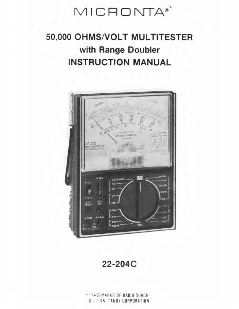
Micronta 22-214A User manual

Cat.
No.
22-214A
43-RANGE
MULTITESTER
|
PLEASE
READ
BEFORE
USING
THIS
EQUIPMENT
MICRONTA®

FEATURES
|
This
high-sensitivity
MICRONTA
Multitester
is
designed
to
measure
AC
and
DC
voltages,
DC
current
and
resistance
with
accuracy
and
ease.
The
range
doubler
switch
(V-A/2
-
V-0-A)
effectively
doubles
the
number
of
AC
and
DC
scales
available.
This
means
you
can
obtain
meter
readings
in
the
upper
half
of
the
scale,
resulting
in
more
accuracy.
The
lowest
DC
ranges
-
125mV
and
25uA
-
are
great
for
solid-state
circuit
work.
The
sensitive
18uA
meter
movement
with
4-1/2”
face
and
mirrored
scale
makes
accurate
reading
a
simple
matter.
The
meter
scales
are
in
three
colors
for
rapid
identification
The
meter
circuit
incorporates
diodes
and
a
fuse
to
protect
the
delicate
meter
movement
and
other
internal
parts
in
case
of
short-
term
inadvertent
overload
or
improper
function
selection.
A
special
audible
continuity
function
has
been
incorporated.
When
using
this
function,
a
built-in
buzzer
will
sound
when
the
circuit
continuity
is
approximately
300
ohms
or
less
The
large,
single-knob
range/function
control
is
easy
to
use
and
read.
An
off
position
is
provided
to
ensure
meter
protection
during
transit
by
shunting
the
meter
movement.
©
1990
Tandy
Corporation.
All
Rights
Reserved.
Micronta
and
Radio
Shack
are
registered
trademarks
of
Tandy
Corporation.
Features
The
handle
can
be
flipped
around
to
the
CONTENTS
h
to-read
aie,
support
the
tester
at
an
easy-to-reai
FEATURES
-occeccececceccccceccece.
2
}
SPECIFICATIONS
a.
asc
canst
5%
stcistnutaty
.
4
These
features
combined
with
rugged
CONTROLS
AND
FUNCTIONS
. -
6
design
and
quality
parts
ensure
you
of
many
SETTING
UP
YOUR
METER
....-..+.--
9
MAKING
MEASUREMENTS
...........
13
years
of
accurate
measurements.
Caution:
Permanent
damage
can
occur
to
your
Multitester
from
exceeding
the
specified
limits
or
attempting
to
make
measurements
with
the
range
switch
in
wrong
position.
REPLACEMENT
OF
BATTERY/FUSE
...
28
GOOD
METER
MEASUREMENT
PRACTICES
34
a
quedigzacgea
DURES.
NOT
FOR
COMMERCIAL
OR
INDUSTRIAL
USE.
WARNING
:
USE
EXTREME
CAUTION
IN
THE
USE
OF
THIS
DEVICE.
IMPROPER
USE
OF
THIS
DEVICE
CAN
RESULT
IN
INJURY
OR
DEATH
FOLLOW
ALL
SAFEGUARDS
SUGGESTED
IN
THE
OWNER'S
MANUAL
IN
ADDITION
TO
NORMAL
SAFETY
PRECAUTIONS
IN
DEALING
WITH
ELECTRICAL
CIRCUITS.
DO
NOT
USE
THIS
DEVICE
IF
YOU
ARE
UNFAMILIAR
WITH
ELECTRICAL
CIRCUITS
AND
TESTING
PROCE-

Batteries
18yA
full
scale
Requires
one
1.5V
AA
penlight
battery
and
one
9-volt
rectangular
type
battery
SPECIFICATIONS
i
Ranges
:
43
Decibel
—20
to
+62
dB
in
8
ranges
DC
Voltage
:
0-125-250mv
-
1.25-2,5-5-10-25-
‘Accuracy
50-125-250-500-
F
DC
Voltage
:
+3%
of
full
scale
1000
volts
2
value
except
as
AC
Voltage
0-5-10-25-50-125-
Fioted
bei
250-500-1000
volts
+4%
of
full
scale
value
for
0.125
to
DC
Current
0-25-50pA-2.5-5-
2.5
volts,
500
and
25-50-250-500mA-
1000
volts
5-10
amperes
AC
Voltage
+4%
of
full
scale
Resistance
0-2K-20K-2
Meg-20
value
Meg
ohms
(center
scale
10)
DC
Current
:
+3%
of
full
scale
value
Buzzer
Continuity
|
Approx.
less
than
300
ohms
Resistance
+3%
of
full
scale
length
4
Specifications
Sensitivity
DC:
50,000
Test
Leads
Banana
plug
style
ohms/
volt
(V-A/2)
(Cat.
No,
278-704)
or
25,000
ohms/
volt
(V-0-A)
Fuse
0.75A
250V
AC:
10,000
ohms/volt
(V-A/2)
Dimensions
or
5,000
ohms/volt
(HxWxD)
6-11/16"
x
4-7/8"
x
(V-0Q-A)
2-3/8"
(170x124x60
mm)
Meter
Movement:
4-1/2”,
3-color,
mirrored
scale,
Weight
11b
302
(550g)

CONTROLS
AND
FUNCTIONS
L
1.
Scale
For
ACV,
DCV,
OHMS,
DCA
and
dB
readings.
Look
at
the
scale
from
the
point
where
the
pointer
and
its
reflection
in
the
mirror
come
together.
2.
Zero
Adjust
Screw
————
__
Use
to
rest
the
pointer exactly
over
“0”
at
the
left
side
of
the
AC/DC
scale.
3.
OHMS
ADJ.
Control
Use
to
bring
the
pointer
to
O"
on
the
OHMS
scale
when
measuring
resistance.
4.
©
DC
1000V
Jack
Use
only
when
measuring
DC
voltage
of
250
to
1000V.
5.
®
DC
10A
Jack
————
__
Use
only
when
measuring
DC
current
of
above
500
mA.
6.
©
V-2N-A
Jack
Connect
red
lead
(+)
for
all
measurements
except
DC
voltage
measurement
above
250V
and
DC
current
measurement
above
500mA,
7.
©
COM
Jack
Connect
black
(—)
lead
for
all
measurements.
8.
Range
Switch
Turn
the
knob
so
that
the
white
mark
on
the
rim
points
the
position
that
results
in
a
meter
reading
in
the
upper
1/2
or
1/3rd
of
the
scale.
Set
to
OFF
when
the
meter
is
not
in
use.
9.
Range
Doubler
Switch
—
__
Use
the
V-A/2
position
to
divide
the
range
switch
setting
by
two.
For
resistance
measurements,
use
only
the
V-0Q-A
position,
See
‘Using
Range
Doubler
Switch.”
6
a
==
Controls
&
Functions
iis
[erat
nine
10.
Handle
Flip
around
to
the
back
to
support
the
meter
at
an
easy-to-
read
angle.

Controls
&
Functions
Explanation
of
Special
Panel
Markings
a
F
500V,
MAX
1000V
AC
[b]
[c]
ie
fe]
A
[f]
[9]
50K
-25kKQ/V
DC
TOK-5KO/V
AC
048
=1
mw
600
OHMS
Special
markings
have
been
added
to
the
panel
to
remind
you
of
safety.
a.
Add
the
appropriate
number
in
this
chart
to
the
dB
scale
reading.
See
“Decibel
Measurements.”
b.
Be
extra
careful
when
making
measurements
for
high
voltage;
do
not
touch
terminals
or
probe
ends.
c.
To
avoid
electrical
shock
and/or
instrument
damage,
do
not
connect
the
common
input
terminal
(-jack)
to
any
source
of
more
than
500
volts
with
respect
to
earth/ground.
d.
The
maximum
voltage
or
current
that
can
be
measured
between
these
terminals
is
1O0OV
AC,
250V
DC
and
500mA
OC.
e.
Refer
to
the
following
complete
operating
instructions.
f.
The
inner
resistance
of
this
tester
is
50
kohm
(DC)
or
10
kohm
(AC)
per
volt
with
the
Range
Doubler
Switch
in
the
V-
A/2
position;
25
kohm
(DC)
or
5
kohm
(AC)
per
volt
with
the
Range
Doubler
Switch
in
the
V-2Q-A
position.
g.
0
dB
means
that
1
milliwatt
is
dissipated
in
a
600
ohm
impedance.
‘
SETTING
UP
YOUR
Battery
Installation
METE
You
will
need
to
install
one
9-volt
battery
for
the
20
Megohm
(R
X
10K)
range
and
continuity
range,
and
one
AA
1.5V
penlight
battery
for
other
resistance
ranges.
We
recommend
our
23-583/553
for
9V,
23-582/552
for
AA.
Be
sure
that
the
test
leads
are
disconnected.
Open
the
cabinet
by
removing
the
3
screws
from
the
back
and
install
the
batteries
in
the
correct
compartments.
Observe
proper
polarity.
Close
the
cabinet
and
tighten
the
screws.
Remember:
Never
leave
weak
or
dead
batteries
in
your
unit.
Even
“leak-proof”
ones
may
leak
damaging
chemicals.
Also,
if
you
are
not
going
to
use
your
unit
for
a
week
or
more,
remove
the
batteries.

=
Setting
up
Your
Meter
Zero
Adjustment
MICRONTA
If
the
pointer
does
not
normally
rest
exactly
over
“O”
at
the
left
side
of
the
scale,
adjust
the
plastic
screw
in
the
lowest
center
of
the
meter
face
to
bring
the
pointer
to
“O”
Meter
Reading
the
meter
scale.
<7
Pointer
oes
8
ae
For
most
accurate
readings,
keep
the
meter
lying
flat
on
a
non-metallic
surface.
Also,
use
a
range
and
range
doubler
switch
setting
that
results
in
a
reading
in
the
upper
1/3rd
of
To
read
the
scale,
look
at
it
from
the
point
where
the
pointer
and
its
reflection
in
the
mirror
come
together;
otherwise,
the
parallax
will
cause
an
error
in
the
reading.
10
Using
Test
Leads
Setting
up
Your
Meter
Use
only
the
same
type
of
test
leads
as
are
supplied
with
your
unit.
These
test
leads
are
rated
for
1200
volts;
replacements
are
available
from
your
local
Radio
Shack
store.
(Cat.
No.
278-704)
CAUTION:
Although
these
test
leads
(Cat.No.278-704)
are
rated
for
1200V,
the
maximum
rating
of
this
meter
is
1000V.
You
should
not
attempt
to
measure
any
voltage
greater
than
1000V.
Always
observe
correct
test
lead
polarity
when
making
DC
measurements:
The
black
lead
should
always
be
connected
to
the
©
COM
jack.
Connect
the
red
lead
to@
(@
V-2-A)
for
making
DC
measurements
up
to
250V,
DC
current
up
to
500mA,
all
AC
voltage
and
resistance
measurements;
connect
it
to
®
(GDC
1000V)
when
measuring
DC
voltage
from
250V
to
1000V;
and
connect
it
to
©
(@
DC
10A)
when
measuring
DC
current
from
500mA
to
10A.
NEVER
ALLOW
YOUR
FINGERS
TO
TOUCH
THE
BARE
METAL
PART
OF
THE
TEST
PROBES
(OR
CIRCUIT
POINTS).
For
safety’s
sake,
disconnect
the
leads
from
the
circuit
under
test
as
soon
as
you
have
completed
measurements.
i
Black
Lead
Red
Lead
f
I
Cine
Gar
Ne
|
pases!
®,
11

Setting
up
Your
Meter
Using
Range
Doubler
Switch
For
resistance
measurements,
always
use
the
V-0-A
position.
When
using
the
V-A/2
position
for
all
other
functions,
divide
the
range
switch
setting
by
2
and
read
on
an
appropriate
scale.
Examples:
1.
Range
switch
is
set
to
250
V
AC
and
range
doubler
switch
is
set
to
V-A/2.
—
The
range
is
125
volts
(250
divided
by
2)
and
you
should
read
the
red
scale,
following
the
O
to
125
markings.
2.
Range
switch
is
set
to
10A
and
range
doubler
switch
is
set
to
V-A/2.
(Black
lead
is
plugged
in
-
COM
and
red
lead
in
+
DC
10A.)
—
The
range
is
5
amperes
(10
divided
by
2)
and
you
should
read
the
black
scale,
following
the
O
to
50
markings.
12
MAKING
DC
Voltage
Measurements
MEASUREMENTS
WARNING:
USE
EXTREME
CARE
WHEN
MAKING
HIGH
VOLTAGE
MEASUREMENTS;
DO
NOT
TOUCH
TERMINAL
OR
PROBE
ENDS.
1.
Plug
the
black
lead
into
©
COM
and
the
red
lead
into
@
V-0-A
jack.
2.
Set
the
range
switch
to
one
of
the
DC
V
positions;
it
is
best
to
start
at
the
highest
range
and
work
down.
If
you
are
uncertain
about
the
level
of
voltage,
start
with
the
1000
volt
range.
See
step
6
on
next
page.
3.
Connect
the
test
probe
tips
to
the
circuit
under
test;
be
sure
to
observe
correct
polarity.
S2FE/9.0.
\
eS
|
Battery

Making
Measurements
V-A/2
V-0-A
4.
Set
the
range
and
the
range
doubler
switches
as
required
to
obtain
a
meter
reading
in
the
upper
1/2
or
1/3rd
of
the
scale.
5.
Read
the
voltage
on
the
black
DC
scales.
If
the
range
doubler
switch
is
in
the
V-A/2
position,
be
sure
to
divide
the
range
switch
setting
by
2
and
read
on
the
appropriate
scale.
6.
For
voltages
between
250
and
1000,
set
the
range
switch
to
250
&
1000
and
plug
the
red
lead
into
@
DC
1000V
jack.
For
voltages
between
250
and
500,
set
the
range
doubler
switch
to
V-A/2.
(The
range
is
then
500
volts.)
For
voltages
between
500
and
1000,
set
the
range
doubler
switch
to
V-0-A.
(The
range
is
then
1000
volts.)
14
Making
Measurements
Note:
The
@
DC
1000V
jack
is
for
use
only
with
DC
Netitral
dr
voltages
of
250
to
1000V.
USE
EXTREME
CARE
WHEN
Ground
wire
‘Hot”
wire
USING
THESE
HIGH-VOLTAGE
RANGES.
Test
unit
Hints:
When
you
use
the
tester
to
probe
for
a
voltage
in
a
[woo
%
high
voltage
circuit,
we
recommend
that
you
do
not
try
to
oe
position
both
of
the
probes
at
once.
Instead,
you
should
clamp
one
of
the
leads
to
the
neutral
or
ground
lead
of
the
circuit
(usually
a
bare,
green
or
white
lead
in
AC
wiring
circuit)
using
our
Insulated
Slip-On
Alligator
Clips
(Cat.
No.
270-354),
and
then
probe
for
voltages
with
the
other
probe.
This
helps
to
prevent
you
from
accidentally
touching
a
“hot’’
wire,
since
you
need
only
concentrate
on
one
test
probe.
Never
clamp
on
to
a
“hot”
wire,
(usually
red,
black
or
blue
in
AC
wiring
circuit),
since
if
you
did
so
and
then
touched
the
other
probe
connected
to
the
meter,
you
could
receive
an
electric
shock.
Pain
Alligator
Clip
(270-354)
Black
Lead
Red
Lead
]
15

Making
Measurements
AC
Voltage
Measurements
OR
PROBE
ENDS.
V-0-A.
WARNING:
USE
EXTREME
CARE
WHEN
MAKING
HIGH
VOLTAGE
MEASUREMENTS;
DO
NOT
TOUCH
TERMINAL
1.
Plug
the
black
lead
into
Q
COM
and
the
red
lead
into
@
2.
Set the
range
switch
to
one
of
the
ACV
positions.
It
is
best
to
start
at
the
highest
range
and
work
down.
3.
Connect
the
test
probe
tips
to
the
circuit
under
test.
6
r
Making
Measurements
4.
Set the
range
and
the
range
doubler
switches
as
required
to
obtain
a
meter
reading
in
the
upper
1/2
or
1/3rd
of
the
V-A2
V-0-8
scale.
5.
Read
the
voltage
on
the
red
AC
scale,
following
black
numbers
printed
below
the
red
scale.
If
the
range
doubler
switch
is
in
the
V-A/2
position,
be
sure
to
divide
the
range
switch
setting
by
2
and
read
the
appropriate
scale.
*
Above
scale
reads
180
volts
if
the
range
is
set
to
250V
with
range
doubler
switch
set
at
V-0-A.
L
17

Making
Measurements
AC
Voltage
Riding
on
a
DC
Source
Bias
Measurements
oil
Set
the
range
SW
to
ACV
aha
"0,
[ox
pret
Note:
When
measuring
an
AC
voltage
superimposed
on
a
DC
voltage
source
bias,
ordinary
measurements
cannot
be
made.
Under
such
conditions,
if
you
know
the
approximate
voltage
of
the
device
to
be
measured
and
the
voltage
is
UNDER
30V
DC/AC,
you
can
measure
the
voltage
by
connecting
a
0.14F/100V
polyester
film
capacitor
in
series
with
the
positive
terminal
of
the
voltage
source
and
the
(+)
test
lead.
The
range
switch
is
set
to
ACV.
WARNING:
NEVER
ATTEMPT
TO
MEASURE
OVER
30V
AC
ON
DC
SOURCE
BIAS.
Red
Lead
Black
Lead
[se
0.1.F/100V
Polyester
film
Capacitor
18
a
Measuring
3-Phase
AC
Voltages
Making
Measurements
which
is
1000VAC.
of
3
(approx.
1.732)
circuit.
This
tester
is
designed
primarily
to
measure
household
AC
voltages.
When
measuring
3-phase
circuits
line-to-line,
the
value
of
the
voltage
will
actually
be
higher
than
the
rated
line-to-ground
3-phase
voltage.
It
is
important
that
you
do
not
exceed
the
maximum
RMS
AC
rating
of
this
meter,
=
=
To
determine
the
RMS
voltage
line-to-line
on
a
3-phase
line,
multiply
the
rated
line-to-ground
voltage
by
the
square
root
For
example,
on
a
““600-volt
3-phase
line”
(i.e.
GOOV
line-to-
ground),
the
total
available
voltage
line-to-line
is
600
=
1.732,
or
approximately
1039 VAC.
This
exceeds
the
rating
of
this
tester.
Severe
damage
as
well
as
a
dangerous
shock
hazard
could
result
if
the
meter
were
connected
to
this
Watch
for
3-phase
circuits
line-to-line.
The
voltage
will
be
higher
Remember
1000VAC
is
maximum
19

Making
Measurements
Resistance
Measurements
V-0-A
jack.
WARNING:
DO
NOT
APPLY
VOLTAGE
TO
TEST
LEADS
WHEN
THE
RANGE
SWITCH
IS
IN
OHMS
POSITION.
BEFORE
TAKING
ANY
RESISTANCE
MEASUREMENTS,
DISCONNECT
POWER
TO
THE
UNIT
UNDER
TEST
AND
DISCHARGE
THE
CAPACITORS.
It
is
best
to
remove
any
batteries
(from
unit
under
test)
and
unplug
line
cords.
1.
Plug
the
black
lead
into
©
COM
and
the
red
lead
into
@
2.
Leave
the
range
doubler
switch
in
the
V-0-A
position.
THE
RANGE
DOUBLER
SWITCH
MUST
BE
LEFT
IN
THE
V-
-A
POSITION
FOR
ALL
RESISTANCE
MEASUREMENTS.
3.
Set
the
range
switch
to
one
of
the
OHMS
positions.
20
Making
Measurements
4.
Touch
the
test
probe
tips
together
and
adjust
the
OHMS
ADJ.
control
to
bring
the
pointer
to
“O"
on
the
top
(green)
OHMS
scale.
If
you
cannot
adjust
the
pointer
to
“0”
on
the
OHMS
scale
when
you
short
the
test
leads
together,
replace
the
battery
with
a
new
one.
When
you
are
unable
to
adjust
the
pointer
to
0"
on
the
OHMS
scale
in
the
R
X
1,
R
X
10,
or
R
X
1K
positions,
the
1.5V
penlight
battery
must
be
replaced.
When
you
are
unable
to
adjust
the
pointer
to
“0”
on the
OHMS
scale
when
in
the
R
X
10K
position,
replace
the
9-
volt
battery.
See
“REPLACEMENT
OF
BATTERY/FUSE.”
21

Making
Measurements
22
test.
the
range
switch).
5.
Connect
the
probe
tips
across
the
circuit
or
part
under
When
measuring
resistance,
it
is
best
to
disconnect
one
side
of
the
component
under
test
so
the
remainder
of
the
circuit
will
not
interfere
with
the
readings.
6.
Read
the
resistance
on
the
green
OHMS
scale.
Use
the
proper
multiplier
to
obtain
the
correct
value
(R
“times’’
1,
10,
1000,
or
10,000
depending
on
the
position
of
Note
for
Testing
Semiconductor
Junctions:
When
attempting
to
identify
cathode
and
anode
ends
or
the
type
of
transistor
(PNP
or
NPN),
the
actual
polarity
of
the
tester’s
voltage
is
opposite
of
the
lead
colors.
The
red
lead
is
the
negative
source.
The
black
lead
is
positive
Continuity
Check
«
Making
Measurements
1.
Plug
the
black
lead
into
©
COM
and
the
red
lead
into
@
V-0-A.
2.
Set
the
range
switch
to
the
CONT
position
on
the
OHMS
range.
3.
Leave
the
range
doubler
switch
in
the
V-(0-A
position.
4.
Connect
the
test
leads
to
the
unit
under
test.
5.
If
the
resistance
is
O
to
300
ohms
(approx.),
the
built-in
buzzer
sounds.
The
level
of
the
sound
reduces
as
the
resistance
increases.
Note:
If
the
buzzer
does
not
sound
when
you
short
the
test
leads,
replace
the
9-volt
battery.
23

24
Making
Measurements
DC
Current
Measurements
POSITION.
50uA/5MA/50MA/500mA
Range
For
50uA/5mA/50mA/500mA
measurements:
Plug
the
red
lead
into@®V-(-A
and
the
black
lead
intoOQCOM.
Qe
||
eg
peg
|
b
SFT
1:0)
Black
Lead
Red
Lead
tnenh
3.
Remove
power
from
the
circuit
under
test
and
then
break
To
measure
current,
you
must
break
the
circuit
and
connect
the
leads
in
series
with
the
circuit.
WARNING:
DO
NOT
APPLY
VOLTAGE
TO
THE
TEST
LEADS
WHEN
THE
RANGE
SWITCH
IS IN
THE
CURRENT
1.
Set
the
range
switch
to
one
of
the
DCA
positions.
Always
start
at
the
highest
range
and
work
down.
2.
For
10A
measurement:
Plug
the
red
lead
into@)DC
10A
Red
Lead
and
the
black
lead
intoQCOM.
the
circuit
at
the
appropriate
point.
Making
Measurements
4.
Connect
probes
to
the
circuit
in
series.
(black
lead
to
the
negative
side
and
the red
lead
to
the
positive
side).
5.
Apply
voltage
to
the
circuit
under
test.
6.
Set
the
range
and
the
range
doubler
switches
as
required
to
obtain
a
meter
reading
in
the
upper
1/2
or
1/3rd
of
the
scale.
7,
Read
the
current
on
the
black
DC
scales.
If
the
range
doubler
switch
is
in
the
V-A/2
position,
be
sure
to
divide
the
range
switch
setting
by
2
and
read
the
appropriate
scale.
25

Making
Measurements
Decibel
Measurements
1.
Plug
the
black
lead
into
©
COM
and
red
lead
into
©
V-0-A.
2.
Set
the
range
switch
to
one
of
the
ACV
positions;
it
is
best
to
start
at
the
highest
range
and
work
down.
3.
Connect
the
test
probe
tips
to
the
circuit
under
test.
4.
Set
the
range
and
range
doubler
switches
as
required
to
—
bases
obtain
a
meter
reading
in
the
upper
1/2
or
1/3rd
of
the
dB
scale.
26
Making
Measurements
———_—
must
be
600
ohms.
5.
Read
dB
on
the
dB
scale,
adding
the
appropriate
number
of
dB
to
the
dB
scale
reading
as
noted
on
the
chart
at
the
lower
right
on
the
meter
face.
Note:
For
absolute
dB
measurements,
circuit
impedance
0
dB
=
1
milliwatt
dissipated
in
a
600
ohm
impedance
(equivalent
to
0.775
volts
across
600
ohms).
27

REPLACEMENT
OF
BATTERY/FUSE
WARNING:
TO
AVOID
ELECTRIC
SHOCK,
DISCONNECT
THE
TEST
LEADS
BEFORE
REMOVING
THE
BATTERY
OR
FUSE,
REPLACE
ONLY
WITH
THE
SAME
TYPE
BATTERY
OR
FUSE.
OPEN
THE
CABINET
ONLY
WHEN
REPLACING
THE
BATTERY
OR
FUSE.
DO
NOT
TOUCH
ANY
AREA
INSIDE
THE
CASE
OTHER
THAN
BATTERY
OR
FUSE.
CAUTION:
FOR
CONTINUED
PROTECTION
AGAINST
FIRE,
REPLACE
ONLY
WITH
0.75A,
250V
FUSE
SUCH
AS
OUR
CAT.
NO.
270-1272.
Note:
The
fuse
will
blow
when
voltage
is
applied
when
tester
is
in
OHMS
range,
or
current
range
(except
10A
range),
on
when
excess
voltage
is
applied
to
0.25
DCV/
0.125DCV
range.
When
the
fuse
blows,
there
will
be
no
deflection
of
meter.
28
To
install
or
replace
the
battery
or
fuse:
Replacement
of
Battery/Fuse
1.
Disconnect
the
test
leads.
2.
Open
the
cabinet
by
loosening
three
screws
on the
back.
3.
Replace
the
battery
if
necessary.
Install
one
9
V
battery
such
as
our
Cat.Nos.23-583/553
and
one
AA
1.5V
penlight
battery
such
as
our
Cat.
Nos.
23-582/
552.
Observe
correct
polarity.

—
Replacement
of
Battery/Fuse
4.
If
the
fuse
has
blown,
remove
it.
5.
Insert
a
new
fuse,
using
only
one
of
the
same
type/rating
(0.75A,
250V/Cat.
No.
270-1272).
One
spare
fuse
is
supplied
with
your
Multitester
inside
the
cabinet.
6.
Close
the
cabinet
and
replace
the
screws.
WARNING:
DO
NOT
OPERATE
THE
UNIT
UNTIL
THE
CABINET
IS
FULLY
CLOSED.
30
GOOD
METER
MEAS-
UREMENT
PRACTICES
Here
are
some
good
general
rules
that
apply
to
the
use
of
electrical
meters.
Some
are
common-sense;
others
are
important
safety
precautions.
1.
There
is
always
the
possibility
of
dangerous
voltages
being
present
in
any
piece
of
electrical/electronic
equipment.
Always
use
extreme
caution
when
making
measurements
-
high
voltage
may
appear
at
unexpected
points
in
a
suspected
defective
circuit.
2.
Never
attempt
to
measure
voltage
or
current
above
the
specified
maximum
the
Multitester
is
designed
for;
the
maximum
input
limit
for
voltage
and
current
measurement
between
@)
V-9-A
and
©
COM
is
1000V
AC,
250V
DC
and
500mA
DC.
3.
Exercise
extreme
caution
when
measuring
voltages
of
150V
and
above.
of
eee,
Me
*.
f2
se
Mt
OF
es
ee
cae
EXTREME
CAUTT
Gen
MAKING
MEASURE
MAY
31

Good
Meter
Measurement
Practices
4.
When
making
voltage
and
current
measurements
always
start
with
the
highest
range
available.
5.
Never
attempt
to
measure
a
voltage
when
the
function
is
set
to
resistance
or
current.
(It
may
burn
out
the
meter
movement
or
other
circuitry.)
6.
Never
attempt
to
measure
current
with
the
tester
set
for
resistance.
7.
Never
attempt
to
measure
AC
voltages
or
current
with
the
tester
set
to
a
DC
mode.
(Meter
circuitry
can
be
damaged.)
32
—
Good
Meter
Measurement
Practices
8.
Do
not
attempt
to
measure
RF
voltages
with
the
Multitester.
(It
can
be
damaged,
or,
at
best,
the
readings
will
be
meaningless.)
9.
Remember
that
voltage
and
resistance
measurements
are
made
with
the
Multitester
connected
in
parallel.
Current
measurements
are
made
with
the
Multitester
connected
in
series.
Resistor
or
other
circuit
zontact
point
To
Remainder
of
Unit
under
Test
SERIES
CONNECTION
To
Remainder
[|
Resistor
f
r
of
Unit
under
Test
Brack
Circuit
other
alement
Mulniestar
33

Good
Meter
Measurement
Practices
34
10.
When
the
Multitester
is
not
in
use,
always
leave
the
range
switch
in
the
OFF
position.
11,
When
making
measurements,
never
stand
on
a
wet
or
damp
floor.
Do
not
work
on
or
even
near
any
grounded
metal
object
—
for
example,
a
metal
work
table,
metal
water
or
gas
pipes,
metal
electrical
conduit.
Accidental
contact
between
the
grounded
metal
object
and
the
circuit
under
test
can
be
lethal.
12.
Get
into,the
habit
of
keeping
one
hand
in
your
pocket
when
troubleshooting
any
equipment
containing
high
voltage
circuitry.
13.
You
should
remember
that
even
a
small
shock
can
be
dangerous,
because
your
body's
reaction
to
a
minor
shock
can
cause
you
to
bump
or
fall
against
a
higher
voltage
contact.
Good
Meter
Measurement
Practices
14.
Do
not
expose
your
meter
to
moisture;
avoid
high
humidity
and
excessive
dust
and
dirt.
15.
Avoid
vibration
or
mechanical
shock;
the
Multitester
might
be
damaged
or
its
accuracy
affected.
16.
Avoid
using
meters
in
locations
with
high
magnetic
fields.
(Inaccurate
measurements
can
result.)
17.
Always
use
only
well
insulated
test
leads.
Never
use
test
leads
with
frayed
or
broken
insulation.
35

RADIO
SHACK
LIMITED
WARRANTY
This
product
is
warranted
against
defects
for
90
days
from
date
of
purchase
from
Radio
Shack
company-owned
stores
and
authorized
Radio
Shack
franchisees
and
dealers.
Within
this
period,
we
will
repair
it
without
charge
for
parts
and
labor.
Simply
bring
your
Radio
Shack
sales
slip
as
proof
of
purchase
date
to
any
Radio
Shack
store.
Warranty
does
not
cover
transportation
costs.
Nor
does
it
cover
a
product
subjected
to
misuse
or
accidental
damage.
EXCEPT
AS
PROVIDED
HEREIN,
RADIO
SHACK
MAKES
NO
WARRANTIES,
EXPRESS
OR
IMPLIED,
INCLUDING
WARRANTIES
OF
MERCHANTABILITY
AND
FITNESS
FOR
A
PARTICULAR
PURPOSE.
Some
states
do
not
permit
limitation
or
exclusion
of
implied
warranties;
therefore,
the
aforesaid
limitation(s)
or
exclusion(s)
may
not
apply
to
the
purchase.
This
warranty
gives
you
specific
legal
rights
and you
may
also
have
other
rights
which
vary
from
state
to
state.
We
Service
What
We
Sell
RADIO
SHACK
A
Division
of
Tandy
Corporation
Fort
Worth,
Texas
76102
Printed
in
Hong
Kong
5A3
811090770A

‘Wise
x
WOW
1104
dag
Neg
(EUO/
Joh)
“yoeYS
OIPeY
iDeVUOS
(FLEE
PUL)
SHeLIAaYDS
siEINID>e
ISD
JOY
“aiou
roo
YUM
a6UEYD
0}
IDalans
ON
eWAYIS
si
SLUYd
NO
G38INDS30
3SOHL
ANG
3S)
'ALa4¥S
HOd
TVOILIND
auY
Y
AB
OS4HWW
SLNSNOAWOO
3H1
SONIS
“NOLLNVO.
13%
Obed)
dt,
NIOZLYSIONI
ANY
SINIWA
JONVLIQVdVo
TITY
(2)
{WHO
,O1-W
WHO
(01m)
WHO.
NI
OSLVOIONI
3d
SANIWA
JONVISISZY
T1y
(I)
‘S3LON
qaysaynynyW
asuey-¢ep
<$—$—.
ae
PIZ-ZZ
!
id
wi
“eew
9
UL
RyMOSITA
~Rys
orpey
se
_|
i
OF
;
]
.
woss
coO0
wre
4
gia
size
W
Wee
:
eSDEIg
Ldbene
°
axe
o8
fle
zo
|
kevige
fou
“
‘
es
oe
|
(UH
nT
ZeS8sawo
AER
CUZ
—
(78
'A)
eLOSNtae
{|
*
o
>
w
4
(H"9'
4)
gg35z
bales
43%
A
o
=
@
tT
Sat
Bee
Se
a
©
Wh
bbe
o
war
owe
WSL
oy
_]
¥u'~a
OO]
Boor
!
}
A00nt
20
@6)
ae
mE
=
“se
THT
vor
20
@(O)
sory
ote
OW
W026)
We
TOS
ST
Te
A
We
=
Fr
ca
UMYS
WHEE
FONVASISSY
MOLLWAGIIW
GH
Ze
Cy)
NS
ze
F
|
UL¥
0
3IVWW1SIS3Y
NOLLYEBIWD
BY
Le(c)
ive
he
%
LYS)
fl
60S
Odor
(a"
Dim
lt.
6)
.
WEL
WS
NI
CaLWOION(
Safv
SATA
S2NVL(o¥avO
Tv
iz)
(AHO
OLS
AHO
0
b=)
J
HO.
NI
GRLVDIGN]
St
SBA
SONVLSISIH
Tv
th)
PEveTy
is
\
=
LAS
$240N
a
EA
i
)
1)
a
re
‘
)
Table of contents
Other Micronta Test Equipment manuals