Warning! Confirm the voltage to select switch which can be matched the circuit with the light. If it is
different from the supply power and light, it will damage the light! All the light must be connected the
earth, not all the lights have the switch to be selected.
Please connect the correct voltage!
1. Before you work
1.1 Packing list
Product name quantity
LED Panel Light 1pcs
Power -wire 1 base
1.2 Unpacki ng instruct ion s
When you get this product, please take it from carton carefully to make sure whether all the accessories are
in and damaged or not
When you find that there are any parts or wrong sign with the carton, or non-operation, please inform us and
to keep the carton and shipping bill completely.
1.3 AC Powe r
Please check the manual book before you operate the light. The rating current of the light listed which
shows the average current-consume under the normal circumstances.
All the lights must be offered shoot-through circuit, it couldn’t be connected dimmer circuit, although the
dimmer channels are completely for 1-100% switch.
Before the light’s working, please confirm the correct voltage.
1.4 Safety instructions
Please read these instructions carefully, it includes important information about the light’s installation, usage
and maintenance of this product.
Please confirm the same voltage to the light.
The light couldn’t be water-proof, it only allow to be used in door. Don’t expand the light in wet or rain day, to
avoid fire or damaged light.
Please confirm there is no flammable material around the light.
The light must be set up the ventilating place. The distance is ≥51cm around approach material. To check the
air passage is ok at any time.
The Maximum temperature is ≤40℃(104℉).
When the lights has problems, please stop to use to contact the supplier. Don’t repair it by yourself!
Don’t connect by a dimmer.
To confirm the power wire is straight and non-damaged. Don’t pull it directly.
Don’t look at the bulb when the light is working to avoid any hurt.
2. Introduction
2.1 Features
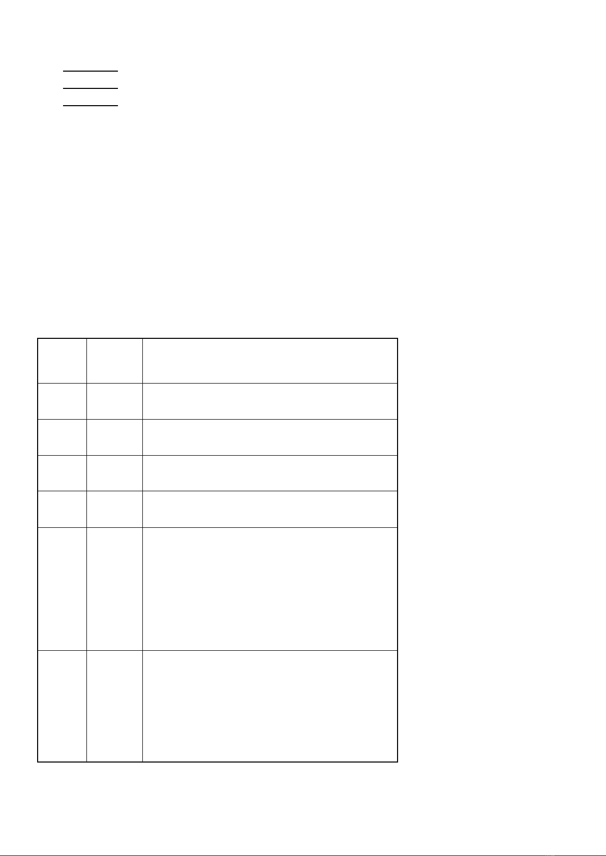
8 DMX channels.
RGB LED light source,life long is 50000-10000 hours.
Variable electronic dimmer(0-100%).
Strobe
Color:auto-running and color shade.
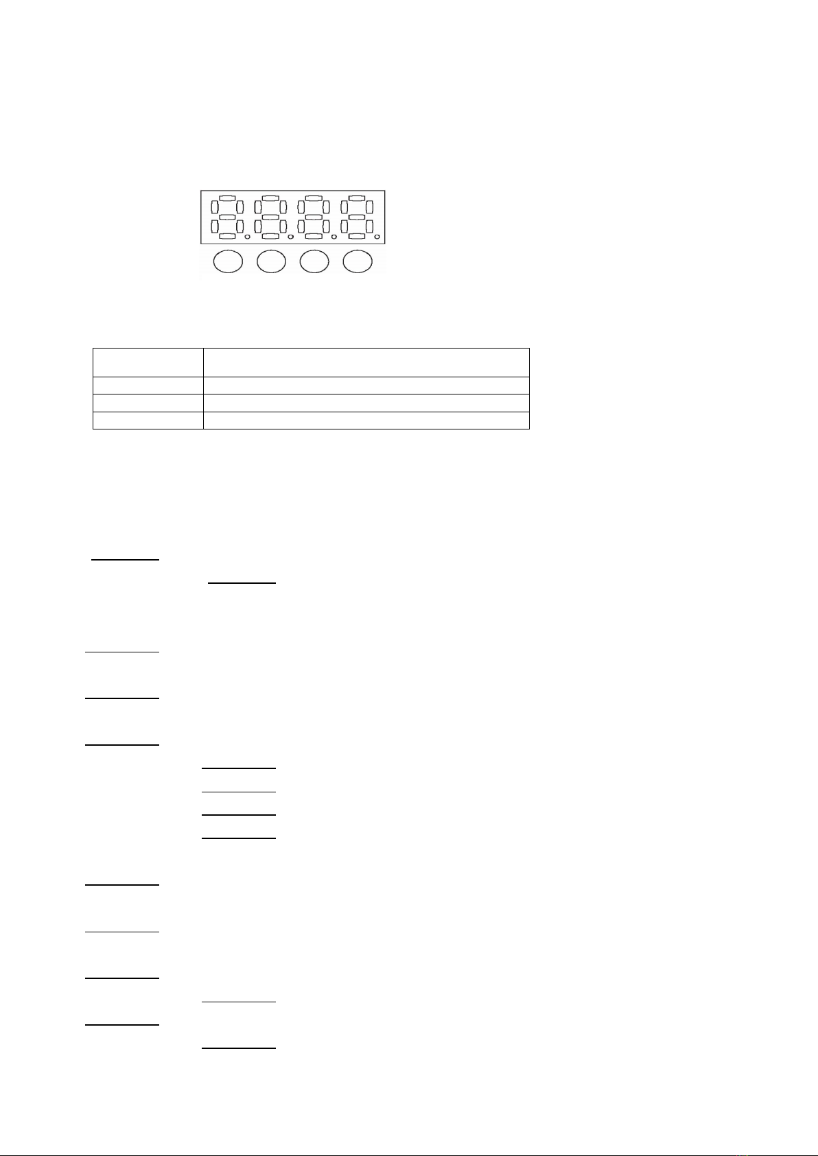
Control mode:Menu,DMX mode
Fan cooled