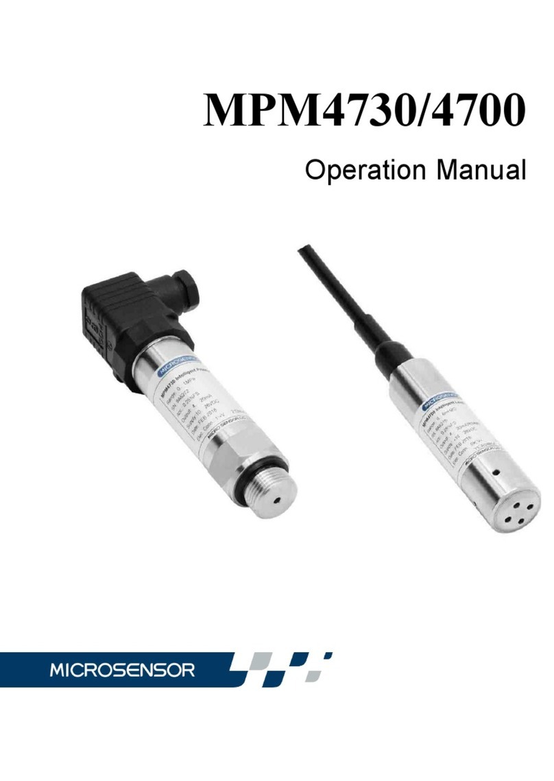
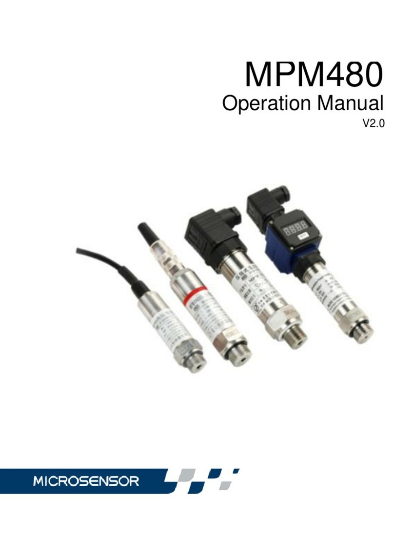
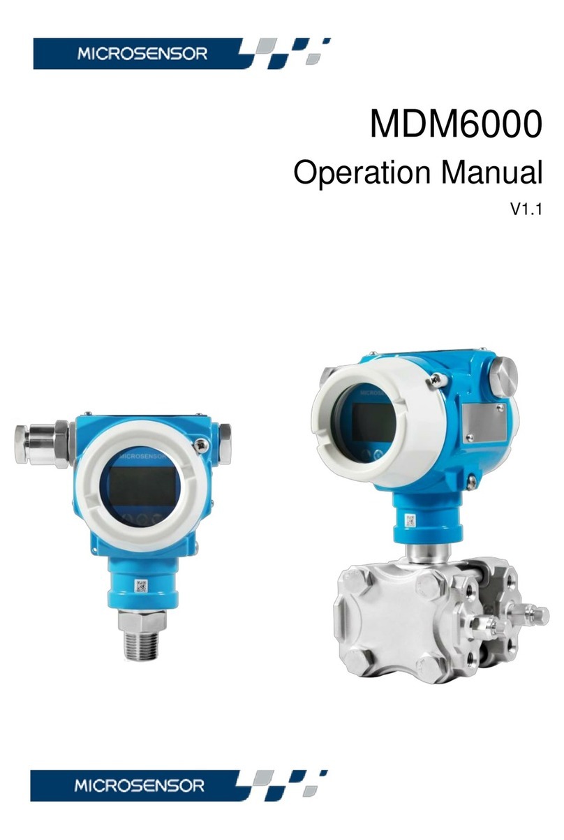
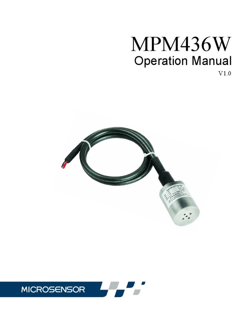
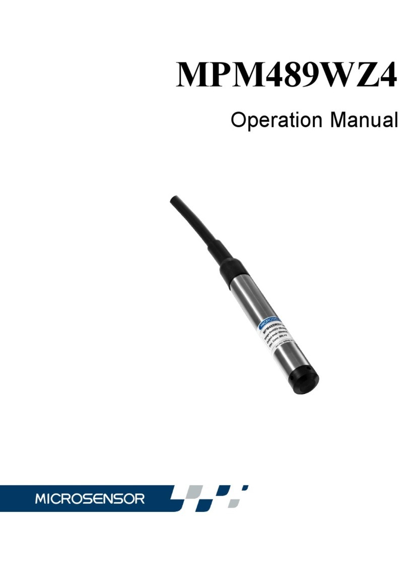
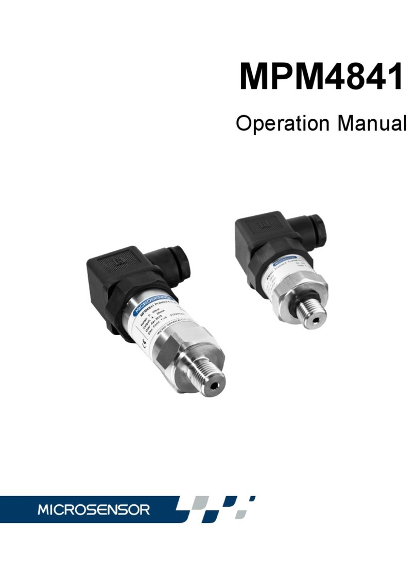
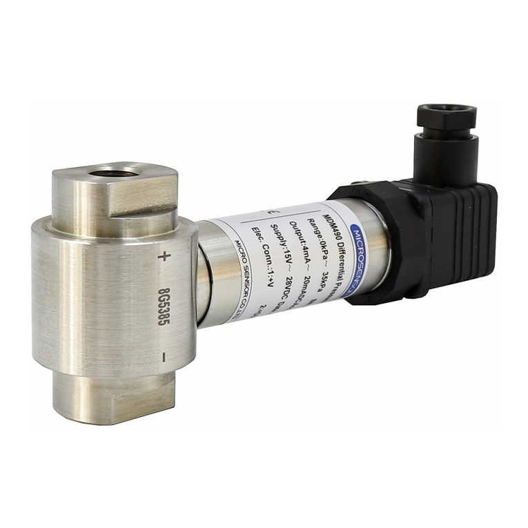
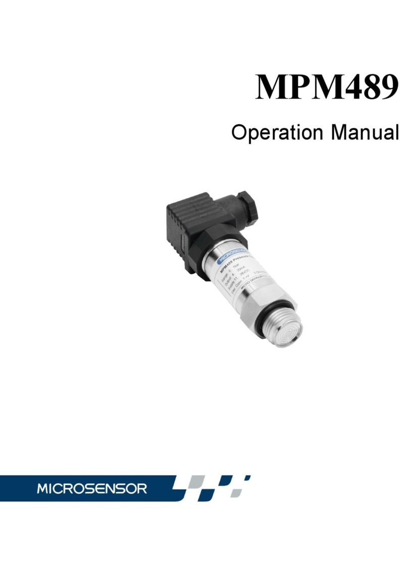
Microsensor MPM4730 User manual

V2.0
MPM4730/4700
Operation Manual

1
Thank you very much for selecting Micro Sensor’s product, please
take some time to read this operation manual very carefully before
using the product.
1 Introduction
MPM4730/4700 Intelligent Pressure Transmitter is the intelligent
pressure/level measurement instrument. Using the most advantaged
technologies and the latest achievements in scientific research in the
world, it is famous for its compact size, good stability and wide range.
The intelligent pressure transmitter is suitable for precise measurement
and control for liquid pressure/level in all various fields.
The Explosion-proof version of MPM4700 is an intrinsic safe version,
conforming the standard of GB3836.1-2010 and GB3836.4-2010.
Explode sign is ExiaⅡCT6 Ga.
Marine products conform to the requirements of CCS classification
specification for steel sea-going ships (2015) and have obtained type
approval.
Products measurement tools type approval No. 15F139-61.
2 Specification
Pressure Range: -100kPa…0kPa~10kPa…100MPa(4730)
0mH2O~3.5mH2O…200mH2O(4700)
(The least shrinking range is 1/5 basic range.)
Overpressure: 1.5 times FS or 110MPa(Min. value is valid)

2
Accuracy: ±0.075%FS (min.), ±0.1%FS (typ.), ±0.25%FS (max.)
(4730: Table pressure ≤20KPa and negative pressure and
absolute pressure ≤500KPa product accuracy ±0.5%.)
(4700: 3.5mH2O and 7mH2O liquid level transmitters are
integrated after range scaling,The accuracy is typically ±0.5%FS.);
Note:synthetic precision includes nonlinearity,hysteresis, repeatability and
temperature error.
Power Supply: 10V~28VDC(RS485 communication interface)
12V~30VDC(HARTcommunication protocol)
10V~12V(The Ann model, the security gate power supply)
Signal Output: 4mA~20mA (2-wire) ,RS485/HART(optional)
Compensated temp.:-10℃~70℃
Operation temp.:-30℃~80℃(4730B1 & B3)
-10℃~70℃(4730B2 & 4700)
-20℃~60℃(Intrinsic safe)
Storage temp.: -40℃~85℃(4730B1& B3)
-20℃~85℃(4730 B2 和4700)
Long-term Stability: ±0.2%FS (typ.)
Baud rate: 1200、2400、4800、9600 are optional
Load Resistance:(U-10V)/0.02A(Ω)(RS485, 4mA~20mA DC output)
(U-12V)/0.02A(Ω)(HART)
RS485 bus line could connect with 99 transmitter.
Insulation: 100MΩ/50V

3
Vibration: 20g (20~5000)Hz
Shock: 20g 11ms
Protection:IP65(4730 B1 & B2)、 IP63(4730 B3)
IP68(4700 Transmitter part)、 P65(Junction box part)
Cable: ф7.2mm PVC or polyurethane cable with vented tube
Weight: ~ 250g(4700 No cable)~160g(4730)
3 Outline dimension and Installation
3.1 Outline dimension (Unit:mm)
MPM4700
19
(50)
27
SW27
12
M20×1.5
(135)
27
SW27
12
M20×1.5
(122)
SW27
M20×1.5
12
27
(113)
MPM4730(B1)MPM4730(B2)MPM4730(B3)

4
3.2 Installation
3.2.1 Please be sure before Installation:
a) The measuring pressure is in the measurement range;
b) The measuring medium is compatible with construction material;
c) The measuring medium would not stop up the pressure-leading
hole.
3.2.2 Installation Method
Usually the transmitter should be mounted vertically up to the horizontal
direction. If the condition is unavailable, the allowed max. mounted slope
angle from transmitter to the horizontal direction is 30 degree.
Caution:do not poke the pressure-leading hole with hard things; and do not press
the diaphragm with finger or something sharp to protect the diaphragm.
3.2.2.1 Recommended installation mode of pressure products;
The pressure interface of the conventional pressure transmitter is
M20×1.5 with sealing gasket;To facilitate installation and maintenance,
a globe valve should be installed between the flange joint and the pipe,to
see figure 1.

5
Pressure Transmitter
Valve
Pipe
Figure 1
3.2.2.2 recommended installation method of liquid level products:
Installation in Static Water
a) The installation method in the pool to see Figure 2.To protect the
transmitter, it should be mounted far away from the pumping in/out
source to prevent the pumping impact; the transmitter also could
be mounted as Figure 3, protected by steel pipe.
b) The installation method in the deep well to see Figure 3.Steel pipe
inserting method could be used. The steel pipe could not be bent,
the internal diameter>30mm. Several little holes could be made at
different heights of the pipe for lifting up and down conveniently
and making the water going through unobstructed. If necessary,
the transmitter could be wrapped by steel wire. Lift up and down
with the steel wire to protect the cable.

6
Fig. 2 Fig. 3
Installation in the flowing water (e.g. river-way or reservoir) need water
calming device.
a) Inserting steel pipe in the water channel , The steel pipe should be
thicker, and several little holes should be made at different heights
of the pipe to damp wave and reduce water moving effect. (to see
Figure 4)
b) Superficial burying is better in the sand and stone channel.
(to see Figure 5)
c) This method not only can dispel water flowing pressure and wave
influence, but also can filter the sand and mud.( to see Figure 6)
Fig. 4 Fig. 5

7
Fig. 6
4 Electric Connection
4.1 the transmitter is electrically connected with the external circuit
through a plug socket or cable
Electric
connection of
non-explosion
proof product
Definition
Internal
Plug
Wiring Color
External Plug Connection
4Wires
Plug
MPM4730 B2
& MPM4700
7
Wires
Plug
+V
1(Black)
1
Black
1
OUT/GND
2(Red)
2
Red
2
RS 485B
4(White)
White
5
RS 485A
5(Yellow)
3
Yellow(Green)
4

8
Electric
connection of
explosion
proof product
Definition
Internal
Plug
Wiring
Color
External Plug Connection
4Wires
Plug
MPM4730 B2
& MPM4700
7 Wires
Plug
+V
1(Black)
1
Black
1
OUT/GND
2(Red)
2
Red
2
Case
3(Blue)
Blue
7
RS485B
4(White)
-
White
5
RS485A
5(Yellow)
-
Yellow(Green)
4
Note: Explosion-proof product of 4-pin plug connection only provide (4 ~ 20) mA DC
output
4.2 Typical electrical connection method
a)The electric connection method of transmitter with 2-wire, 4mA~
20mADC output to see Figure 7:
P
I
U
R
+-
+-
10~28V DC
Load
Transmitter
P
Input
Black/+V
Red/+OUT Output DC ammeter
4mA~20mA DC
A
Fig. 7
b)The electric connection method of transmitter only with RS485
communication to see Figure 8:

9
P
I
U
Safety
barrier
+-
10~28V DC
Transmitter
P
Input
Black/+V
Red/+OUT
Computer
Yellow(Green)/RS485A
White/RS485B
Fig. 8
Note: when 4mA ~ 20mADC output and RS485 signal are used at the same time,
RS485 signal will affect 4mA ~ 20mADC output signal in communication, and the
degree of influence is related to communication rate and communication
frequency.
c)Wiring for HARTtransmitter connecting with hand-communicator.
to see Figure 9:
MS-H375
transmitter 4 20mADC~
Current meter
Load RL
Power Vs
RL
MS-H375
transmitter
MS-HART232
4 20mADC~
Current meter
Load R
Power Vs
R
Fig. 9
d) This Ann explosion-proof type electrical connection methods are
shown below.

10
P
I
Safety
barrier
Safety zone
Load
Danger zone
P input
Black/+V
Red/+0UT
+
-Power
Safety
barrier
Yellow(Green)/RS485A
White/RS485B Computer
Blue
Fig. 10
ExiaIIBT6 Ga [Exia]IIC
Transmitter Ex-proof parameter: Safe barrier’s ex-proof parameter:
Ui:12.4VDC Ii:140 mADC Uo:12.4VDC Io:140mADC Po:0.43W
Li:0μH Ci:1.049μF Pi:0.43W
Note:
Ui:the highest input voltage, the highest voltage which could work on transmitter
input terminals.
Uo:the highest output voltage, the highest voltage on intrinsically safe circuit
when safe barrier’s output side is open.
Ii:the max. input current, the max. current which could work on transmitter input
terminals.
Io:the max. output current, the max. current on intrinsically safe circuit which
could be got from safe barrier output terminals.
Ci:the max. internal capacitance, the internal equal total capacitance which
could exist on transmitter input terminals.
Co:the max. external capacitance, the max. intrinsically safe capacitance which

11
could be connected with safe barrier output terminals.
Li:the max. internal inductance, the internal equal total inductance which could
exist on transmitter input terminals.
Lo:the max. external inductance, the biggest inductance which could be
connected with safe barrier’s terminals.
4.3 Installation notes
There is a plastic tube inside the cable, it is used to connect gauge
sensor with the atmosphere. In the installation and operation, please be
sure the vented tube connected with the atmosphere unobstructed.
Please do not jam the vented tube with mud or sand, especially do not
make water or other liquid going through the vented tube.
4.4 The connection of Explosion-proof version transmitter and safe
barrier
a) Then the intrinsic safe version transmitter is used in explosive
environment, please connect the transmitter with the safe barrier
to form Intrinsic Safe Ex-proof System.
b) The installation of the intrinsic safe version transmitter should be
conformed to the standard of GB3836.15-2000. Part 15 The
Regulation of Electric Installation in Hazardous Area (except coal
mine) of Electric Equipment Operation in Explosive Gas
Environment.
c) Then Intrinsic safe version transmitter is used in Hazardous Area,
the power transformer which supplies the safe barrier should

12
conform to the Regulation of GB3836.4-2010.
d) Please install safe barrier and power in safe area, and install
intrinsic safe transmitter in the hazardous area. Pay attention to
grounding safely.
e) The biggest permitted distributed capacitance for the cable
between the transmitter and safe barrier connection is Cp=Co-Ci,
the biggest permitted distributed inductance Lp=Lo-Li.
f) Users can buy a safe barrier by yourself, only need to take care its
specs are as above-mentioned requirements and have an
explosion-proof certificate.
g) The installation of safe barrier is in accordance with its operating
instructions .
4.5 RS485 interface (custom protocol) transmitter software
a) Transmitter Software for RS485 Interface:MS Setonline
Software
RS232/485 conversion module is used to communicate with
RS485 interface, display actual pressure, set new zero, and analog
output and transmitter address.
Note: “MS Setonline” software could be downloaded from our
website www.microsensor.cn
b) Software for HARTtransmitter:HART CONFIG Tool software
Through MS-HART232 conversion module, the user could
calibrate and adjust HARTtransmitter.

13
5 Unpacking, Shipment Enclosed and Storage
5.1 Unpacking
a) Please be sure that the package is complete, and the package is
put as the sign “UP”;
b) Please be sure do not knock at the package violently, and protect
the housing jacket and rubber bushing.
5.2 Shipment Enclosed
Transmitter out should include:
MPM4730/4700 Intelligent pressure/level Transmitter 1
Special Cable(connect to transmitter)the length due to the order
Connection Box(connect to transmitter)due to the order
User’s Manual 1
Qualification Tracking Card 1
Converted Interface due to the order
Software due to the order
5.3 Storage

14
The transmitter shall be stored in a dry and ventilated room with a
temperature of -40℃~ 85℃(4730 B1 and B3), -20℃~ 85℃(4730
B2 and 4700) and a relative humidity ≤85%. There is no corrosive
gas in the indoor air to the transmitter.
6 Operation Maintenance and Responsibility
6.1 Operation
Customers do not need tomake anyadjustments to the transmitter
to put it into operation.Before putting into operation, please check the
installation and electrical connection again.After confirming the
correct electrical connection, switch on the power, preheat for 15min
and put into operation.
6.2 Maintenance
MPM4730/4700 intelligent pressure/level transmitter does not need
regular maintenance. However, please pay attention to the following
items for better operation.
a) Please check the cable connection often and make sure the cable
connection reliably and no aging.
b) Please clean the steel cap and diaphragm cavity according to the
measuring media. (take care!)
c) Please do not pull the cable violently or press the diaphragm with
sharp or hard metal, etc.
d) Please be sure the vented tube connected with the atmosphere
unobstructed. Please do not jam the vented tube to prevent make

15
additional error.
6.3 Responsibility
Within one year from the delivery date, we shall repair or replace the
instrument with any quality fault caused by material parts or our
manufacturing technique. For non-quality malfunction during user’s
operation, we are in charge of repair. But the material cost and the
shuttle transportation fees should be borne by users.

Other manuals for MPM4730
1
This manual suits for next models
1
Table of contents
Other Microsensor Transmitter manuals

Microsensor
Microsensor MPM4706 User manual

Microsensor
Microsensor MPM489WZ1 User manual

Microsensor
Microsensor MPM480 User manual

Microsensor
Microsensor MPM436W User manual

Microsensor
Microsensor MPM489 User manual

Microsensor
Microsensor MPM489WZ4 User manual

Microsensor
Microsensor MPM4730 User manual
Microsensor
Microsensor MDM6000 Series User manual
Microsensor
Microsensor MPM489W User manual

Microsensor
Microsensor MPM4841 User manual