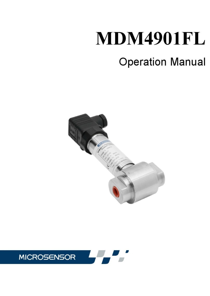
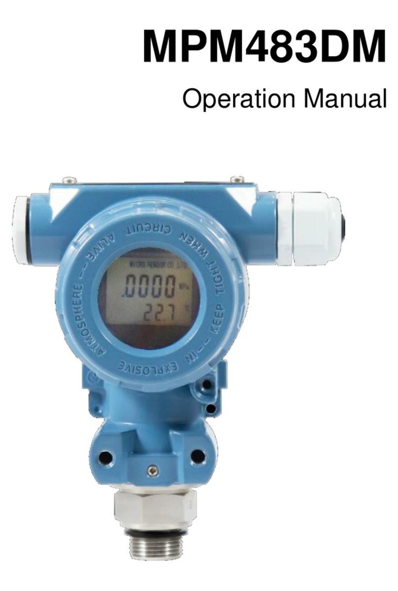
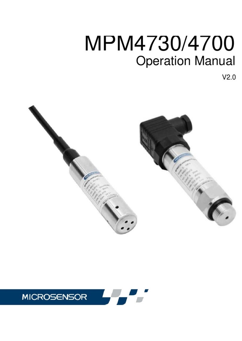
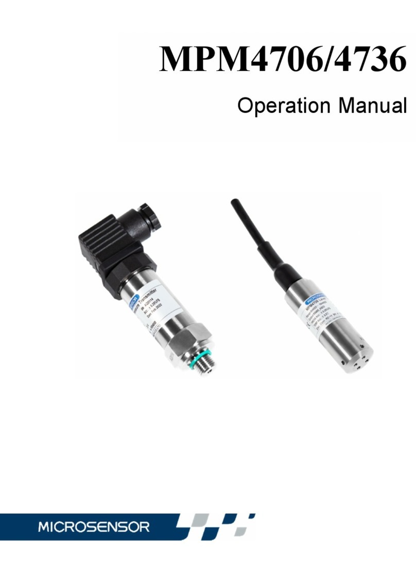
Microsensor MDM490 User manual

V1.0
MDM490
Operation Manual

1
Thanks for your using products from MICROSENSOR. MDM490 precise
piezo-resistive transmitter is one of precise instruments. We suggest you to read
this manual carefully before use.
1 Introduction
MDM490 precise piezo-resistive transmitter is a differential pressure
measurement device with compact size. The transmitter using a differential
pressure sensor and special amplified circuit, through stability and reliability
experiments, can provide standard 2-wire 4mA~20mADC and 3-wire 0/1V~
5VDC 、0mA~10mA/20mADC signal output by external power supply
24VDC, as well zero and span compensation in the wide temperature range.
The parts being contacted with the media are the stainless steel materials and
viton. The differential pressure transmitter can be used in vary industry
processing control and differential pressure, flow and level measurement, etc.
The product is manufactured in conformity to License for Manufacturing
Measurement Instrument Shaanzhi No. 03000112 of P. R. China. Products
measurement tools type approval No. 15F139-61.
2 Specifications
Pressure Range: 0kPa ~35kPa…3.5MPa
Power Supply: 15V~28VDC
Output: 2-wire 4mA~20mADC
3-wire 0/1V~5/10VDC,0mA~10/20mADC
Operation Temperature:-10~80℃(Intrinsically Safe model :-10~60℃)
Storage Temperature:-40℃~120℃

2
Static pressure:≤20MPa
Accuracy:±0.5%FS (Non-linearity, Repeatability and Hysteresis)
Response: ≤1ms
Insulation: 100MΩ,50VDC
Housing Protection: IP65
3 Outline Construction and Installation
3.1 Construction and Mounting Dimension(Unit:mm):
Fig.1 Fig.2
3.2 Installation
3.2.1 Attentions before installation:
a) The operating pressure of measuring medium is no more than the line
pressure of transmitter;
b) The differential pressure of measuring medium in the worksite is no
more than the maximum pressure.
c) For positive and negative pressure balance and convenient repair, we
recommend to use tri-valve (such as J23SA)to connect with the leading tube,

3
to prevent one-side overpressure destroying the transmitter. Or the customer can
buy the leading tube and tri-valve from our factory. Tri-valve operation method
can see appendix “Tri-valve Operation Menu”.
3.2.2 Installation Method
a) The recommended method is to see Fig. 3.
Fig. 3
b) Installation notes:
1) To prevent the installation position from affecting zero output
signal, the transmitter can be installed horizontally on the tube and the plug
could be installed vertically up.
2) Pay attention to whether the measured medium is consistent with
the transmitter structure material.
3) Pay attention to the measuring medium is compatible with the

4
construction material or not.Notice the positive(“+”) and negative (“-”)
mark on the pressure ports while connecting the actual pressure direction
corrrectly.
4) The transmitter should be installed in the low temperature
gradient and low temperature fluctuation place, to prevent vibration and
shock.
5) The protection of transmitter is IP65。
6) Prevent leak, friction and temperature difference error, to prevent
dregs settling on the tube affecting the diaphragm.
7) The transmitter has been calibrated when out of the factory, the
customer can operate the transmitter without calibration, but checking the
installation and electrical connection correct or not is necessary. The
transmitter can work when excitation is connected, but the signal output is
more reliable after 30 minutes.
8) Ban to pulling the cable violently, and to prevent the diaphragm
damaging don’t poke the diaphragm with metal still objects.
MDM490 differential pressure transmitter allows the customers to adjust
the zero and Span output signals while you own a standard pressure controller.
While adjusting, for the transmitter with plug connection, remove the socket on
the top of housing (take care not to break the cable), then trim “Zero” and
“Span” buttons to adjust. For the transmitter with cable connection, you need to
use a wrench slightly screw the cap and you will find the Zero and Span
calibrators on the top of housing. Restore them when finish.

5
MDM490 differential pressure transmitter has no movable mechanical
parts, the housing is welded,almost no need to repair. If the transmitter is fail to
work, the customer should contact with factory checking the reasons, and return
to factory for repair.
Caution:do not poke the pressure-leading hole with metal wire or something hard; and
do not press the diaphragm with finger or something sharp to protect the diaphragm.
4 Electric Connection
4.1 The transmitter is connected with the outside circuit through plug or
special cable.
The pin arrangements of socket are to see Fig.4, and pin definitions are as
follows:
Table 1
Pin
2-wire
3-wire
1
+V
+V
2
OV/+OUT
GND
3
Null
+OUT
Fig.4
The electric definitions of cable are as follow:
Table 2
Cable
2-wire
3-wire
Black
+V
+V
Red
OV/+OUT
GND
White
Null
+OUT

6
4.2 Electrical connection method is indicated as follow
4.2.1 4mA~20mADC(2-wire)
Input
DC Supply
Load
Black
Red
Ttansimtter
Fig. 5
4.2.2 0/1V~5VDC(3-wire)
Input
DC Supply
Black
White
Red
Transmitter
Fig. 6
4.3 Plug connection Operation Method:
a) If the plug has been connected with transmitter, loose the central bolt
on the top of plug with little screwdriver and pull out the plug from
transmitter.
(caution:do not take out the socket on the transmitter to protect it)
b) To disconnect the plug, please take out the central bolt on the top of
plug, then turn the plug to the bottom and insert a little flat
screwdriver into a corner signed “Lift” and give a force. The plug core

7
will be disconnected with housing.
c) To connect the cable, put the cable through the cable jack and connect
the wires with terminals on the plug core correctly (the connection
terminals are signed with clear numbers). Please choose
Φ4.5mm~7mm shield cable and connect the cable reliably to prevent
short circuit.
d) Pull the cable slightly and push the plug core into housing (a rattling
sound could be listened), then screw down the cable-fixed nut.
e) To remove the cable, loose the cable-fixed nut to relax the cable, and
operate as Item2 to disconnect the plug. Take out the cable from
terminals with little screwdriver and pull out the cable from
cable-fixed nut, then renew the connection between plug core, plug
and socket.
Caution: renew the rectangle-ring to the pre-mounting situation in order tomaintain
the protection class when connect plug and socket.
4.4 Safe explosion proof transmitter connection Operation Method
Intrinsically safe explosion proof transmitter and safe barrier form a
intrinsically safe explosion proof system, when it is operated in the
explosive conditions. The safe barrier and excitation should be put in safe
area, and intrinsically safe model transmitter should be put in hazardous
area. Notice for connected with earth safely. To see follow Fig.7.

8
Fig. 7
≤35kPa Explosion proof grade Explosion proof grade and
and parameter of transmitter:parameter of safety fence
ExiaⅡBT6 Ga ExiaⅡC
Ui=28VDC Ii=93mADC Uo=28VDC Io=93mADC
Li≈0.1mH Ci≈0.29μF Pi=0.65W Po=0.65W
>35kPa Explosion proof grade Explosion proof grade and
and parameter of transmitter:parameter of safety fence
ExiaⅡCT6 ExiaⅡC
Ui=28VDC Ii=93mADC Uo=28VDC Io=93mADC
Li≈0.1mH Ci≈0.044μF Pi=0.65W Po=0.65W
The maximum diffused capacities of cables between transmitter and safe barrier
is Cp=Co-Ci,the maximum diffused inductance is LC=Lo-Li.
The safe barrier is purchased by customers, as long as the coefficients match the
requirements above and own the explosion proof certificate.
Safe barrier’s installation and operation should see safe barrier operation menu.
When the product is operated in “Zero”area, the excitation transformer
supplied to safe barrier should conform No. 8.1 requirements of
Load
△P
I
safe
barrier
Supply
24VD
C

9
GB3836.4-2000.
Changing components and construction are not permitted, maybe it will change
the explosion proof specification.
5 Unpacking、Components and Storage
5.1 Unpacking
a) Be sure the package is completed, and the package should be put as the
sign “UP”.
b) Be sure unpacking carefully, and prevent damaging instruments or
accessories. Pay attention to the housing jacket and rubber bushing of
transmitter cable.
5.2 Enclosed
The transmitter should be enclosed when out of factory:
When out-factory, the transmitter should include:
MDM490 differential transmitter one
Electrical connection plug (insert supplied) one
Cable (cable supplied) 1.5 meter or based on order
Product operation menu one
Product certificate of quality one
Quality following card one
5.3 Storage
The transmitter should be stored in dry ventilate room, ambient temperature
-40℃~120℃and the relative humidity≤85%, no corrosive substance in the
room.

10
6 Operation、Maintenance and Responsibility
6.1 Operation
a) The user could operate the transmitter without any adjustment. Be sure
the installation and electric connection are correct.
b) The transmitter could work at once as soon as the power is supplied. But
the signal output will be more stable after 30 minutes.
6.2 Maintenance
MDM490 precise piezo-resistive transmitter is the compact measurement
device, please pay attention to the following items in the operation:
a) If the pressure-leading hole is jammed or the diaphragm is dirty, please
clean them with impregnant which is compatible with transmitter
construction material. Do not poke pressure-leading hole with hard
object or brush diaphragm.
b) Other cable in the transmitter is for our company’s adjustments, do not
connect it at will to protect the transmitter.
c) After electric connection, make sure to screw down the socket screw-cap
and cable-fixed nut.
6.3 Responsibility
Within one year from the delivery date, we shall repair or replace the instrument
with any quality fault caused by material parts or our manufacturing technique
free of charge. For non-quality malfunction during user’s operation, we are in
charge of repair. But the material cost and the shuttle transportation fees
should be borne by users.

Table of contents
Other Microsensor Transmitter manuals

Microsensor
Microsensor MPM489WZ4 User manual

Microsensor
Microsensor MPM480 User manual

Microsensor
Microsensor MPM4841 User manual

Microsensor
Microsensor MDM6000 Series User manual

Microsensor
Microsensor MPM489WZ1 User manual

Microsensor
Microsensor MDM4901FL User manual
Microsensor
Microsensor MPM4706 User manual

Microsensor
Microsensor MPM436W User manual

Microsensor
Microsensor MPM4730 User manual
Microsensor
Microsensor MPM483DM User manual