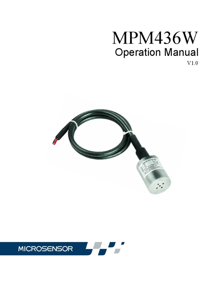
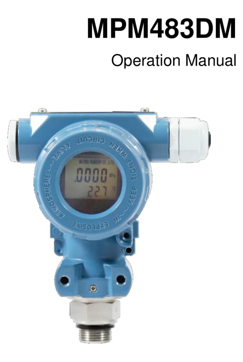
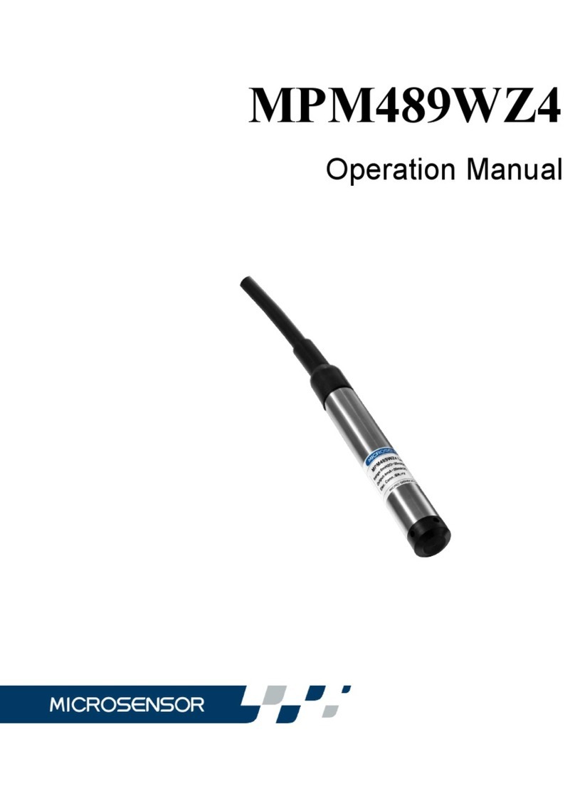
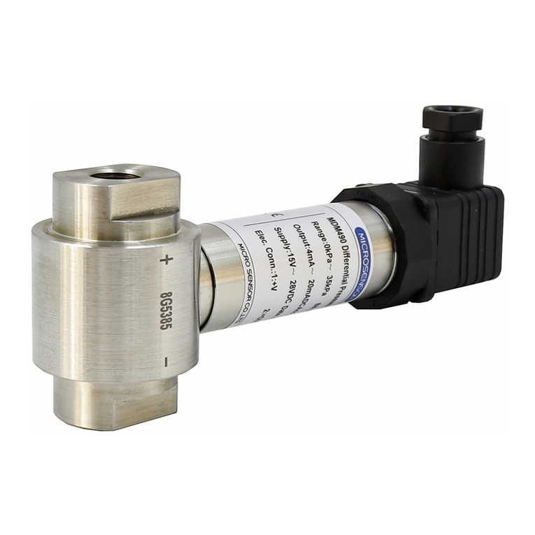
Microsensor MPM489W User manual

MPM489W
Operation Manual

Contents
1 Introduction .................................................................................... 1
2 Specifications ................................................................................. 2
3 Construction and Outline Dimension ............................................... 3
4 Operation Principle ......................................................................... 4
5 Unpacking, Storage and Shipment Enclosed .................................. 6
6 Installation ...................................................................................... 7
7 Operation, Maintenance and Fault Diagnosis................................ 15
8 Responsibility ............................................................................... 16
Our company reserves the modification right for this operation manual
due to renovation of production technology and craftwork. If some
information is changed, no more notice will be edited.
Please pay attention to the latest version.
Our company also reserves the right of final explanation for this manual.
Version: V1.0

1
Thank you very much for selecting Micro Sensor’s product, please take
some time to read this operation manual very carefully before using the
product.
1 Introduction
MPM489W level transmitter is full-sealed submersible level
measurement instrument. A high stable and dependable sensor is
mounted with the transmitter special PCB in a stainless steel housing.
The integration construction and the standard output signal support
worksite operation and automatic controlling facilities. The stainless steel
cap on the top of the transmitter protects the steel diaphragm of the
transducer, yet allows the water free access to it. The waterproof cable
sealed tightly to the housing. The reference tube is in the cable. The
housing protection is IP68, and the transmitter is available for long-term
submersible operation.
MPM489W level transmitter has advantages of small size, light weight
and long-term stability; it can be applied to measure and control in field of
petroleum, chemi-industry, medicine, metallurgy, power station, mine,
city water supply, drainage and hydrology survey, etc.
To be convenient for worksite local installation and observation, the
connection box and indicator could be assembled according to
customers’ option.

2
2 Specifications
Range: 0mH2O~1mH2O…200mH2O
Over pressure: ≤2 times FS
Pressure Type: gauge, absolute
Accuracy: ≤±0.25%FS ≤±0.5%FS ≤±1%FS
Note: The precision of products is related to the range of measurement,
and the precision of products in different range is different.
Stability Error: Range >10mH2O ≤ ±0.2%FS/year
Range ≤10mH2O ≤ ±20mmH2O/year
Temperature Drift: Zero Drift FS Drift
Range >10mH2O ≤±0.02%FS/℃ ≤±0.05%FS/℃
Range ≤10mH2O ≤±0.05%FS/℃ ≤±0.05%FS/℃
Operation Temperature:
-10℃~60℃ (Intrinsic safety)
-20℃~70℃ (cable material: PE, PVC)
-20℃~80℃ (cable material: PUR)
Storage Temperature: - 20℃~85℃
Power Supply Voltage: 11V~28V DC 3.3V/5V DC
Signal Output:
4mA~20mA DC (2-wire 11V~28V DC Power Supply)
0/1V~5V/10V DC (3-wire 11V~28V DC Power Supply)
0.5V~2.5/4.5VDC (3-wire 3.3V/5V DC Power Supply)

3
Load(Ω): RL≤ (U-11)/0.02(2-wire);≥10kΩ(3-wire)
Intrinsic safe version mark:ExiaIICT6Ga;
ExiaIICT4Ga(ATEX)
EC-Type Examination Certificate Number: Presafe 17 ATEX 11284X
Intrinsically safe coefficient:
Ui=28VDC Ii=93mA Pi=0.65W Ci=0.044uF Li=0mH
ATEX:
Ui=28VDC Ii=115mADC Li=0mH Ci=0.055uF Pi=0.66W (2-wire)
Ui=26VDC Ii=140mADC Li=0mH Ci=0.055uF Pi=0.66W (3-wire)
Ui=15VDC Ii=200mADC Li=0mH Ci=0.0451uF Pi=0.75W (3-wire)
Protection Rating :IP68
3 Construction and Outline Dimension
3.1 Construction
3.1.1 The transmitter construction to see Fig. 1:
Unit:mm
Fig. 1
3.1.2 Outline and Dimension

4
The transmitter outline dimension is to see Fig. 2.
Cable Length: assembled according to customers’ options and the
longest cable could be 300 meters.
Connection Box: Please specify a connection box is to be connected to
MPM489W when ordering.
Indicator: only for transmitter with 2-wire, 4mA~20mADC output and
connection box Ye, indicator could be provided according to the options.
Mounting hole 2-M6
Depth 10
~1 4 0
Φ8 0
Φ8 4
4 0
45
Connection box Yb Connection box Ye
54
12
SW27
10
17
108
85
85
118
35
72
38
16
Connection box Yc/Yd
Fig. 2

5
4 Operation Principle
The measuring element of transmitter is a sensor, which transfers the
pressure into electric signal by semiconductor silicon material’s
piezo-resistive effect. The measured pressure acts on stainless steel
diaphragm, and then be transferred onto sensitive chip by silicon oil
which is filled between the stainless steel diaphragm and sensitive chip
(see Fig. 3). The sensitive chip is connected with transmitter special
amplifying circuit by wires (see Fig. 4). Due to the good linearity
relationship between the electric signal of Wheatstone bridge on the
sensitive chip and the measured pressure, the pressure could be
measured accurately.
R 1
R2
R4
R3
R5
-OUT
+ OU T
+IN
-IN
+
-
blue
black
red
white
yellow
amplifying circuit
Fig. 3 Fig. 4
The basic principle of level measurement is that the liquid static pressure
which proportioned with the liquid depth is transferred into current (or
voltage) signal output, and establishing the linearity corresponding
relationship between electric signal output and the liquid depth to

6
measure level or the liquid depth.
The level measurement principle of transmitter to see Fig. 5:
Con nection Box
Control c ent er
Fig. 5
P = γ. h……………….①
P is the liquid static pressure at the measuring point;
γ is the liquid specific gravity;
h is the depth from the measuring point to the liquid surface, or level.
5 Unpacking, Storage and Shipment Enclosed
5.1 Unpacking
Attention:
a) Check the package completed or not firstly, and the box should be
put as the sign “up”.
b) Avoid knocking violently when opening, and prevent injuring
instruments or accessory. Please be carefully to prevent the
housing and rubber casing of transmitter cable from damage.
5.2 Enclosed
When out-factory, the transmitter includes:

7
MPM489W level transmitter 1
Polyethylene Special Cable(connected with transmitter)
the ordered length
Connection Box(connected with cable) due to the order
Indicator(in connection box Ye) due to the order
Product Operation Manual 1
Product Quality Certificate 1
5.3 Storage
The transmitter should be stored in dry and ventilative room with ambient
temperature -20℃~85℃,relative humidity no more than 85% and the air
in the room without corrosive gas.
6 Installation
6.1 Check before Installation
Attention before transmitter installation:
a) The static pressure produced by the liquid at installation place
exceeds the transmitter FS or not.
b) The measuring liquid is compatible with the transmitter
construction material or not.
c) The measuring liquid may stop up the holes on the protection cap
or not.
6.2 Installation Methods
The transmitter should be installed vertically down.

8
In the flowing water, the acted surface should be parallel with the water
flowing direction.
6.2.1 Installation in the Static Water
The installation method in the static water see Fig. 6.
To prevent shaking or destroying the transmitter when pumping, the
transmitter should be put away from the liquid resource. Otherwise it
should be installed as Fig. 7, protected by steel tube.
The installation method in the deep well see Fig. 7.
Steel tube inserted method is usually used. The steel tube cannot be
bent; the diameter of steel tube must be more than 30mm. Several holes
should be made at different heights on the tube so as to easily raising
and make water flow smoothly. If necessary, wrap steel wire around
transmitter to prevent breaking the cable by lifting with the steel wire.
s ed i m e n t
Electnical Connection Box
Control Room
F i x e d M o u n t
Fig. 6

9
Electnical Connection Box
Fastener
Control Room
Fig. 7
6.2.2 Installation in Flowing Water(e.g. river channel,
reservoir area, etc.)
The water-calming equipments are required.
Method one: Insert a steel tube in the water channel (see Fig. 8).
The steel tube wall should be thicker, and several holes should be made
at different heights on the tube to damp waves and clear the water
pressure influence.
Method two: Superficial burying is better in the sand and stone channel.
(see Fig.9).

10
Electnical Connection Box
Fig. 8
ELectnical Connection Box
Fig. 9
Method three: see Fig. 10.

11
Damper
Air Pocket
This method can not only clear water flowing pressure and wave
influence, but also filter the sand and mud.
Fig. 10
6.3 Electrical Connection
Wires could be connected based on terminal definitions on production
quality certificate. The specific method is to see following steps.
6.3.1 Electrical connection method
Electrical connection method of transmitter with Two-wire 4mA~20mA
DC output, to see Fig. 11. (Cable connection) Three-wire
0~5VDC/1~5VDC/0.5~4.5VDC output, to see Fig.12.(Cable connection)
P
I
P/I Transmitter
P
Input 0V/OUT
+V +
U
DC current
+
-
-
R
Load
I
4mA
~
20mA
Fig. 11

12
P
I
P/U Transmitter
P
Input +OUT
+V +
U
DC current
+
-
-
U
0/1V
~
5V
GND
Fig. 12
The electric definitions of cable are as follow:
6.3.2 The Electrical Connection Method of Explosion Proof
Version Transmitter
Intrinsically safe version explosion proof transmitters conform Standard
GB3836.1 and GB3836.4, used for explosive condition. When electric is
connecting, the transmitter and safe barrier should set up intrinsically
safe explosion proof system.
The diffused inductance and capacity between the transmitter and safe
barrier should be no more than 0mH and 0.044uF respectively. The safe
barrier and excitation should be installed in safe area, and intrinsically
Cable 2-wire 3-wire
Red +V +V
Black +OUT +OUT
White Null GND

13
safe version transmitter and connection box should be put in dangerous
area, besides the transmitter connected to the earth safely.
P
I
Dangerous Area
+V
OV
Safe
Barrier Load
Power
24VDC
+
-
Safe Area
P
Input
ExiaIICT6Ga [Exia]IIC
Fig. 13
Transmitter ex-proof parameter: Safe barrier ex-proof parameter:
Ui=28VDC Ii=93/115mADC(ATEX)mADC Uo=28VDC
Li=0mH Ci=0.0440/055μF(ATEX) Io=93/115mA DC (ATEX)
Pi=0.65/0.66W(ATEX) Po=0.65/0.66W(ATEX)
ATEX(3-wire):
Dangerous Area Safe Area
Transmitter ex-proof parameter: Safe barrier ex-proof parameter:
Ui=26VDC Ii=140mADC Uo=26VDC Io=140mADC
Li=0mH Ci=0.055μF Pi=0.66W Po=0.66W

14
Ui=15VDC Ii=200mADC Uo=15VDC Io=200mADC
Li=0mH Ci=0.0451μF Pi=0.75W Po=0.75W
Fig. 14
The maximum diffused capacities of cable between the transmitter and
safe barrier is Cp = Co-Ci,and diffused inductance is Lp = Lo-Li。
6.3.3 The electrical connection method of transmitter with
junction box.
There is terminal block inside of the junction box. Please refer the
defination of the electrical wiring connection as indicated 。
6.4 The Reference Tube Installation
There is a plastic tube in the transmitter special cable; the back pressure
cavity of gauge sensor is connected to atmosphere by this tube. In the
process of installation and operation, be sure to keep the reference tube
be well connected with the atmosphere. Mud or sand should not be
jammed into the reference tube. Prevent water or other liquid going
through the reference tube to destroy the transmitter.
6.5 Attentions
a) Transmitter should be installed vertically downwards.When used in
moving water,it must be noted that parallel to direction of the flow
of water.
b) There is a plastic tube (the reference tube) in the special
transmitter cables to connect the atmosphere. In installation and
operation, connect the reference tube with the atmosphere

15
unobstructed and prevent mud and sand stopping up the
reference tube, especially water or other liquid. Otherwise, the
transmitter would be destroyed.
c) If the transmitter is mounted under thunder-lightning situation, we
suggest having an additional lightning-arrester in the cables.
7 Operation, Maintenance and Fault Diagnosis
7.1 Operation
The customer could operate the transmitter without adjustment.
Please be sure that the installation and electrical connection are correct
or not before operation.
Connect the excitation and operate.
The transmitter could work at once as soon as it is connected with
excitation, but the output signal could be more reliable after 30 minutes.
7.2 Maintenance
MPM489W level transmitter does not need to be maintained regularly,
but please pay attention to items as follow for better operating effect and
reliability.
a) Check wire connection is reliable or not, and the cable is broken
and old or not.
b) Clean the protection cap and diaphragm cavity periodically.
(take care!)
c) Don’t violently pull cables or poke the diaphragm with metal or

16
other hard objects.
7.3 Fault Diagnosis
MPM489W level transmitter is integrative full-sealed construction without
movable parts inside, owning advantage of long-term stability and
reliability.
If some failure occur, such as no output, output too big or too small and
unreliable, please turn off the excitation firstly, then check the installation
and wire connection conform with the operation manual or not, the
excitation is correct or not and the reference tube is unobstructed or not.
If unsuccessful, the transmitter may be destroyed, please contact our
company.
8 Responsibility
Within one year from the delivery date, we shall repair or replace the
instrument with any quality fault caused by material parts or our
manufacturing technique free of charge. For non-quality malfunction
during user’s operation, we are in charge of repair. The material cost and
the shuttle transportation fees should be borne by users.


Table of contents
Other Microsensor Transmitter manuals

Microsensor
Microsensor MDM4901FL User manual

Microsensor
Microsensor MPM4730 User manual

Microsensor
Microsensor MPM4706 User manual

Microsensor
Microsensor MPM480 User manual

Microsensor
Microsensor MPM489WZ1 User manual

Microsensor
Microsensor MPM483DM User manual

Microsensor
Microsensor MPM489WZ4 User manual

Microsensor
Microsensor MPM436W User manual

Microsensor
Microsensor MPM489WZ3 User manual
Microsensor
Microsensor MPM426W Series User manual