Microsensor MPM4706 User manual

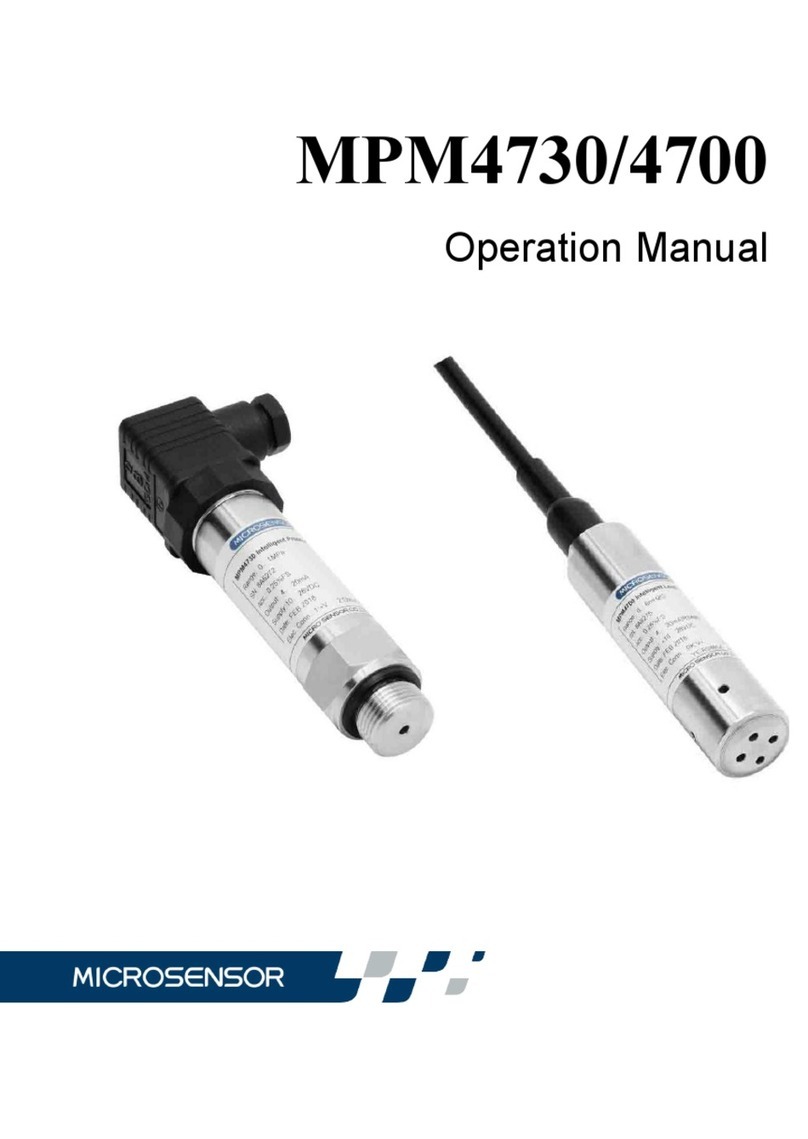
MPM4706/4736
Operation Manual

Our company reserves the modification right for this operation manual
due to renovation of production technology and craftwork. If some
information is changed, no more notice will be edited.
Please pay attention to the latest version.
Our company also reserves the right of final explanation for this manual.
Version: V1.0

1
Thank you for choosing Micro Sensor products. Please read this manual
carefully before use.
1 Introduction
MPM4736/4706 transmitter is a highly precise and stable digital
transmitter for the pressure/level measurement. This product utilizes the
highly reliable piezoresistive OEM pressure sensing element and the high
precision digital processing circuit, coupled with a dedicated algorithm, the
transmitter is capable of high precision measurement. The product
supports the measurement of both pressure and temperature and
communicate via an RS485 interface. The transmitter consumes very low
power and automatically enters standby mode when not communicating,
and the power consumption at standby mode is as low as 10uA.
2 Specification
Measured range: -1bar...0bar~0.1bar...1000bar (MPM4736)
0 mH2O ~1 mH2O...200mH2O(MPM4706)
Over pressure: ≤2 times FS or 1100bar(Min. value is valid)
Pressure Type: guage, absolute, sealed gauge(MPM4736)
guage, absolute(MPM4706)
accuracy: ≤±0.25%FS ≤±0.5%FS ≤±1%FS
Note: The precision of products is related to the range of measurement,
and the precision of products in different range is different.
Temperature accuracy (ambient temperature):

2
±0.5℃ (-20℃~80℃) (MPM4736&MPM4706))
±0.75℃(-30℃~-20℃) (MPM4736)
Power supply: 3.6V~28V DC
Output signal: RS485 interface, MODBUS RTU/ ASC II
Operation temperature:
-30℃~80℃(MPM4736 4-pin Plug and MPM4736 7-pin Plug)
-20℃~70℃(MPM4736 and MPM4706 cable material: PE, PVC)
-20℃~80℃(MPM4736 and MPM4706 cable material: PUR)
Storage temperature: -40℃~85℃(MPM4736 4-pin Plug and MPM4736
7-pin Plug)
-20℃~85℃(MPM4736 cable and MPM4706)
Long-term stability: ±0.25%FS/year
Baud rate: 1200, 2400, 4800, 9600 optional
Load capacity: RS485 terminal can cascade up to 99 transmitters
Insulation resistance: 100MΩ@500V DC
Protection rating: IP65 (MPM4736)
IP68 (MPM4706)
Cable: Φ7.5mm polyethylene (or polyurethane) vented cable
3 Outline and Installation
Unit: mm

3
See dimension below
MPM4706
MPM4736
4 Electrical Connection
4.1 Transmitter electrical connection diagram see below
50
M20×1.5
12
SW27
(120)
SW19
27
M20×1.5
12
SW27
(105)
27
M20×1.5
12
SW27
(96)
27
B1 4-pin Angular
Connector Model
B2 Cable outlet
model
B3 7-pin Aviation
plug model
(103)
16
26
5.5
4× 3EQS

4
Table 1.
Table 1
Connection
Electrical Connection
Angular
Connector
Pin Code
MPM4736
Cable
outlet/MPM470
6
7-PIN
Aviation Plug
+V 1 Red 1
-V 2 Black 2
RS485B White 5
RS485A 3 Yellow (Green)
4
4.2 Installation Notes
The gauge pressure type submersible level transmitter includes a plastic
vent tube which connects the back-pressure cavity of the gauge sensor
to the atmosphere. In the process of installation and operation, care
should be taken that the vent tube be well connected with the
atmosphere. Always be careful that the vent tube is not jammed, and
make sure no water or other liquid flows through the vent tube. Otherwise,
failure to protect the vent tube could result in premature failure of the
transmitter.
4.3 RS485 Communication Software

5
The MS Setonline communication software can be used to read the
basic information (including level range and temperature compensation
range, version, etc.) of the transmitter with RS485 interface, display the
actual level value, set the new zero point, configure the analog output,
and set the instrument address with the assistance of a RS485
conversion module.
Note: The "MS Setonline " software can be downloaded from Micro
Sensor website.
4.3.1 How to use RS485 Communication Software and
Precautions
4.3.1.1 Transmitter Parameters Reading Method

6
a) Connect power to the transmitter correctly in accordance with the
Table 1 connection diagram in Section 4.1.
b) Then connect the RS485 communication line with the RS485
communication module as per the diagram of Table 1 in Section 4.1.
c) Following the above 2 steps, connect the RS485 module to the
computer, then run the "47XX" communication software, click on the
"Refresh", select correct " Serial Port". "The serial port number
should be consistent with the port number of the RS485
communication module used in the "Device Manager" of the
computer and click on "Protocol" in the upper left corner of the
software interface and select " R4-ASCII" or "R8-MODBUS" based
on the sensor module.
d) After selecting the correct serial port number, choose the baud rate
of the product (the factory default baud rate is "9600"), and click the
"Open Serial Port" button, then click the "Search" button. The
software will automatically search for the transmitter, and when the
transmitter is found, the bottom of the software will prompt the online
transmitter number "X online".
e) The real-time pressure and temperature values can be displayed by
clicking the "Acquisition" button.
4.3.1.2 How to Modify Transmitter Parameters?
After the "47XX" software reads the product parameters successfully, if
users need to modify the product parameters, please refer to the
following methods.
a) Zero Adjustment: when there is a slight shift in the zero-pressure

7
output, for example: a Gauge pressure sensor should display "0"
pressure in the atmospheric environment, but the actual reading may
be greater than or less than "0". The user can click " Zero" button to
zero the transmitter, the reading will be changed to "0" after the Zero
adjustment.
b) To configure the transmitter address, baud rate and other
parameters, change the parameters to be modified to the target
values in the "Basic Info" column, and then click the "Modify" button
to re-search for the transmitter.
c) No change needs to be made to "Digital Output Signal Set" and
"Analog Output Set"
d) "Command " is similar to the function of serial assistant, the RS485
communication function will be implemented directly in string form or
in HEX, the software will automatically add Check Start-bit and
Stop-bit, and the complete command will be displayed in Send
Buffer.
Note: After the parameter’s modification is completed, please click the
"Save Modification" button to write the modified parameters to the
transmitter, otherwise all parameters will return to the state before
modification after the transmitter is re-connected to power.
4.3.2 RS485 Communication Failure Self-inspection
a) First be sure the wiring connection is correct.
b) Then ensure that the power supply voltage of the transmitter is within
the normal operating voltage range.

8
c) Before operation, it is recommended to use the "47XX" host
computer on the computer to read the parameters of the transmitter
to ensure that the product does not have any communication
problem, and make sure the address and other parameters of the
product are proper as well. If the host computer fails to find the
transmitter, please check that the RS485 communication module
port is the same as the selected one and confirm that the RS485
module driver is correctly installed. It is suggested to use the USB to
RS485 converter directly and not to convert the USB to RS232 then
to RS485 converter.
d) When communicating with the transmitter via the commands, if the
communication fails, please check, and make sure the product
address, function code, CRC check are correct. The commands
used by the transmitter can be found in the command set, please
strictly follow the instructions in the command set communicate with
the transmitter.
5 Unpacking, Shipment Enclosed and Storage
5.1 Unpacking
a) Check the package for shipping damage and be careful it is placed
with right side facing upward.
b) When opening the box, please be careful to protect the housing and
rubber casing of the transmitter cable from being damaged.

9
5.2 Shipment Enclosed
The contents of the package include:
MPM4736 Digital Pressure Transmitter 1pc
(or MPM4706 Digital Level Transmitter 1pc)
Special Electrical Connecto2r (for Plug Connection Type) 1pc
Cable (MPM4736 cable type &MPM4706) And Length By contract
Junction Box (connected to cable) By contract
Operation Manual 1pc
Certificate of Compliance 1pc
Converter By contract
5.3 Storage
The transmitters storage temperature range should be within -40℃~85℃
(MPM4736 4-pin Plug and MPM4736 7-pin Plug) -20℃~85℃
(MPM4736 cable and MPM4706) with the relative humudity level less
than 85%, and there is no presence of corrosive gases.
6 Responsibility
Micro Sensor products are warranted for a period of one year
commencing from the date of shipment to the original purchaser. Within
the warranty period, the instruments with failures due to defects in
material and workmanship will be repaired or replaced without charge;
For non-quality failure during user’s operation, repair service can be
provided, but the material and the double-way transportation cost should
be borne by purchasers.

This manual suits for next models
1
Table of contents
Other Microsensor Transmitter manuals

Microsensor
Microsensor MPM489WZ4 User manual

Microsensor
Microsensor MPM4730 User manual

Microsensor
Microsensor MDM6000 Series User manual

Microsensor
Microsensor MPM436W User manual

Microsensor
Microsensor MPM489W User manual

Microsensor
Microsensor MPM489WZ1 User manual

Microsensor
Microsensor MPM489 User manual

Microsensor
Microsensor MDM490 User manual

Microsensor
Microsensor MPM426W Series User manual
Microsensor
Microsensor MPM483DM User manual