Microtronics BLE Gauge User manual

300909 | Rev.02
Cover
Valid from:
lFirmware version: 01v000
lServer version: ---
lHardware version: 1.1
User manual
BLE Gauge


Chapter 1 Table of contents
Cover 1
Chapter 1 Table of contents 3
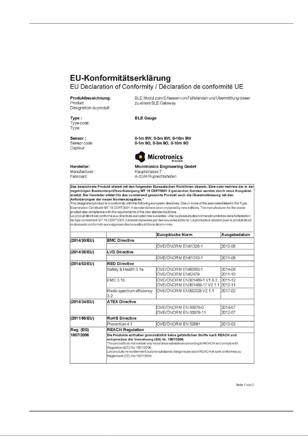
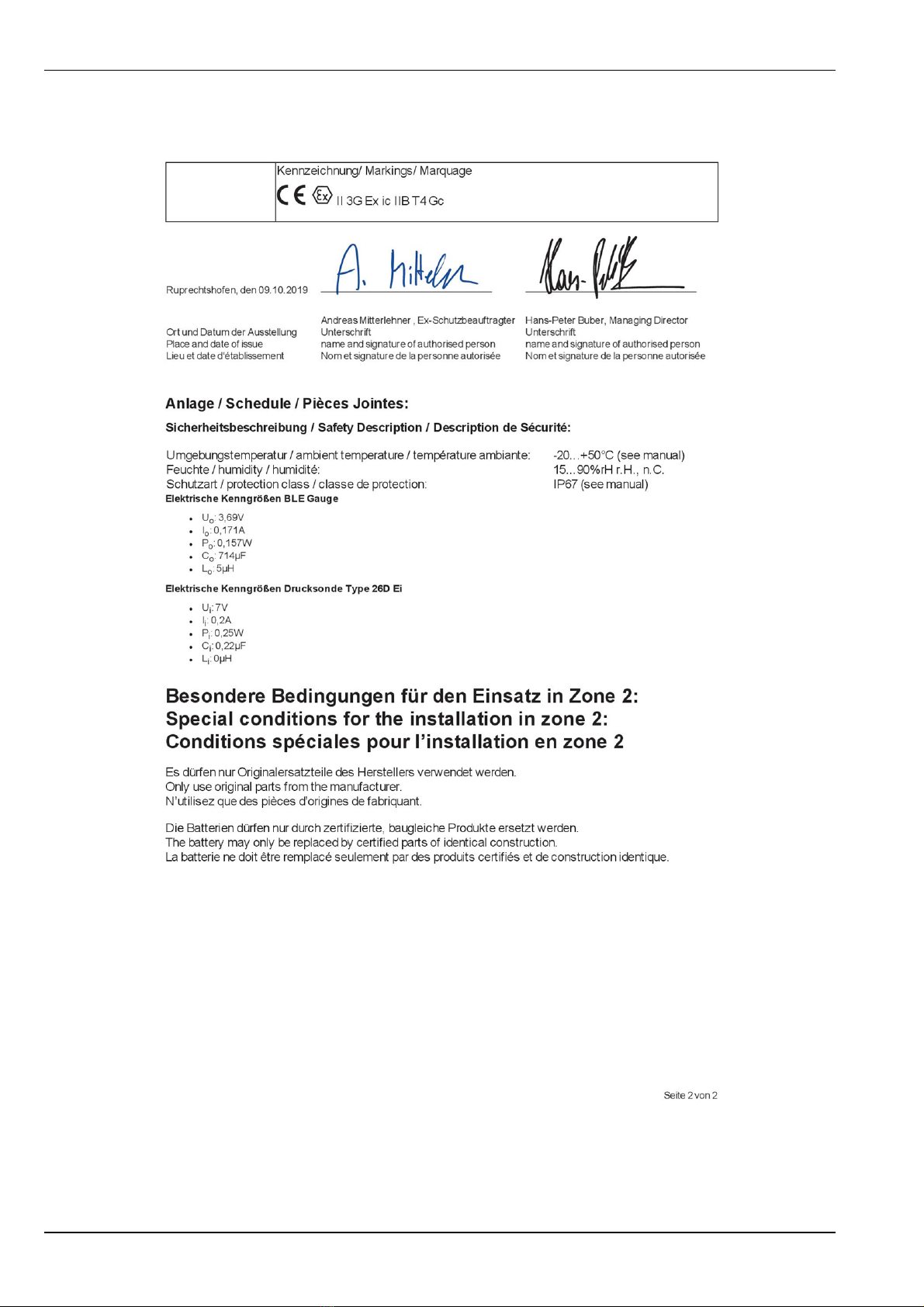
Chapter 2 Declaration of conformity 7
Chapter 3 Specifications 9
3.1 Applicable regardless of the selected pressure sensor 9
3.2 BLE Gauge pressure sensor 0-1m 9W (300872) 9
3.3 BLE Gauge pressure sensor 0-3m 9W (300871) 10
3.4 BLE Gauge pressure sensor 0-10m 9W (300891) 10
Chapter 4 General specifications 11
4.1 Translation 11
4.2 Copyright 11
4.3 General descriptive names 11
4.4 Ex protection 12
4.5 Safety instructions 12
4.5.1 Use of the hazard warnings 13
4.5.2 General safety instructions 13
4.5.3 Safety and preventative measures for handling Bluetooth modules 13
4.5.3.1 Safety and precautionary measures for the Bluetooth module installation 14
4.6 Overview 14
4.6.1 Block diagram 15
4.7 Intended use 15
4.8 General product information 15
4.9 Device labelling 16
4.10 Installation of spare and wear parts 17
4.11 Storage of the product 17
4.12 Obligation of the operator 18
4.13 Personnel requirements 18
Chapter 5 Functional principle 19
5.1 Determining the fill level 20
5.1.1 Determining the raw value (relative pressure) 20
5.1.2 Calculating the fill level 20
Rev. 02 3

5.1.3 Taking the installation height into consideration 21
5.1.4 Taking the trimming into consideration 21
Chapter 6 Storage, delivery and transport 23
6.1 Inspection of incoming deliveries 23
6.2 Scope of supply 23
6.3 Storage 23
6.4 Transport 23
6.5 Return 23
Chapter 7 Installation 25
7.1 Dimensions 25
7.2 Installing the BLE Gauge 25
7.2.1 Suspended installation 26
7.2.2 Earthing of the BLE Gauge when installed suspended 30
7.3 Electrical installation 31
7.3.1 Technical details about the Bluetooth Low Energy interface 31
Chapter 8 Initial Start-Up 33
8.1 User information 33
8.2 General principles 33
8.3 Placing the system into operation 33
8.3.1 Use in conjunction with a compatible data logger 33
8.3.1.1 Using the myDatanet server 33
8.4 Testing communication with the device 36
8.4.1 Testing communication between the BLE Gauge and the data logger 36
Chapter 9 User interfaces 39
9.1 Display of a compatible data logger 39
9.2 Site configuration of a compatible data logger 39
9.2.1 Site 40
9.2.2 Measurement channels 41
9.2.2.1 Basis 41
9.2.2.2 Alarms 42
9.2.2.3 Trigger 43
Chapter 10 DeviceConfig 45
10.1 General 45
4Rev. 02

Chapter 1 Table of contents
10.2 Prerequisites 45
10.3 Functional principle 46
10.3.1 USB BLE-Adapter 47
10.4 Installation 47
10.4.1 Installing the drivers for the USB BLE-Adapter 49
10.5 Menu of the DeviceConfig 50
10.5.1 Settings 50
10.5.1.1 Options 50
10.6 Establishing a connection to a sensor module with Bluetooth Low Energy interface 51
10.7 "Firmware" tab 53
Chapter 11 GaugeBuster 55
Chapter 12 Maintenance 57
12.1 General maintenance 57
12.2 Replacing the battery 57
Chapter 13 Removal/disposal 59
Chapter 14 Troubleshooting and repair 61
14.1 General problems 61
Chapter 15 Spare parts and accessories 63
15.1 Data logger 63
15.2 Installation sets 63
15.3 Pressure sensors 63
Chapter 16 Document history 65
Chapter 17 Glossary 67
Chapter 18 Contact information 69
Rev. 02 5


Chapter 2 Declaration of conformity
Rev. 02 7

8Rev. 02

Chapter 3 Specifications
3.1 Applicable regardless of the selected pressure sensor
Voltage supply Battery: Li-SOCl2 cell with 1,2Ah
Housing Material: POM / Stainless Steel (BLE Gauge / pressure sensor)
Weight: approx. 270g (incl. pressure sensor and 5m cable)
Protection class: IP67
Dimensions (DL): 40 x 100mm / 21 x 74mm (BLE Gauge / pressure sensor)
Ex certification
II 3G Ex ic IIB T4 Gc
Operating temperature -20...+50°C
Air humidity 15...90%rH non-condensing
Storage and transport
temperature
-20...+50°C
Temperature sensor Measurement range: -20...+50°C 1)
Resolution: 0,05°C
Data type Fill level [mm]: s16 (16Bit signed)
Temperature [0.05°C]: s16 (16Bit signed)
Data transmission Bluetooth Low Energy:
Range: 20m (depending on the environmental conditions)
Device operating time up to 5 years (depending on the measurement cycle)
1) The compensation of the temperature-related influences on the fill level measurement only occurs in the range of
0...50°C .
3.2 BLE Gauge pressure sensor 0-1m 9W (300872)
Measurement range 0-1m
Resolution 1mm
Cable length 5m
suitable for Fresh, waste and grey water
Measurement method Piezoresistive pressure sensor
Rev. 02 9

3.3 BLE Gauge pressure sensor 0-3m 9W (300871)
Level 0-3m
Resolution 1mm
Cable length 5m
suitable for Fresh, waste and grey water
Measurement method Piezoresistive pressure sensor
3.4 BLE Gauge pressure sensor 0-10m 9W (300891)
Level 0-10m
Resolution 1mm
Cable length 12m
suitable for Fresh, waste and grey water
Measurement method Piezoresistive pressure sensor
10 Rev. 02

Chapter 4 General specifications
The information in this manual has been compiled with great care and to the best of our knowledge. The
manufacturer, however, assumes no liability for any incorrect specifications that may be provided in this
manual. The manufacturer is not responsible for direct, indirect, accidental or consequential damages which
arise from errors or omissions in this manual even if advised of the possibility of such damages. In the interest
of continuous product development, the manufacturer reserves the right to make improvements to this
manual and the products described in it at any time and without prior notification or obligation.
Note: The specifications in this manual are valid as of the versions listed on the front page. Revised versions
of this manual, as well as software and driver updates are available in the service area of the myDatanet
server.
4.1 Translation
For deliveries to countries in the European Economic Area, the manual must be translated into the language
of the respective country. If there are any discrepancies in the translated text, the original manual (German)
must be referenced or the manufacturer contacted for clarification.
4.2 Copyright
The copying and distribution of this document as well as the utilisation and communication of its contents to
others without express authorisation is prohibited. Contraventions are liable to compensation. All rights
reserved.
4.3 General descriptive names
The use of general descriptive names, trade names, trademarks and the like in this manual does not entitle
the reader to assume they may be used freely by everyone. They are often protected registered trademarks
even if not marked as such.
Rev. 02 11

4.4 Ex protection
The portable BLE Gauge is designed for use in areas with a zone2 explosive atmosphere.
The following conditions must be observed:
lOnly the manufacturer is permitted to open the housing to carry out maintenance work, which must
only be completed outside the Ex area.
lThe battery must only be replaced by the manufacturer with certified identical products.
lOnly the manufacturer is permitted to replace the pressure sensor.
lOnly the manufacturer's original spare parts must be used.
lDue to the electrostatic effects, the device must not be rubbed with cloths in the Ex zone.
lA mounting distance of min. 50mm must be maintained on all sides to prevent any impurities.
II 3G Ex ic IIB T4 Gc
Important note: The Ex approval is only valid if the corresponding marking is provided on the type
plate of the module .
Important note: The certificates of conformity and any relevant test certificates from the respective
authorities must be carefully observed during installation and commissioning.
1BLE Gauge
4.5 Safety instructions
For the connection, commissioning and operation of the BLE Gauge , the following information and higher
legal regulations of the country (e.g. ÖVE), such as valid EX regulations as well as the applicable safety and
accident prevention regulations for the respective application case must be observed.
Read this manual completely before unpacking, setting up or operating this device. Observe all hazard,
danger and warning information. Non-observance can lead to serious injuries to the operator and/or damage
to the device.
Ensure that the safety equipment of this measurement instrument is not impaired. Install and use the
measurement system only in the manner and method described in this manual.
Important note: The manufacturer's products that are designed for use outdoors include extensive
protection against penetrating moisture and dust.
12 Rev. 02

Chapter 4 General specifications
4.5.1 Use of the hazard warnings
DANGER:
Indicates a potential or threatening hazardous situation that will result in death or serious
injuries if not avoided.
WARNING:
Indicates a potential or threatening hazardous situation that can result in death or serious
injuries if not avoided.
CAUTION:
Indicates a potential hazardous situation that can result in minor or moderate injuries or
damage to this instrument.
Important note: Indicates a situation that can result in damages to this instrument if it is not avoided.
Information that must be particularly emphasised.
Note: Indicates a situation that does not result in any injury to persons.
Note: Information that supplements the specifications in the main text.
4.5.2 General safety instructions
WARNING:
Never use this device in areas where the use of wireless equipment is prohibited. The
device must not be used in hospitals and/or in the vicinity of medical equipment, such as
heart pacemakers or hearing aids, as their functionality could be compromised by the
Bluetooth modulecontained in the device.
4.5.3 Safety and preventative measures for handling Bluetooth modules
The following safety and preventative measures must be observed during all phases of installation, operation,
maintenance or repair of a Bluetooth module. The manufacturer is not liable if the customer disregards these
preventative measures.
CAUTION:
The Bluetooth connection must not be used in hazardous environments.
No guarantee of any kind, whether implicit or explicit, is given by the manufacturer and its suppliers for the use
with high risk activities.
In addition to the following safety considerations, all directives of the country in which the device is installed
must be complied with.
Rev. 02 13

4.5.3.1 Safety and precautionary measures for the Bluetooth module installation
lThe device must not be operated in hospitals and/or in the vicinity of medical equipment such as heart
pacemakers or hearing aids.
lThe device must not be subjected to strong vibrations or impacts.
lDo not open the Bluetooth module. Any modification to the device is prohibited and will result in the
operating licence being revoked.
lDo not install the device in any other way to the one described in the operating instructions. Improper
use will invalidate the warranty.
4.6 Overview
Top of the BLE Gauge
Left side of the BLE Gauge (incl. pressure sensor)
1Pressure compensation 2Medium inlet openings
3Pressure sensor
14 Rev. 02

Chapter 4 General specifications
4.6.1 Block diagram
Block diagram of the BLE Gauge
4.7 Intended use
The portable measurement instrument is designed to record fill levels. The device is battery-operated.
Current measurement values can be read out via a Bluetooth connection (Bluetooth Low Energy) and can
either be displayed via a smartphone app or recorded using a compatible data logger. The maximum
permissible limit values (specified in chapter "Specifications" on page 9) must be observed. The manufacturer
shall not be liable for any operational cases that deviate from these limit values and have not been approved
by the manufacturer in writing.
Note: This device is exclusively intended to be used for the purposes as described before. Any other
use or use beyond what is specified or a modification of the device shall be deemed to be not for the
intended purpose and is not permitted without the express written consent of the manufacturer. The
manufacturer shall not be held liable for any damages that may result from such unauthorised use or
modification. The operator alone bears the associated risk.
Note: The manufacturer is not liable for data loss of any kind.
4.8 General product information
The device is a compact, portable measurement system used to determine fill levels that consists of a
pressure sensor and a transmission unit. The BLE Gauge is equipped with an internal battery to supply the
integrated logic (BLE module, controller and pressure sensor). The capacity of the installed battery is
designed for a max. service life of 5 years. In addition to the fill level (taking the installation height and trimming
into consideration), the internal measurement values "Pressure" (raw value), "PowerOn Flag" (sensor
status), "Battery Sensor" and "Sensor Temp." are determined. This measurement data is determined once
every minute and can be read out via a Bluetooth connection (Bluetooth Low Energy) and can either be
displayed via the smartphone app or recorded using a data logger. An external system (data logger or
smartphone app) can also be coupled with the BLE Gauge (BLE pairing). In this case, determining the
measurement data must be initiated by the external system (data logger or smartphone app). Measurement
values generated in this way, can then be read out and can either be displayed via a smartphone app or
recorded using a data logger. A list of compatible data loggers is provided in the chapter "Data logger" on
page 63. A Bluetooth Low Energy compatible smartphone and the "GaugeBuster" smartphone app are
Rev. 02 15

required to display the current measurement values. The smartphone app can also be used to transmit the
configuration values for the installation height and trimming to the BLE Gauge .
4.9 Device labelling
The information in this user manual applies exclusively to the measurement system that consists of the
following components:
lBLE Gauge
lPressure sensor
The type plates of the BLE Gauge are located on the top and sides of the device and contain the following
specifications:
lType designation
lSerial number
lHardware revision
lItem number
lEx protection designation as specified in chapter"Declaration of conformity" on page 7
lWeek and year of production
lEnvironmental conditions during operation
lProtection class
lName and address of the manufacturer
lChemical composition of the installed battery
lLogo for the EU WEEE Directive
lCE marking
lEx parameters as specified in chapter"Declaration of conformity" on page 7
Type plates BLE Gauge
16 Rev. 02

Chapter 4 General specifications
The type plate of the pressure sensor is located on the upper end of the cable and contains the following
specifications:
lItem number
lMeasurement range (e.g. 0-10m)
lType of pressure sensor (e.g. "9" for series PR-26D Ei)
lPermissible media (e.g. "W" for fresh, waste and grey water)
Type plate of the pressure sensor
The correct specification of the type designation and serial number is important for all queries and spare part
orders. Only then can we process requests promptly and properly.
Note: These operating instructions are part of the device and must be available to the user at all
times. The safety instructions contained therein must be observed.
WARNING:
It is strictly prohibited to disable the safety equipment or modify its mode of operation.
4.10 Installation of spare and wear parts
Be advised that spare and accessory parts that have not been supplied by the manufacturer have also not
been inspected or approved by the manufacturer. The installation and/or use of such products can possibly
have a negative impact on the specified constructional properties of the device. The manufacturer shall not be
liable for any damages that arise from the use of non-original parts and non-original accessory parts.
Note: The use of spare and wear parts that are not approved by the manufacturer shall void the Ex
approval.
4.11 Storage of the product
The BLE Gauge does not include a special transport mode. The capacity of the installed battery is designed
for a max. service life of5 . In the event of unfavourable environmental conditions (e.g. low temperatures), it
may occur that the battery capacity is depleted before this period of time has elapsed. Store the BLE Gauge in
its original packaging.
Rev. 02 17

4.12 Obligation of the operator
WARNING:
In the EEA (European Economic Area), the national implementation of the framework
directive (89/391/EEC) as well as the associated specific directives and from these in
particular, the directive (2009/104/EC) about the minimum safety and health requirements
for use of work equipment by workers at work, each in their respective version are to be
complied with.
The operator must obtain the local operating licence and the associated documents.
In addition, the operator must comply with the local legal requirements for
lthe safety of the personnel (accident prevention measures),
lthe safety of the equipment (protective equipment and maintenance),
lthe product disposal (waste disposal law),
lthe material disposal (waste disposal law),
lthe cleaning (cleaning agents and disposal) and
lthe environmental protection amendments.
Before commissioning, the operator must ensure that the installation and commissioning – provided these
were performed by the operator himself – are in compliance with the local regulations.
4.13 Personnel requirements
Installation, commissioning and maintenance may only be completed by personnel who meet the following
conditions:
lQualified specialist personnel with the relevant training
lAuthorised by the facility operator
Note: Qualified personnel
In the context of these instructions and the warnings on the product itself, individuals responsible for the setup,
installation, commissioning and operation of the product must have gained relevant qualifications relating to
their activities, including, for example:
lTraining, instruction and authorisation to activate/deactivate, ground and label electric circuits and
devices/systems in accordance with the standards of safety engineering.
lTraining or instruction on the maintenance and use of suitable safety equipment in accordance with the
standards of safety engineering.
lFirst aid training
18 Rev. 02

Chapter 5 Functional principle
Functional principle
1BLE Gauge (incl. pressure sensor) 2Smartphone with "GaugeBuster" smartphone app
installed
3Compatible data logger (e.g. myDatalogGauge
3G ATEX)
Functions and components:
lBLE Gauge (incl. pressure sensor)
The device is a portable measurement instrument approved for Ex zone 2 for determining fill levels.
The transmission of measurement commands to the BLE Gauge and reading out of the determined
measurement values from the BLE Gauge are realised via a Bluetooth connection (Bluetooth Low
Energy).
Rev. 02 19

l"GaugeBuster" smartphone app
When used in conjunction with a Bluetooth Low Energy compatible smartphone, the "GaugeBuster"
smartphone app enables you to start a measurement and display the subsequently generated
measurement values of the BLE Gauge . The smartphone app can also be used to transmit the
configuration values for the installation height and trimming to the BLE Gauge .
lCompatible data logger (e.g.myDatalogGauge 3G ATEX)
Data logger that cyclically starts the fill level measurement and then records the generated
measurement values. A list of compatible data loggers is provided in the chapter "Data logger" on page
63.
5.1 Determining the fill level
Diagram of how the "Level" measurement value is generated
1Generation of the raw value, which is the relative
pressure (see "Determining the raw value
(relative pressure)" on page 20)
3Adds the value entered via the "Sensor Offset"
configuration parameter to the fill level (see
"Taking the installation height into consideration"
on page 21)
2Conversion of the raw value (relative pressure) to
the fill level (see "Calculating the fill level" on page
20)
4Adds the value entered via the "Trimming"
configuration parameter to the fill level that is
corrected by the "Sensor Offset" (see "Taking the
trimming into consideration" on page 21)
5.1.1 Determining the raw value (relative pressure)
The raw value is the relative pressure read directly by the pressure sensor that is also available as the internal
measurement value "Pressure". In the range of 0...50°C , the pressure sensor controller automatically
compensates the temperature-related influences. If no external system (data logger or smartphone app) is
coupled with the BLE Gauge (BLE pairing), the raw value is automatically determined once per minute.
However, if a coupling has been established, determining the raw value (i.e. relative pressure) must be
initiated by the external system (data logger or smartphone app) that communicates with the BLE Gauge via
a Bluetooth connection (Bluetooth Low Energy). The measurement cycle is thus specified by the external
system but must not fall below 10sec. . The selected measurement cycle has a significant effect on the battery
life.
5.1.2 Calculating the fill level
The raw value (relative pressure) determined in the previous step is converted to a fill level by multiplying it
with a factor (e.g. 0.0101974 for fresh, waste and grey water) that is dependent on the density of the medium
being measured.
20 Rev. 02
This manual suits for next models
3
Table of contents
Other Microtronics Accessories manuals
Popular Accessories manuals by other brands

SICK
SICK LMS400 Online help

Arctic Cove
Arctic Cove MAC3822KP Operator's manual

B.E.G. LUXOMAT
B.E.G. LUXOMAT PD1-M-2C Installation and operating instruction manual

Sensor Switch
Sensor Switch WSX 2P instructions

Silvercrest
Silvercrest SPBD 5000 A1 operating instructions

Ono Sokki
Ono Sokki GS-5100 instruction manual