Midas HD96-24-CC-TP User manual

User Manual
HD96-24-CC-TP
Live Digital Console Control Centre with 144 Input Channels,
120 Flexible Mix Buses, 96 kHz Sample Rate, 21" Touch Screen and
Touring Grade Road Case
V 2.0

2HD96-24-CC-TP User Manual
Table of Contents
HD96-24 Overview ......................................................... 8
Chapter 1. Introduction ................................................ 8
About this Manual...................................................................... 8
Training ......................................................................................... 8
System Firmware Version ....................................................... 8
Touchscreen ................................................................................. 8
Warranty and Registration ...................................................... 8
Service and Support.................................................................. 8
Commonly Used Terms and Denitions............................. 8
Chapter 2. HD96-24 Overview...................................... 9
Introducing the HD96-24 Digital Mixing System............ 9
Overview ....................................................................................... 9
Key features .................................................................................. 9
Applications ............................................................................... 10
System Components ............................................................. 10
System Busses............................................................................ 10
Processing ................................................................................... 11
Audio Physical Connections ................................................. 12
Network ....................................................................................... 12
mCloud Network ...................................................................... 13
HD96-24 software .................................................................... 13
Graphic User Interface (GUI) ................................................. 13
System Card Expansion.......................................................... 13
Chapter 3. System Setup............................................. 14
Initial set-up procedure.......................................................... 14
Unpacking the equipment.................................................... 14
Ventilation................................................................................... 14
Racking the I/O.......................................................................... 15
Connection instructions ........................................................ 15
System components................................................................ 16
Powering the system............................................................... 18
Switching on the HD96-24 .................................................... 18
To switch o the HD96-24 surface...................................... 18
Setting up the ID of the unit(s) ............................................ 18
To set up the ID of a I/O unit................................................. 18
I/O Box Update .......................................................................... 19
Connection to the internet................................................... 19
Hardware Connections...........................................................20
Chapter 4. Before You Start ........................................25
Principles of operation ...........................................................25
Operating modes .....................................................................25
Hints and tips .............................................................................25
Setting up a User Prole .......................................................25
Saving your work......................................................................26
Saving a show versus storing a scene...............................26
Shutting Down the Control Surface Correctly...............26
mCloud system ......................................................................... 27
mCloud support........................................................................ 27
Initial Setup.................................................................................28
Setting up a User Prole .......................................................28
Safe Mode ...................................................................................30
Chapter 5. About the Control Surface ....................... 31
Overview of the Control Surface......................................... 31
Control Surface Layout........................................................... 31
Channel strip layout................................................................. 32
Global Assignable Shortcuts ............................................... 33
Channel Detail Area.................................................................34
Front and rear panel connections ......................................34
External interfaces and peripheral devices .................... 35
Chapter 6. Navigation ................................................36
Navigating via the surface detail area............................... 37
Navigating via the GUI Menu Bar ...................................... 43
Side Bar Menu............................................................................44
Widgets and Rotary Controls............................................... 45
Workow Modes Overview ..................................................46
Overview ...................................................................................46
Side Bar Pop Op Display......................................................... 47
Tags and Pops ............................................................................48
Clipping Channels ....................................................................48
Bus Setup and Outputs Management .............................49
Meter Bridge .............................................................................50
Channel View ............................................................................. 51
Console View.............................................................................. 52
FOH View ..................................................................................... 53
Automation View......................................................................54
Navigating via Touch Screen Faders.................................. 55

3HD96-24-CC-TP User Manual
Navigating via the Layer Overview/
Channel Strips area ..................................................................56
Navigation via Global Assignable Shortcuts area......... 59
Navigation via Pinned Fader and
Assignable Controls................................................................. 59
Flip Mode.....................................................................................60
One Shot Pot ..............................................................................60
Clipped Channels, fault nding a problem channel.... 61
Console Layout Conguration (Navigation) ................... 62
Creating a Custom Layout..................................................... 63
Chapter 7. Patching .....................................................65
Introduction .............................................................................. 65
Terms used in patching: ........................................................65
About the Patching screen ...................................................66
Adding new I/O Devices ........................................................ 67
Conguring the I/O rack devices ........................................68
To edit an I/O device:...............................................................68
Removing I/O Devices.............................................................68
Internal Patch Points................................................................69
Internal Patching Destinations ............................................69
Internal FX ................................................................................... 70
CM-1 Port Patching .................................................................. 71
Patching tips............................................................................... 71
Channel Detail and Action Area.......................................... 73
Chapter 8. Basic Operation......................................... 74
Scene and show management (Automation) ................ 74
Clear the Console...................................................................... 74
Saving and Loading show les to a
USB memory stick ................................................................... 75
Saving and Loading show les to the mCloud ............ 76
Save & Mark ................................................................................ 77
Rollback........................................................................................77
Load Options..............................................................................78
Automate patching preferences:........................................78
Naming Page.............................................................................. 79
Channel Tags .............................................................................. 82
Channel Conguration (Cong) ..........................................84
Setting a Pre-Amp’s input gain............................................85
Linking & Stereo........................................................................86
Patching ......................................................................................87
Direct Output ............................................................................88
Options ........................................................................................88
Conguration Pages for Outputs........................................89
Linking & Stereo (Outputs) ...................................................90
Patching (Outputs) ..................................................................90
Direct Input................................................................................. 91
Options ....................................................................................... 91
Oscillator (Output Widget).................................................... 92
Setting the HPF and LPF .............................................................92
Input equalisation ................................................................... 93
True Audition ............................................................................94
Output processing ..................................................................94
Input Dynamics Processing (Dynamics Section)...........95
Using VCA & POP groups .......................................................98
How to congure a VCA/POP group: ................................99
Alternative way to assign VCA/POP groups..................100
Routing to master stereo outputs....................................100
Manchino Multi Edit Page (Basic introduction) ...........100
Security (locking mode).......................................................101
Chapter 9. Stereo Linking ......................................... 102
Input Linking & Stereo page...............................................102
Aux Linking & Stereo page..................................................103
Linking the Master Channels..............................................104
Chapter 10. Panning ................................................. 105
Stereo panning........................................................................105
Chapter 11. Soloing ...................................................106
Solo Button Functions ..........................................................106
Using Solo A/B .........................................................................107
Solo Hierarchy..........................................................................108
VCA Solo ....................................................................................108
Solo In Place (SIP)....................................................................108
Solo Management..................................................................109
Solo System Conguration ................................................. 110
Sources ....................................................................................... 110
Summing ................................................................................... 110
Solo System .............................................................................. 111
Chapter 12. Chapter 12: Muting ............................... 112
Chapter 13. Monitors and Shout Conguration ..... 113
Monitor Conguration (A and B) ...................................... 113
Delay .......................................................................................... 114
Talkback Ducker and Limiter .............................................. 114
Talk and Oscillator Conguration Page .......................... 115
Talk Osc Routing...................................................................... 115
Oscillator.................................................................................... 116
Shout Mixer Conguration.................................................. 116

4HD96-24-CC-TP User Manual
Matrix Mixer.............................................................................. 116
Shout Inputs............................................................................. 117
Shout Outputs ......................................................................... 118
Assignment Page....................................................................120
Presets ........................................................................................ 121
Chapter 14. Graphic EQ (GEQ) .................................. 122
Overview of the GEQs...........................................................122
Features......................................................................................122
Controls......................................................................................123
Proportional-Q Vs Constant-Q Response ......................124
GEQ Filters ................................................................................124
GEQ Patching ...........................................................................124
Chapter 15. Internal Eects ...................................... 125
Eects overview......................................................................125
Working with channel inserted eects ..........................126
Eects Browser .......................................................................127
Eect Rack.................................................................................128
Eect Sub-slots........................................................................130
Eects Rack Safes ...................................................................130
FX Mode..................................................................................... 131
Eect Programs.......................................................................133
Reverbs:......................................................................................133
TC Electronic VSS4 Reverb...................................................137
TC Electronic VSS3 Reverb...................................................141
TC M350 .....................................................................................143
Ambience Reverb ...................................................................144
Vintage Room Reverb...........................................................145
Chamber Reverb .....................................................................146
Hall Reverb................................................................................147
Plate Reverb..............................................................................148
Delays:.........................................................................................149
Midas Delay .............................................................................149
Stereo Delay ............................................................................150
TC 2290 Delay .........................................................................151
KT 1176 Limiting Amplier...................................................155
KT Bus Compressor................................................................156
R-Comp ......................................................................................157
Smart Dynamics Processor..................................................159
Dual De-Esser...........................................................................161
DSR De-esser............................................................................162
PIE (Prime Input Expander) .................................................164
Stressor Compressor..............................................................165
Dual Band & Brickwall limiter. ............................................166
Midas U Flange........................................................................175
Midas U Phase.......................................................................... 176
Pitch Shifter ..............................................................................177
Chorus.........................................................................................178
Rotor Motor ..............................................................................179
Distortion/Exciter: ..................................................................181
Enlightenment Bass...............................................................181
Glow ............................................................................................182
Tape Saturation .......................................................................185
UNCL.HD MULTIBAND DISTORTION................................186
M Harmonics ............................................................................188
Chapter 16. Talk and Mute Groups ..........................189
Talk Groups ..............................................................................189
Mute groups.............................................................................190
Using copy and paste............................................................192
Copy and Paste rules and restrictions.............................192
Channels Versus Scenes.......................................................193
Copy and Paste Parameters ................................................193
About the Assignable Rotary ............................................194
Controlling the Assignable rotary controls...................195
Pinned Channels.....................................................................195
Flip Target..................................................................................196
Global Assignable Shortcuts .............................................198
Assignables Types: Automation ....................................... 200
Assignables Types: Groups..................................................201
Chapter 19. Automation (Scenes and Shows) ........202
About Automation.................................................................202
Master Scene............................................................................202
Auto-save .....................................................................................202
To create or manage a show:..............................................203
Automation controls .............................................................204
Scene Creation and Recall...................................................204
Playlists.......................................................................................205
Safes ............................................................................................205
Scene Equaliser True Audition Preview ..........................206
Chapter 20. Show Editor
(Recall and Store Scope) ............................................207
About the Show Editor ........................................................207
Parameters Mode Overview...............................................208
Recall Scope Mode ................................................................209
Store Scope Mode .................................................................210

5HD96-24-CC-TP User Manual
Chapter 21. Events (Automation)............................. 211
About Events............................................................................ 211
About the Edit Event window............................................ 212
MIDI ............................................................................................. 213
Chapter 22. Crossfade Events................................... 214
Chapter 23. TBC ......................................................... 216
Chapter 24. File Management .................................. 217
Show Manager......................................................................... 217
Preset Manager .......................................................................218
Spreadsheet Import...............................................................219
Chapter 25. Multiple Consoles and Other Devices. 221
Sharing A and B mic preamp inputs ...............................221
Ultranet ......................................................................................221
Using External USB Equipment .........................................222
Using External Displays .......................................................222
Chapter 26. Preferences
(Console Conguration).............................................223
Monitor Conguration .........................................................223
Talk & Oscillator Conguration .........................................225
Solo Bus Conguration ........................................................226
DSP Conguration..................................................................227
Clocking ....................................................................................228
Metering Preferences............................................................228
Redundancy .............................................................................228
Spectrum Analyser.................................................................228
Hardware Conguration ......................................................229
General Conguration..........................................................232
License Information...............................................................233
Console Registration .............................................................233
Network Conguration .......................................................234
Time Zone Conguration ....................................................236
Chapter 27. Delay Compensation (Latency) .........237
To access the delay compensation options ..................238
Insert compensation .............................................................238
GUI Delay Compensation Presets ....................................239
Master to Matrix Post-Processing ....................................240
Chapter 28. Panel Connections................................ 241
Front Panel Connections .....................................................241
Rear Panel Connections .......................................................242
Chapter 29. Inputs ....................................................243
Input channel routing ..........................................................244
Input channel areas of the control surface ..................245
Input Widget Area ................................................................245
The following processing sections are available:........246
Channel View Workow.......................................................249
Side Bar Area ............................................................................250
Channel View ...........................................................................251
Sends Overview ......................................................................252
Send Detail Area .....................................................................253
Input channel delay ..............................................................253
Aux return mode.....................................................................254
Eects Insert.............................................................................254
Input Metering ........................................................................255
Input Inserts .............................................................................256
Options - Processing Order.................................................257
Safes ...........................................................................................258
Mic Amp Input Gain ..............................................................258
Dynamics and mode descriptions....................................258
Compressor...............................................................................260
Compressor modes................................................................260
Corrective mode (exponential peak - fast) ...................260
Adaptive mode (exponential RMS - accurate) .............261
Creative mode (linear peak - slow) ..................................261
Vintage mode (adaptive peak - bright) ..........................262
Compressor Graph.................................................................262
Ratio.............................................................................................262
Knee.............................................................................................263
Gate ............................................................................................264
Ducker.........................................................................................264
Sidechain ...................................................................................264
EQ .................................................................................................265
Phase (All Pass Filter) Controls ...........................................267
Mixes ...........................................................................................269
Input channel Pick O points.............................................270
Masters Section and Pan Control......................................271
LCD Displays ............................................................................271
Chapter 30. Outputs..................................................272
Outputs on Channel Banks.................................................272
GUI channel strips ..................................................................273
Master Section on the control surface............................274
Output metering.....................................................................275
Bus trim (GUI only)..................................................................275
Compressor (Dynamics) .......................................................275
EQ (Equaliser) ...........................................................................276

6HD96-24-CC-TP User Manual
Mute, safes, level and solo...................................................276
Output channel name ..........................................................276
Output channel source/destination (GUI only)............276
Stereo linking ..........................................................................276
Output Conguration Patching ........................................277
Safes ............................................................................................278
Insert ..........................................................................................278
Output channel delay ..........................................................278
Processing Order.....................................................................279
Mixes ...........................................................................................279
Masters.......................................................................................279
Outputs macro interrogation control .............................280
Flexi-Aux ....................................................................................281
Chapter 31. GUI Menu (Side Bar Menu) ..................282
Chapter 32. Conguring a virtual soundcheck ......283
Chapter 33. Manchino (Multi Edit Page) .................284
Linecheck Page........................................................................285
Equaliser Page..........................................................................286
Equaliser Multiple Select view ..........................................287
Compressor Page....................................................................288
Compressor Multiple Select View ....................................289
Gate Page ..................................................................................290
Gate Multiple Select View ..................................................291
Naming Page............................................................................291
Manchino Sends Page ..........................................................292
Sends Unfold Channels ........................................................293
Manchino Safes.......................................................................294
Chapter 34. Update Manager...................................295
Console Updater .....................................................................295
Surface Updater ......................................................................296
I/O Box & Device Updater ...................................................297
Chapter 35. Channel AI ............................................298
What is Channel AI? ...............................................................298
How to Turn Channel AI on.................................................298
How to prole a channel......................................................299
Adaptive Conguration Suggestions............................. 300
Individual component processing ................................. 300
Trim suggestions ................................................................... 300
EQ Suggestions .......................................................................301
Compressor suggestions .....................................................302
Gate suggestions....................................................................303
Spill ..............................................................................................303
Condence ...............................................................................303
Chapter 36. Specications........................................304

7HD96-24-CC-TP User Manual
Important Safety
Instructions
LEGAL DISCLAIMER
LIMITED WARRANTY
Terminals marked with this symbol carry
electrical current of sucient magnitude
to constitute risk of electric shock.
Use only high-quality professional speaker cables with
¼"TS or twist-locking plugs pre-installed. Allother
installation or modication should be performed only
by qualiedpersonnel.
This symbol, wherever it appears,
alertsyou to the presence of uninsulated
dangerous voltage inside the
enclosure-voltage that may be sucient to constitute a
risk ofshock.
This symbol, wherever it appears,
alertsyou to important operating and
maintenance instructions in the
accompanying literature. Please read the manual.
Caution
To reduce the risk of electric shock, donot
remove the top cover (or the rear section).
No user serviceable parts inside. Refer servicing to
qualied personnel.
Caution
To reduce the risk of re or electric shock,
do not expose this appliance to rain and
moisture.The apparatus shall not be exposed to dripping
or splashing liquids and no objects lled with liquids,
suchas vases, shall be placed on the apparatus.
Caution
These service instructions are for use
by qualied service personnel only.
Toreduce the risk of electric shock do not perform any
servicing other than that contained in the operation
instructions. Repairs have to be performed by qualied
servicepersonnel.
1. Read these instructions.
2. Keep these instructions.
3. Heed all warnings.
4. Follow all instructions.
5. Do not use this apparatus near water.
6. Clean only with dry cloth.
7. Do not block any ventilation openings. Install in
accordance with the manufacturer’s instructions.
8. Do not install near any heat sources such as
radiators, heat registers, stoves, or other apparatus
(including ampliers) that produce heat.
9. Do not defeat the safety purpose of the polarized
or grounding-type plug. A polarized plug has two blades
with one wider than the other. A grounding-type plug
has two blades and a third grounding prong.The wide
blade or the third prong are provided for your safety. Ifthe
provided plug does not t into your outlet, consult an
electrician for replacement of the obsolete outlet.
10. Protect the power cord from being walked on or
pinched particularly at plugs, convenience receptacles,
and the point where they exit from the apparatus.
11. Use only attachments/accessories specied by
themanufacturer.
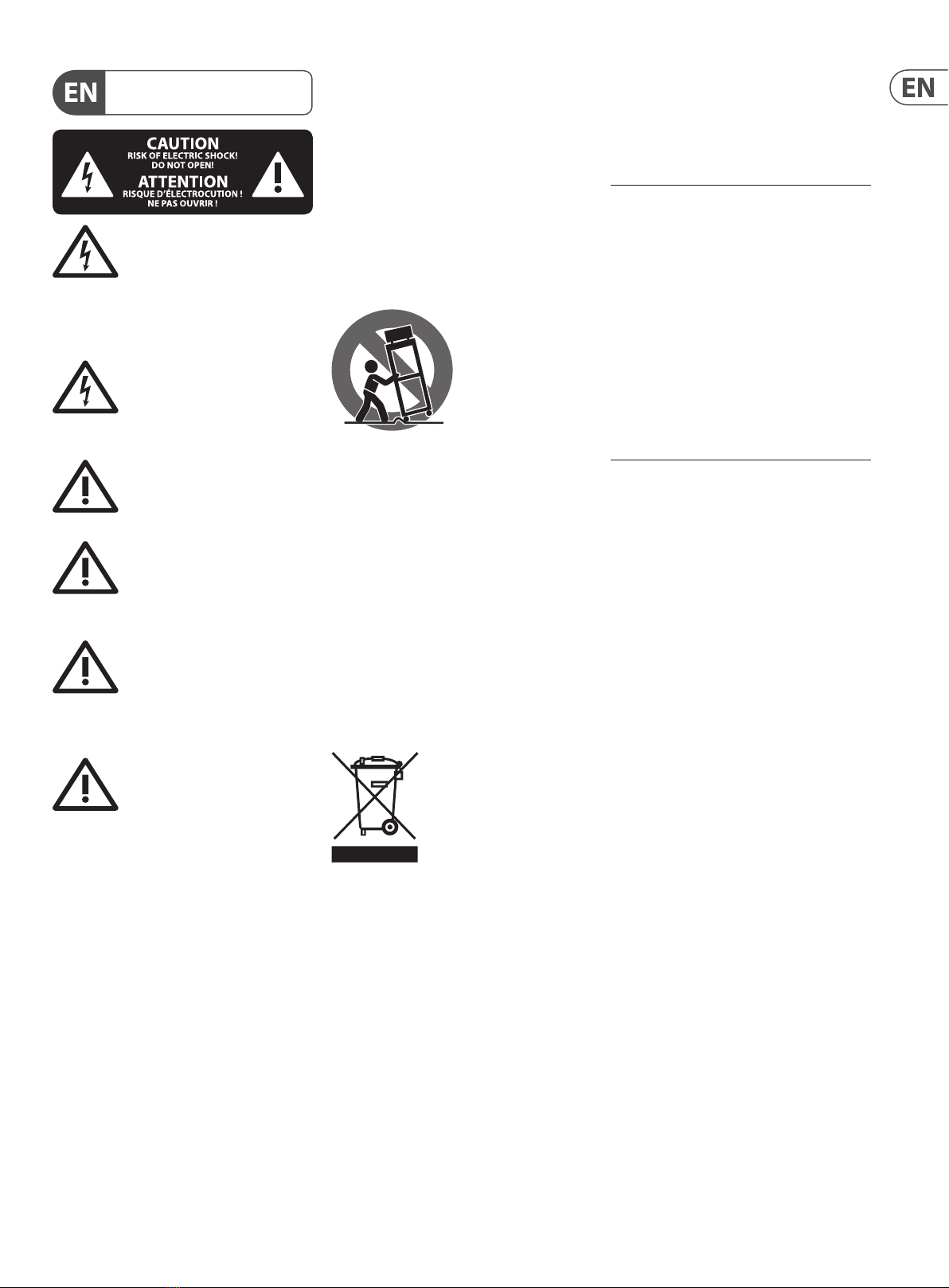
12. Use only with the
cart, stand, tripod, bracket,
or table specied by the
manufacturer, orsold with
the apparatus. When a cart
is used, use caution when
moving the cart/apparatus
combination to avoid
injury from tip-over.
13. Unplug this apparatus during lightning storms or
when unused for long periods of time.
14. Refer all servicing to qualied service personnel.
Servicing is required when the apparatus has been
damaged in any way, such as power supply cord or plug
is damaged, liquid has been spilled or objects have fallen
into the apparatus, the apparatus has been exposed
to rain or moisture, does not operate normally, or has
beendropped.
15. The apparatus shall be connected to a MAINS socket
outlet with a protective earthing connection.
16. Where the MAINS plug or an appliance coupler is
used as the disconnect device, the disconnect device shall
remain readily operable.
17. Correct disposal of this
product:This symbol indicates
that this product must not be
disposed of with household
waste, according to the WEEE
Directive (2012/19/EU) and
your national law.This product
should be taken to a collection center licensed for the
recycling of waste electrical and electronic equipment
(EEE).The mishandling of this type of waste could have
a possible negative impact on the environment and
human health due to potentially hazardous substances
that are generally associated with EEE. At the same time,
your cooperation in the correct disposal of this product
will contribute to the ecient use of natural resources.
For more information about where you can take your
waste equipment for recycling, please contact your local
city oce, or your household waste collection service.
18. Do not install in a conned space, such as a book
case or similar unit.
19. Do not place naked ame sources, such as lighted
candles, on the apparatus.
20. Please keep the environmental aspects of battery
disposal in mind. Batteries must be disposed-of at a
battery collection point.
21.
This apparatus may be used in tropical and moderate
climates up to 45°C.
Music Tribe accepts no liability for any loss which may
be suered by any person who relies either wholly or in
part upon any description, photograph, or statement
contained herein.Technical specications, appearances
and other information are subject to change without
notice. All trademarks are the property of their
respective owners. Midas, Klark Teknik, Lab Gruppen,
Lake, Tannoy, Turbosound, TC Electronic, TC Helicon,
Behringer, Bugera, Aston Microphones and Coolaudio
are trademarks or registered trademarks of Music
Tribe Global Brands Ltd. © Music Tribe Global Brands
Ltd. 2021 All rights reserved.
For the applicable warranty terms and conditions
and additional information regarding MusicTribe’s
LimitedWarranty, please see complete details online at
musictribe.com/warranty.

8HD96-24-CC-TP User Manual
HD96-24 Overview
Chapter 1. Introduction
Welcome to the HD96-24 Digital Mixing System. The HD96-24 is a transformation
of the Midas live sound experience. Designed for the modern-day live sound
engineer without compromise.
Designed from the ground up the, HD96-24 system is the rst step in a new way
of mixing and interacting with a Midas mixing console while keeping the famous
no-compromise sonic quality. New forward-thinking ideas including large touch
screen using DreamowTM control, modern multi-touch gesture control with
separate widget style areas and the Midas mCloud system to help manage many
duties of the HD96-24 system are just a few of the new concepts created to take
mixing audio to a new level.
To obtain the best results please, read this manual and enjoy the future of mixing
with the HD96-24 System.
About this Manual
The manual for the HD96-24 is designed to quickly familiarize the user with the
console layout, show how to congure and set the system up and then show how
to carry out basic functions needed to start mixing audio.
This document is aimed at professional engineers, such as front of house (FOH)
and monitor (MON) engineers, who will be using this equipment in a live sound
environment. It is assumed that the reader has previous experience of using
professional audio equipment.
This guide had been designed specically so that mix engineers and system
technicians can go straight to the areas applicable to them, that is operation,
connecting and setting up the system.
Training
The HD96-24 will continue to develop and improve over many years. It is advised
to frequently check the www.midasconsoles.com website for up to date videos,
user guides and other helpful information.
HD96-24 user documentation
To help you nd your way around the manual, it has been divided into the
following main areas:
•• Overview: This gives an overview of the HD96-24 System and contains
information about this manual.
•• Getting Started: This shows you how to set up and power up a
HD96-24 System.
•• Operation of the HD96-24 surface: This shows you how to use the
controls of the surface, navigate its GUI, route (patch) channels & busses, and
carry out various operations.
•• Description: This gives a detailed description of the HD96-24 hardware,
and the controls and their functions on both the control surface and GUI.
It provides useful reference material.
•• Appendices: This provides reference material and technical information
about the HD96-24, such as application notes, technical specications and
service information etc.
System Firmware Version
Our team of software engineers are constantly working to improve and expand
the features of the HD96-24. It is crucial to have the latest software version
installed on your system in order to achieve the best results from your system.
Updates can be found in the Midas mCloud, a new approach to track and store
system updates.
Touchscreen
The high brightness screen improves readability in outdoor situations however
the screen should not be exposed to strong direct sunlight.
Never operate the screen in strong direct sunlight. The glass and metal surfaces
of the console will become uncomfortably hot to touch. Raising internal
temperatures.
When screen brightness is set high the screen will become warm/hot depending
on ambient temperature. Reducing the screen brightness will reduce the screen
temperature.
Typically, the screen brightness will raise the temperature of the screen’s glass
surface by the following amounts:
•• Typically, at 100% brightness the screen surface is 21C above ambient.
•• Typically, at 75% brightness the screen surface is 18C above ambient.
•• Typically, at 50% brightness the screen surface is 15C above ambient.
•• Typically, at 25% brightness the screen surface is 11C above ambient.
•• Typically, at 15% brightness the screen surface is 9C above ambient.
(above is with slow fans, oce ambient typically 20C)
NOTE: A screen brightness of 15% is similar to that of an oce monitor or
standard laptop. At this brightness (15%) the screen temperature rise is 9C
The screen will be hottest at the top and bottom edges (LED locations).
Warning: The HD96-24 should not be placed or operated in direct sunlight. If the
screen is exposed to direct sunlight it may be come unresponsive and too hot to
handle. Please ensure you have suitable cover for your console.
Warranty and Registration
Midas are world renowned for quality and reliability. This product comes with the
standard Midas 10-year warranty.
Registration of your console is achieved by using the Midas mCloud, a new
concept in managing a Digital Mixing System.
Service and Support
The HD96-24 is state of the art technology. We provide incredible levels of
support and service available via the Midas mCloud or by our care team to give
owners and users condence in Midas products.
Commonly Used Terms and Denitions
Below are some of the terms used in this manual.
•• GUI – Graphical User Interface or Touchscreen.
•• Channel – Any input, Output (Aux, Flexi-Aux or Matrix).
•• Path – Any Input, Output, VCA or Master.
•• POPulation Group – A group of channels used to bring or recall paths to
the surface or screen.
•• Contributions – Any path that contributes to an output bus.
•• Touch – The action of pressing the touch screen to turn on or select
a function.
•• Select – The same as touch.
•• Pinch – Two ngers squeezed together, used to tighten or widen equaliser
width (Q).
•• Swipe – Moving a page left to right or up and down by pressing, holding
and moving in the required direction.

9HD96-24-CC-TP User Manual
•• Press and Hold – Either a way to select all the paths on a current page
for multiple editing or a way to engage a parameter function that may
be critical if press in error, for example atting the EQ is a press and hold
function.
•• Widget – The name for a window or various windows displaying
information on the GUI as part of a workow.
•• Workow – Visualizes the activities needed to mix audio.
•• Pot – A physical rotary control used to adjust a level or value.
•• Interrogation – Pressing and holding a function to see the parameters
associated with that control.
Chapter 2. HD96-24 Overview
Introducing the HD96-24 Digital
Mixing System.
For decades Midas has been a driving force in the world of pro audio. Building
on the incredible success of the XL8 and PRO Series with their exemplary audio
performance and road-proven rugged and reliable construction, the Midas PRO
Series became the gold standard in concert touring and installed live sound.
Oering the same outstanding sample-synchronised and phase-coherent audio
performance, interpolated control functions and intuitive navigation, the PRO1,
PRO2, PRO3, PRO6, PRO9 and later PRO-X Live Audio Systems have become one of
the industry’s main choices for live sound mixing.
Now the HD96-24 pushes the boundaries further yet again with a 21” touchscreen
for hands on instant access to all controls. Parameter adjustment becomes
fast and easy with gesture touch interaction using the precise and accurate
multi-touch display which allows up to 10 simultaneous touches. Featuring 144
Simultaneous inputs and 120 (96 x Flexi Aux + 24 x Matrix) time-aligned and
phase-coherent busses with no stealing of resource’s in channel or bus counts.
True and consistent 96 kHz sampling frequency and 64-bit oating-point
processing provide exemplary quality audio processing, and the oversampled
and interpolated digital signal processing algorithms, combined with the fully
interpolated and touch sensitive user controls, result in the smooth continuous
response and immediacy of working on an analogue console.
The HD96-24 features the rugged and road-proven KLARK TEKNIK HyperMAC
(HMAC) and SuperMAC (AES50-compliant) networking technologies with their
ultra-low and deterministic latencies and robust error correction. Its powerful
audio networking oers up to 624 inputs and 654 outputs at the 96kHz sample
frequency depending on conguration.
The 24 VCA (Variable Control Association) and 24 POP (POPulation) groups,
combined with the advanced touch screen navigation system, 28 faders,
assignable controls and innovative shortcut area allow simultaneous display
and control of all the critical information required to craft an unprecedented
mix experience.
Overview
The HD96-24 is a very powerful and exible audio processing system that
provides a complete solution for any audio mixing and signal distribution
application in a live sound environment. Common features of the HD96-24 Live
Audio System include:
•• Graviton Audio Engine incorporated into surface
•• 144 exi inputs
•• 120 busses.
•• Up to 96 stereo Eects
•• 96 Ultima Stereo Dynamic EQs
•• 32 Ultima Stereo Multiband Compressors
•• 24 VCA (variable control association) groups, and 24 POPulation groups
•• Variable phase per input channel
•• Input - Aux - Aux - Matrix routing (Delay compensated)
•• True 64-bit FPGA processing with GPU coprocessing
•• 5 tap o points per channel per send, all delay compensated
•• Dedicated 16 into 12 shout mixer with instant conguration recall
•• Dual Solo busses featuring duckers and AFL/PFL congurable for input
and output
•• True Audition™
•• True Preview ™
•• Channel AI™
•• 21" full colour TFT high brightness display screen with capacitive
touch sensing
•• Advanced and multi-gesture touchscreen user interface
•• Award-winning Midas microphone preampliers
•• HyperMAC and AES50 networking allows up to 576 inputs and 576 outputs
sources @ 96 kHz sample rate
•• Dual network bridge format converter with up to 128 bidirectional channels
and asynchronous sample rate conversion
•• Touring grade road case featuring marine grade plywood, aluminium
extrusions and composite density protective foam
•• Integrated Bluetooth and wireless transceiver module
•• Dual ULTRANET Ports providing 32 additional digital outputs
•• 28 Midas PRO motorised 100 mm faders
•• Fully interpolated touch sensitive controls
•• Dual redundant auto-ranging universal switch-mode power supplies
•• 10-Year Warranty Program
•• Designed and engineered in the UK
Key features
New Surface Design
DreamFlow™ UI
Full HD multitouch screen - daylight coated
40 x 18-bit colour 240x240 channel LCDs
Total congurability, anything anywhere
36 assignable rotaries
Full channel control with dedicated 4-band EQ and dynamics section
Manchino workow heralds new Era in console setup speed
Completely customisable surface
28 faders
Dante, Madi and USB interfaces available directly in surface with two CM1 slots
Graviton Audio Engine utilises two HyperMac ports which are congurable for
dual redundant or independent operation
Over 39 Eects to choose from

10 HD96-24-CC-TP User Manual
Including Eects from TC Electronic.
Tc electronic system 6000 FX (VSS4)
Tc electronic 2290 (coming soon)
Tc electronic system 3000 FX (VSS3)
KT DN780 Reverb
HD2a
HD 670
KT 1176
R-Comp 3
KT Bus compressor
Mtec EQP-HD
Mtec MEQ-HD
M6 Multiband compressor and dynamic EQ.
HD Stressor compressor
HD Wave Designer
Ultra-Dualistic, Voice Doubler
XL4 EQ
Applications
The HD96-24 is the go-to high-end Midas Digital Console System, akin to the
‘industry standard’ Heritage 3000 and XL4. Although the HD96-24 is designed for
the traditional touring live sound environment, it is also ideal for theatre, house
of worship installations and broadcast. So, being a truly multi-functional console
in the Midas tradition, the HD96-24 is suitable for many applications, such as:
•• Live sound touring Front of House (FOH) or Monitors (MONS) duties.
•• Live sound theatre FOH or MONS duties.
•• Live sound & broadcast for house of worship FOH or MONS duties.
System Components
The HD96-24 surface now brings together all DSP and processing into one place.
This allows for quicker set-up. With built in Wi-Fi and Bluetooth the HD96-24 can
talk to the mCloud for show le back-up, software updates, fault tracking and
even the location of the desk anywhere in the world.
All the I/O is handled by the familiar Midas Blue DL series rack which combines
the warmth and authenticity of analogue circuitry with the precision and agility
of state-of-the-art digital techniques. Extreme care has been taken in the
planning and execution of the PCB layout to maintain exceptional grounding and
analogue/digital separation with the highest quality of sonic performance.
Compatible DL Series units are:
DL231/431
DL251/252
DL151/152/153/154/155
The Klark Teknik DN9680 8 Port AES50 extender and multiplexer can be directly
connected to the HD96-24 which Extends AES50 connections up to 500m with
optical bre or 100 m with CAT5 cable. DN9680 supports both optical bre and
copper snakes using a Gigabit Ethernet digital audio point-to-point link. A dual-
bre Neutrik opticalCON DUO connector is used for optical bre snake connection,
enabling a bidirectional optical link on one multi-mode dual bre cable
The DN9680 acts as a bidirectional multiplexer and demultiplexer and combines
the eight incoming AES50 streams into the outgoing snake connection, and
simultaneously also takes the incoming snake connection and unbundles the
eight AES50 streams and routes them to the corresponding AES50 ports with
redundant connections available. This allows 192 bidirectional channels of audio
to be used.
System Busses
The HD96-24 has comprehensive system busses to suit demanding applications,
comprising:
1. 2 stereo solo busses, routable from all locations and allowing for dual
operator
2. 3 master busses, routable from the mic/line inputs (up to 144), and 96 aux
busses.
3. 24 matrix busses, routable from the mic/line inputs (up to 144), 96 aux
busses and three master busses.
4. 96 aux busses (either standard or exi-aux, routable from the mic/line inputs
(up to 144) or exi aux bus to aux bus for group or stem style processing.
All of the bus routings provide simultaneous and time aligned mixing of all the
sources, which will be switchable for minimum latency requirements.
For monitor mixing, the master, matrix and aux busses can all be routed directly
from the input channels, with independent level controls providing up to 123
monitor mix busses. Flexi-Aux busses allow group mixing of channels to be sent
to Auxes, Matrices or the Masters, for example, mix and process all your drums via
a Flexi-Aux then send to an IEM Aux.
For traditional FOH group mixing, any (or all) of the aux busses can change to
operate post-channel fader and pan (that is, aux gain xed at unity).

11 HD96-24-CC-TP User Manual
Mix matrix
Fundamentally, the mix matrix denes the capability of the HD96-24. Probably the best way to imagine the mix matrix is to think of an analogue console layout, where
inputs run vertically, and busses run horizontally. A mix matrix is usually dened as the number of busses and the quantity of simultaneously mixable inputs there are
per bus. The following diagrams illustrate the capability within the HD96-24 system.
Processing
Although the HD96-24 system allows for considerable insertion of external processing, it also embodies ample internal high-quality processing to eliminate the need
for this, in the interests of simplicity and reduced overall system size, weight and cost.
Processing components
The processing available is:
•• Up to 144 x 12 or 24dB/Oct. High pass lters.
•• Up to 144 x 6 or 12dB/Oct. Low pass lters.
•• Compressor/limiters on every input and output channel with side chain ltering and multiple operating “signatures”.
•• Up to 144 gates with side chain ltering.
•• 144 x 4-band parametric input EQ with multiple shelf “modes”.
•• 123 x up to 4-band parametric output EQ with HPF/LPF modes.
•• Up to 24 eects processors slots selectable from reverbs, delays, phase shifters, compressors and pitch shifters.
Input channel processing
Each of the 144 (maximum) full-function exi input channels has:
•• Analogue gain and digital trim.
•• Polarity reverse switch.
•• Input delay.
•• Swept high pass lter with choice of two lter slopes.
•• Swept low pass lter with choice of two lter slopes.

12 HD96-24-CC-TP User Manual
•• Swept all pass lter with a choice of two options of phase range with low and high optimization.
•• Frequency-conscious compressor with choice of four compression styles.
•• Frequency-conscious noise gate with external side chain.
•• Insert point. (half normalized i.e. the insert send can be used as a channel direct output, even if the insert return isn't switched in).
•• 4 Band Parametric EQ lter with various lter options.
•• Routing via level controls to 120 mix busses.
•• Routing via pan control to left and right master busses.
•• Routing to mono master bus.
•• Direct output. Choice of 3 pick-o points, with independent output level/mute.
•• 3 Slots for FX inserts
Mix channel processing
Each of the auxiliary mix busses has:
•• Group or Mix mode.
•• Dual mono or stereo pair modes. Mono, Linked or Stereo where a single fader controls 2 linked adjacent paths.
•• Up to 4-band PEQ.
•• Frequency-conscious compressor with choice of four compression styles.
•• Insert point.
•• Routing via level controls to the matrix busses.
•• Routing via pan control to the left, right and mono master busses.
•• Direct input with independent input level/mute.
Output channel processing
Each of the matrix busses has:
•• Up to 4-band PEQ.
•• Four-mode frequency-conscious compressor with soft clip limiter and external side chain.
•• Insert point.
•• Direct input.
Each of the three master output busses has:
•• Up to 4-band PEQ.
•• Four-mode frequency-conscious compressor with soft clip limiter and external side chain.
•• Insert point.
•• Direct input.
•• Routing via level controls to the matrix busses.
Audio Physical Connections
The maximum total number of physical analogue XLR connections possible on a HD96-24 is 488 plus talk line in and talkback mic in on the rear of the surface.
The maximum number of 488 congurable I/O can be increased up to 654 (488 analogue + up to 128 CM1 + 32 ULTRANET + 4 AES3) depending on the combination of
dierent types of I/O card can be used.
All of the congurable I/O are freely routable on a scene-by-scene basis.
Network
The network of the HD96-24 utilises the physical connectivity of Ethernet (EtherCon® connectors and Cat 5e/copper cable) but replaces its data protocol with AES50
protocol (implemented as SuperMac) and the HyperMac high capacity system, which are more suited to high quality, low latency audio distribution. The use of the AES
standard allows straightforward interfacing with any third-party hardware that also utilises this connection.

13 HD96-24-CC-TP User Manual
AES50 connections carry digital audio and control data bi-directionally down a single cable. Cat 5e cable is used for the ‘local’ connections and the dual digital ‘snake’
(equivalent to a 384-channel analogue multi-core, 192 channels per snake connection) between console and I/O. The combination of audio, control, clock and third-
party Ethernet data in a single network means that the hardware interfaces on a single RJ45 connection.
All system connections can be duplicated for full dual redundancy.
mCloud Network
The Midas mCloud network is a brand-new concept in le and system management. The HD96-24 has built in Wi-Fi capabilities which allow the surface to share its
information over a Wi-Fi connection and any other network connections to the mCloud. Be reassured the connection is completely safe with military grade encryption.
Great lengths have been taken to keep information secure.
The mCloud can be used to store your show les, preset les and all other types of data from the console. If you leave your USB stick with your vital settings at home,
you can directly log into your mCloud account and load your show le straight to the HD96-24 without breaking into a sweat.
New system updates can be downloaded directly to the surface ready for you to update when you’re ready. A list of all previous software versions will be stored on the
HD96-24 for peace of mind.
It also allows audio rental companies to keep a track of registrations, software versions, warranties and diagnostic logs. All the admin for running a busy hire company
in one place.
Each user of the HD96-24 will be prompted to set up a user prole which also in turn congures your mCloud account.
HD96-24 software
The operating system of the HD96-24 built on Linux, which is an open-source, stable, proven operating system (OS). Linux is used in many mission-critical applications
worldwide and has allowed Midas’ software engineers to write a ground-up system that contains no ‘hidden’ or unused code. This has resulted in an ecient, compact
application, which is quick in operation, quick booting and comparatively easy to debug.
Graphic User Interface (GUI)
The HD96-24 has a 21” touch screen that provides a quick and intuitive workow. Modern touch gestures such as pinch and smooth touch screen faders have been
included to speed up workow and let you concentrate on the mix. Not only does the GUI reect what is happening on the control surface, but it also provides extra
functionality via a top and side bar menu. These menus provide access to all the pages that you will require to set up, congure, manage and operate the entire control
surface.
Gone are the days of only one touch on a screen at a time. Use both hands to manipulate up to 10 faders at a time if you so wish.
Pinch gesture showing EQ width adjustment.
Independent widget style areas are extensively used to display various dierent types of information at once, all fully customisable to suit your workow.
System Card Expansion
The HD96-24 has 2 x CM-1 slots built in for further audio expansion. Adding up to an additional 128 channels
of I/O greatly increases networked capabilities. Virtual sound checks and recording have never been easier to
set-up and achieve with exible options. Being able to support new and emerging protocols via its two
industry-standard expansion slots give the HD96-24 a greatly extended shelf life.

14 HD96-24-CC-TP User Manual
Chapter 3. System Setup
This chapter shows you how to set up a live audio system to its standard conguration.
Initial set-up procedure
Initial system set-up basically comprises:
Unpacking and checking the equipment.
Connecting up the equipment.
Powering the equipment.
Initial patching.
Type of snake connection.
Conguring the rack unit(s).
User Prole use.
Unpacking the equipment
After carefully unpacking the equipment, save all packing materials, as they will prove useful should it become necessary to transport the equipment later. Inspect the
equipment carefully for any sign of damage incurred during transportation. It has undergone stringent quality control inspection and tests prior to packing and was
in perfect condition when it left the factory. However, if the equipment shows any signs of damage, notify the transportation company without delay. Only you, the
consignee, may institute a claim against the carrier for damage during transportation.
The screen and LCD displays are protected by a plastic lm. Carefully peel this o before use.
Warning: This can induce static that can cause temporary distortion of LCD displays. This is rectied after rebooting the console.
Ventilation
The HD96-24 has air intake vents on each side of the console. Air is drawn in through the console side vents and exits via the two fans on the rear of the surface. It is
vital none of these airways are blocked as overheating may occur if airow is restricted.

15 HD96-24-CC-TP User Manual
Racking the I/O
Please take note of the rack requirements as detailed below:
To ensure the correct installation and function of the outboard equipment, any rack has to meet the following general requirements:
Shock mounting (for non-installation environments)
The rack must provide adequate shock protection of the units it houses by incorporating appropriately-designed shock protection methods. For example, a foam-
suspended rack or a frame suspended on anti-vibration mounts.
The Midas I/O units have been designed such that their internal ventilation airow is drawn in through the front of the unit and expelled though the rear. To facilitate
this, rack design must ensure that cool air can ow freely through the rack in the same direction, that is, in through the front of the rack and out through the rear.
Situations where the air ows in a circular direction around and through a Midas I/O unit must be prevented. MIDAS recommends that racks with fully opening front
and rear doors are used.
Caution
Never combine units in the same rack that have been designed for a ventilation air ow direction other than that designed for the MIDAS units. To avoid this,
we recommend that any non-MIDAS units are housed separately.
Rack mount supports
Always secure the rear of the Midas I/O units to the rack via their rear rack mount support brackets. These brackets are tted to every Midas I/O unit and are
recommended for use in touring applications.
Handles on rack case
You must ensure that there are sucient external handles tted to the rack casing to enable the rack to be manoeuvred easily and safely, and by the number of
personnel suitable for the task. Also, these handles must be t for purpose.
Clearance at the rear of units
Ensure an adequate clearance at the rear of the units to provide sucient free space to enable the cables to achieve their minimum bend radius.
Securing the cables
We recommend that the cables at the rear of the units be tidied using lacing bars and cable ties. This should provide optimum access to the rear of the units for
connecting other cables, switching the units on/o etc., and also to give maximum visibility of the units’ LEDs for determining communication status, link status,
condition of audio etc.
Connection instructions
There are currently two ways to connect the system equipment together:
1. HD96-24 surface to a Klark Teknik DN9680 via copper (up to 100 m) or with a multi-mode (MM) bre optic snake (up to 500 m). Then Klark Teknik DN9680 to I/O
box (for example, DL231) via Cat5E (up to 100 m).
2. HD96-24 surface direct to I/O (for example, DL231) via Cat5E (up to 100 m).
It is imperative only STP Cat5E Rated cables are used!
Length = 100M Point to point as per the Cate5E ethernet protocol - Please take into consideration any in line connections or links reduce the overall
cable length.

16 HD96-24-CC-TP User Manual
AES50 Cat5e STP vs UTP cables.
Music Tribe are standardising the use of Ethercon cables used for AES50 connections and state that customers must use Shielded Twisted Pair (STP) cable only with
shielded RJ45 plugs and Ethercon shells.
STP cable has the added advantage of a foil or braided shield that guards the cable against electromagnetic interference. A good foil or braided shield and correctly
connected shielded plugs and shells also helps protect against Electrostatic discharge (ESD) that can be the cause of dropouts on AES50 connections.
Occasionally shielded Ethercon cables will leave the shield disconnected on one end to help with ground loops, even though it has no benet for AES50 connections.
These connections should have continuity of the shield on both ends including the Ethercon shells. This will ensure the best possible protection against strong ESD
impacts, such as handling discharges or even lightning strikes in the neighbourhood.
All AES/EBU connections must use good quality 110Ω AES/EBU cable to ensure correct operation.
System components
Below is a list of currently compatible system I/O components with the HD software. When I/O is connected to the HD96-24 system it will be necessary to be update to
the latest HD I/O software. The updater is built into the console and guides you through the update process. Once updated, I/O boxes will still be compatible with Pro
Series consoles.

17 HD96-24-CC-TP User Manual
Connection via HMAC to DN9680, then AES50 connection from DN9680 to DL231
Direct connection of I/O in AES50 redundant mode

18 HD96-24-CC-TP User Manual
Powering the system
Important Note:
Make sure your speaker system, in-ears or monitor wedges are muted until the start-up of the system has been completed.
After all system interconnections have been made, start up the system by doing the following:
Switching on the HD96-24
1. Plug the two mains cables into the mains power outlets. Both power supply modules should be supplying power to the HD96-24 surface for correct redundant operation.
2. Plug the connectors of the mains cables into the IEC mains sockets on the rear of the HD96-24.
3. Turn on the power to the HD96-24 surface by switching both D.C. POWER switches on. The surface will boot up. Once the default GUI screen is displayed, it is ready for use.
To switch o the HD96-24 surface
1. Make sure you have saved any shows, scenes or settings you require.
2. In the GUI, select Menu from the top bar, then press and hold the red Shutdown button at the bottom of the menu until the line traces around the outside of the
red button. The shutdown procedure will then initiate.
3. The screen will go blank, the MIDAS logo will briey be displayed, then the screen will go blank for a second time indicating the shutdown procedure has nished.
Once the system has been shut down correctly is it safe to turn o both D.C. power switches (rear of surface).
Setting up the ID of the unit(s)
After connecting up your system, you may need to set up the ID of the unit(s) in the rack, such as the DL231 I/O, DL251 I/O or DL15x I/O, as each unit within the same
family of units must have its own unique ID number.
Note: The I/O unit doesn’t have to be connected in the system for you to set up its ID, as the procedure can be carried out oine.
To set up the ID of a I/O unit
Although the programming menu of each type of I/O unit may look slightly dierent, the procedure for setting up its ID is basically very similar. For full instructions on
how to set up the ID of each particular I/O unit, refer to its operator manual.
The unit ID number is shown on the LCD screen at the end of the top row of text.
1. Press MENU and hold for approximately two seconds to enter the main menu.
2. Use the up and down arrow buttons to navigate to the set ID option.
3. Press SELECT to enter the set ID option.
4. Press MENU repeatedly to exit the main menu. (The unit will automatically exit programming mode after 20 seconds of inactivity).

19 HD96-24-CC-TP User Manual
I/O Box Update
Note: I/O boxes will need to be updated in order to work with the HD96-24 system. The I/O Box and Device updater can page be found in the Update Manager
(side bar menu). With all your I/O connected with the console as master clock, press Sync I/O and follow the instructions. Updated I/O boxes will still work and are fully
compatible with Pro Series consoles.
1. Press Sync I/O. Any I/O racks will appear after the I/O scan.
2. FOH I/O connections will be displayed in this section.
3. HMAC I/O connections will be displayed in this section.
4. Each device will display its family type (DL15x, DL231), its current software version and the ID number for the I/O device.
5. Select all currently Sync’d I/O devices ready for update. If you prefer individual racks can be updated.
6. Pressing Update Selected updates all selected I/O to the latest version of HD software.
Connection to the internet
The Hd96-24 has a built in Wi-Fi router and Ethernet port to allow a connection to the internet.
Wired connection:
A DHCP server enables the HD96-24 to request IP addresses and networking parameters automatically from the Internet service provider (ISP), reducing the need for
a user to manually assign IP addresses to all network devices. Plugging the Ethernet port into a cat5 socket/port at your venue with an active internet connection will
automatically connect you to the internet for updates and mCloud use.
WiFi connection:
Local WLAN networks will allow you to connect to them with the correct password. Follow the on screen instructions to connect.
Note: An active internet connection is required to use mCloud network and for mCloud system updates. Updates and update instructions can also be downloaded
from the https://cloud.midasconsoles.com website.

20 HD96-24-CC-TP User Manual
Hardware Connections
Other manuals for HD96-24-CC-TP
2
Table of contents
Other Midas Dj Equipment manuals