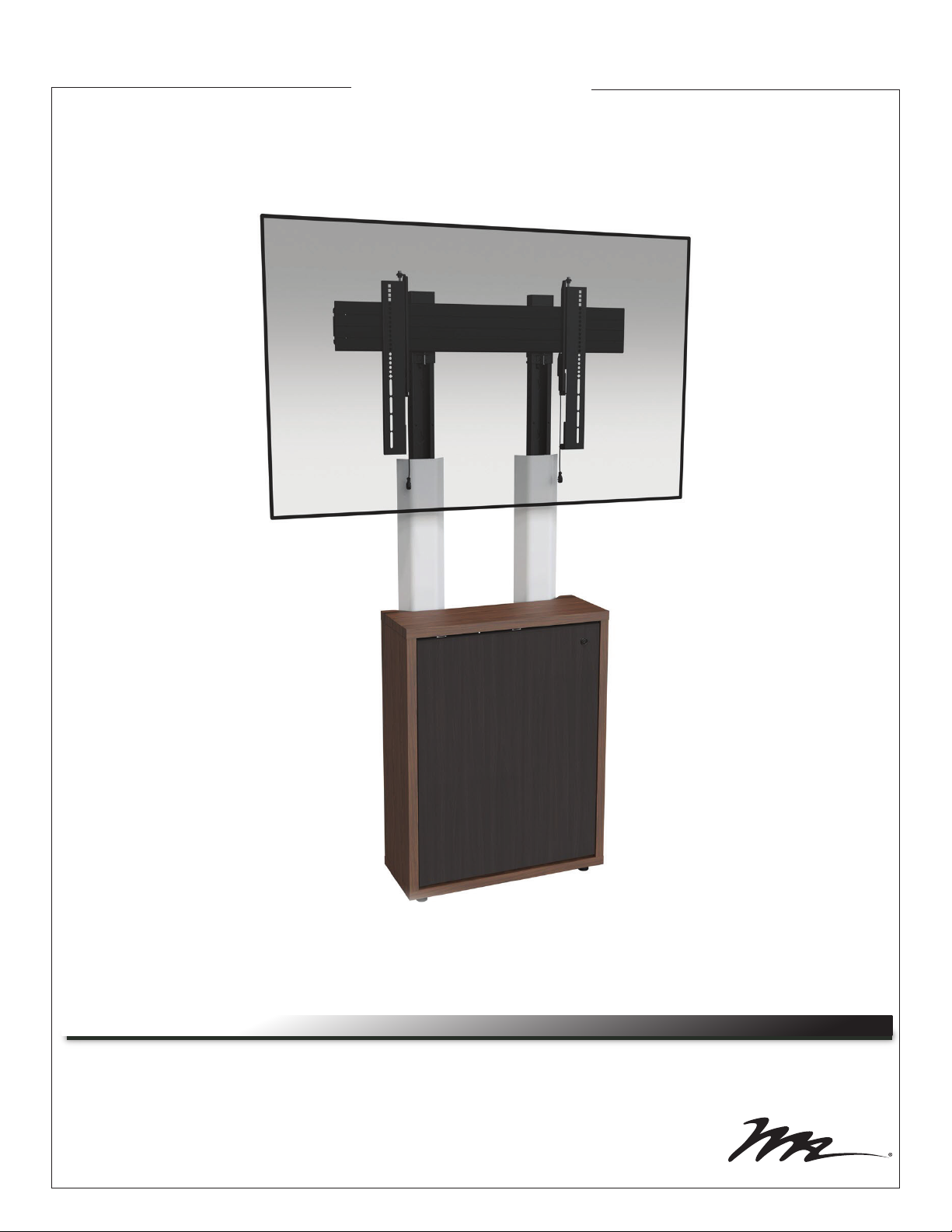
Middle Atlantic WoodKit C3 Series User manual

Thank you for purchasing a C3 Series Display Mount option. Please read these instructions
thoroughly before installing or assembling this product.
C3 Series
THANK YOU
Instruction Sheet
Display Mount Option (C3-XX-LDXU)
NOTE: A 1-Bay C3 credenza with a display mount option (C3-XX-LDXU)
configured for a single displays (display not included) shown.
100-00034 Rev A

Page 2
IMPORTANT SAFETY INSTRUCTIONS
DANGER HAZARDOUS VOLTAGE: The lightning flash with the arrowhead symbol, within an equilateral triangle is intended to alert the user to the
presence of uninsulated dangerous voltage within the product’s enclosure that may be of sufficient magnitude to constitute a risk of electric shock to
persons.
WARNING: A warning alerts you to a situation that could result in serious personal injury or death.
CAUTION: A caution alerts you to a situation that may result in minor personal injury or damage to the product and/or property.
NOTE: A note is used to highlight procedures pertaining to the installation, operation, or maintenance of the product.
• Read these instructions.
• Keep these instructions.
• Heed all warnings.
• Follow all instructions.
• Clean only with dry cloth.
• Only use attachments/accessories specified by the manufacturer.
WARNING: Failure to read, understand and follow the following information can result in serious personal injury, damage to the
equipment or voiding of the warranty. It is the responsibility of the Installer/User to ensure that this product is loaded according to
specifications.
WARNING: Exceeding the weight ratings on page 4 can result in serious injury or damage to the equipment. It is the responsibility of
the Installer/User to ensure the components installed do not surpass the weight ratings as an unstable condition can occur which may
cause possible injury or damage.
CAUTION: Note that during construction, there must be no possibility of personal injury, for example the squeezing of fingers or
arms.
CAUTION: If there is visible damage on the product, it must not be installed.
CAUTION: Safety measures must be practiced at all times during the assembly of this product. Use proper safety equipment and
tools for the assembly procedure to prevent personal injury.
CAUTION: For loading, always put heavier items at the bottom of the bays, not near the top, in order to help prevent the possibility
of the furnishing tipping over.
CAUTION: The appliance is not intended for use by young children or infirm persons without supervision.
Safety Instructions: Rack Mount
Elevated Operating Ambient: If installed in a closed or multi-unit rack assembly, the operating ambient temperature of the rack
environment may be greater than room ambient. Therefore, consideration should be given to installing the equipment in an environment
compatible with the maximum ambient temperature (Tma) specified by the manufacturer.
Reduced Air Flow: Installation of the equipment in a rack should be such that the amount of air flow required for safe operation of the
equipment is not compromised.
Mechanical Loading: Mounting of the equipment in the rack should be such that a hazardous condition is not achieved due to uneven
mechanical loading.
Circuit Overloading: Consideration should be given to the connection of the equipment to the supply circuit and the effect that
overloading of the circuit might have on overcurrent protection and supply wiring. Appropriate consideration of equipment nameplate
ratings should be used when addressing this concern.
Reliable Earthing: Reliable earthing of rack-mounting equipment should be maintained. Particular attention should be given to supply
connections other than direct connections to the branch circuit (e.g. use of power strips).
Disconnect Device (Pluggable Equipment): The socket-outlet shall be installed near the equipment and shall be easily accessible.
WARNING: Middle Atlantic Products, electrical systems conform to and should be properly grounded in compliance with require-
ments of the current National Electrical Code or codes administered by local authorities. All electrical products may present a possible
shock or fire hazard if improperly installed or used. Electrical products may bear the mark of a Nationally Recognized Testing
Laboratory (NRTL) and should be installed in conformance with current local and/or the National Electrical Code.

Page 3
DANGER TENSION DANGEREUSE: Le symbole de la pointe de flèche, dans un triangle équilatéral, est destiné à alerter l'utilisateur sur la
présence de tension dangereuse non isolée dans l'enceinte du produit qui peut être d'une ampleur suffisante pour constituer un risque d'électrocu-
tion.
AVERTISSEMENT: Un avertissement vous avertit d'une situation pouvant entraîner des blessures graves ou la mort.
ATTENTION: Une attention vous avertit d'une situation pouvant entraîner des blessures mineures ou des dommages au produit et/ou à la
REMARQUE: Une remarque est utilisée pour mettre en évidence les procédures relatives à l'installation, au fonctionnement ou à l'entretien du
produit.
INSTRUCTIONS IMPORTANTES SUR LA SÉCURITÉ
• Lire ces instructions.
• Conservez ces instructions.
• Respectez tous les avertissements.
• Suivez toutes les instructions.
• Nettoyer uniquement avec un chiffon sec.
• N'utilisez que des accessoires spécifiés par le fabricant.
AVERTISSEMENT: Le dépassement des notes de poids à la page 4 peut entraîner des blessures graves ou des dommages à
l'équipement. C'est l'responsabilité de l'installateur/utilisateur de s'assurer que les composants installé ne dépassent pas les notes
de poids comme un instable condition peut se produire qui peut causer des blessures ou dommages.
ATTENTION: S'il ya des dommages visibles sur le produit, il ne doit pas être installé.
ATTENTION: Des mesures de sécurité doivent être mises en œuvre en tout temps lors de l'assemblage de ce produit. Utiliser un
équipement et des outils de sécurité appropriés pour la procédures de afin d'éviter les blessures.
ATTENTION: Notez que pendant la construction, il ne doit pas y avoir de risque de blessure, comme par exemple le écraser des
doigts ou des bras.
ATTENTION: Pour le chargement, placez toujours des articles plus lourds au bas des baies, pas près du sommet, afin d'éviter la
possibilité de basculement de l'ameublement.
ATTENTION: L'appareil n'est pas destiné à être utilisé par des enfants en bas âge ou des personnes infirmes sans surveillance.
AVERTISSEMENT: Refus de lire, comprendre et suivre la renseignements suivants peut traduire par de graves blessures, des
dommages à l'équipement ou invalider la garantie. Il est la responsabilité de l'installateur/utilisateur de s'assurer que ce produit
est chargé conformément aux spécifications.
Consignes de sécurité: montage en rack
Température de fonctionnement élevée: Si installé dans un rack fermé ou à unités multiples , la température ambiante de fonctionne-
ment de l'environnement du rack peut être supérieure à ambiante de la pièce. Par conséquent, il faudrait envisager d'installer l'équipe-
ment dans un environnement compatible avec la température ambiante maximale (Tma) spécifiée par le constructeur.
Réduction Air accréditives: Installation de l'équipement dans un rack doit être telle que la quantité de flux d'air nécessaire au bon
fonctionnement de l'équipement ne soit pas compromise.
Chargement mécanique: Le montage de l'équipement dans le rack doit être telle qu'une condition dangereuse ne lié à un chargement
mécanique irrégulier.
Surcharge des circuits: Il faudrait envisager à la connexion de l'équipement au circuit d'alimentation et l' effet que la surcharge du
circuit pourrait avoir sur la protection contre les surintensités et le câblage d'alimentation. Examen approprié des équipements évalua-
tions de la plaque signalétique doit être utilisée pour traiter de cette préoccupation.
Mise à la terre fiable: Fiable mise à la terre de l'équipement de montage en rack doit être maintenue. Une attention particulière devrait
être accordée aux connexions d'alimentation autres que les connexions directes vers le circuit de dérivation (par exemple de l'utilisation
de bandes de puissance).
Appareil Disconnect (Équipement Pluggable): La prise de courant doit être installée à proximité du matériel et doit être facilement
accessible.
AVERTISSEMENT: Les produits Middle Atlantic, les systèmes électriques sont conformes et doivent être correctement mis à la
terre conformément aux exigences du Code national de l'électricité en vigueur ou aux codes administrés par les autorités locales.
Tous les produits électriques peuvent présenter un risque d'électrocution ou d'incendie s'ils sont mal installés ou utilisés. Les
produits électriques peuvent porter la marque d'un laboratoire d'essais reconnu au niveau national (NRTL) et doivent être installés
conformément au code électrique local et/ou national en vigueur.

Page 4
WEIGHT RATINGS
AVERTISSEMENT: Ce produit est destiné à être utilisé uniquement avec les produits et les poids maximum indiqués. L'utilisation
avec d'autres produits ou produits plus lourds que le poids maximum indiqué peut entraîner une instabilité pouvant causer des
blessures. Le poids total de l'équipement ne doit pas dépasser les quantités indiquées dans le tableau précédent.
WARNING: This product is intended for use only with the products and maximum weights indicated. Use with other products or
products heavier than the maximum weights indicated may result in instability causing possible injury. Total equipment weight must
not exceed the amounts indicated on the previous table.
C3 1-Bay 24” (610 mm) and 32” (813 mm) Height
C3 2-Bay 24” (610 mm) and 32” (813 mm) Height
C3 3-Bay 24” (610 mm) and 32” (813 mm) Height
C3 4-Bay 24” (610 mm) and 32” (813 mm) Height
Slide-Out Rack Option (C3-TECHKIT4-SO)
Fixed Rack Option (C3-TECHKIT4-ST)
Shelf Kit Option (C3-SHELFKIT, Weight Per Shelf)
Display Mount Option (C3-XX-LDXU, Weight Per Screen)
75 lbs. (34 kg) Per Bay, 25 lbs. (11 kg) On Top, 100 lbs. (45 kg) Maximum Total Rated Load
75 lbs. (34 kg) Per Bay, 50 lbs. (23 kg) On Top, 200 lbs. (91 kg) Maximum Total Rated Load
75 lbs. (34 kg) Per Bay, 75 lbs. (34 kg) On Top, 300 lbs. (136 kg) Maximum Total Rated Load
75 lbs. (34 kg) Per Bay, 100 lbs. (45 kg) On Top, 400 lbs. (181 kg) Maximum Total Rated Load
75 lbs. (34 kg) Maximum Total Rated Load
30 lbs. (14 kg) Maximum Total Rated Load
125 lbs. (57 kg) Maximum Total Rated Load
Model Number Weight Rating
SUPPLIED COMPONENTS AND HARDWARE
(4x)
¼”-20 x 2½” Bolt
E
(4x)
¼”-20 x 3/8”
Phillips Thread Forming Screw
B
(4x)
10-32
Flange Nut
D
(5x)
SNAPTOGGLE® Anchor
C
TOGGLER®
(4x)
¼” Washer
F
Horizontal Extrusion
G
Dual
Single
Single or Dual Display Width
36" (914 mm)
96" (2,438 mm)
Upright Pair
A
Extrusion End Cap Pair
H
(4x)
¼”-20 x ½”
Pan Head Phillips Thread
Tapping End Cap Screws
J

Page 5
(8x)
Spacer
IH-N
(4x)
Washer
IH-P
INTERFACE HARDWARE (700-00266)
NOTE:
• To order more hardware, contact support at 1-800-266-7225.
• Additional hardware is included that may not be required for your installation.
(4x)
M4 x 12mm
Pan Head Screw
IH-A
(4x)
M4 x 20mm
Pan Head Screw
IH-B
(4x)
M4 x 25mm
Pan Head Screw
IH-C
(4x)
M5 x 12mm
Pan Head Screw
IH-D
(4x)
M5 x 20mm
Pan Head Screw
IH-E
(4x)
M5 x 25mm
Pan Head Screw
IH-F
(4x)
M6 x 12mm
Pan Head Screw
IH-G
(4x)
M6 x 20mm
Pan Head Screw
IH-H
(4x)
M6 x 25mm
Pan Head Screw
IH-J
(4x)
M8 x 12mm
Pan Head Screw
IH-K
(4x)
M8 x 20mm
Pan Head Screw
IH-L
(4x)
M8 x 30mm
Pan Head Screw
IH-M
SUPPLIED COMPONENTS AND HARDWARE (CONTINUED)
NOTE: Two sets of the following interface hardware (700-00266) are provided for dual display installations.
(2x)
5/16”-18 Flange Nut
M
C3-32-LD1U
C3-24-LD1U
C3-32-LD2U
C3-24-LD2U
Model Number Qty.
2
2
4
4
(4x)
5/16” x 3½”
Square Single Wire
Snap Pin
K
(2x)
5/16”-18 x ½” Flush
Head Self-Clinching Stud
L
C3-32-LD1U
C3-24-LD1U
C3-32-LD2U
C3-24-LD2U
Model Number Qty.
2
2
4
4
C3-32-LD1U
C3-24-LD1U
C3-32-LD2U
C3-24-LD2U
Model Number Qty.(Number of Pairs)
2
2
4
4
Interface
Standoff Bracket
N
32” (813 mm)
24” (610 mm)
Frame Height Cover Height
26.5” (673 mm)
18.5” (470 mm)
Upright Cover Pair
R
Interface Pair
P
Dual (C3-24-LD2U and C3-32-LD2U)
Single (C3-24-LD1U and C3-32-LD1U)
Single or Dual Display Qty.(Number of Pairs)
1 Pair
2 Pairs

Page 6
INTRODUCTION
NOTE:
• Only use this instruction sheet to install your C3 Series Display Mount option after you refer to the
C3 Series Credenza Frame instruction sheet (100-00032) and secure your frame to the wall using the
default (frame feet) installation height.
• Do not use the display mount option (C3-XX-LDXU) if your installation requires the credenza mounted
at a specific height and you cannot use the default (frame feet) installation height.
• If your installation includes a purchased fan kit and/or a large cover option (for your display option), after
installing this and the other options you may have purchased for your credenza, refer to the C3
Series WoodKit instruction sheet (100-00040) to install your woodkit, and then refer to the C3 Series
Fan Kit (C3-FANKIT) instruction sheet (100-00039) and/or C3 Series Display Mount Large Cover
Option instruction sheet (100-00035) to install your fan kit and/or your large cover option, respectively.
Kits and options other than the fan kit and large cover option should be installed before your woodkit
is attached to the frame
• Attaching display(s) (display(s) not included) to the horizontal extrusion must be done as the final
part of your C3 installation process. For more information, see "Attaching Display(s) to the Horizontal
Extrusion" on page 11.
• Instruction sheets may also be accessed at www.middleatlantic.com.
REQUIRED TOOLS
• Protective Eyewear
• Level
• #2 Phillips
Screwdriver
• Power Driver
• ⅜” Socket
• #2 Phillips Bit
• ½” Wrench
WARNING: Use tools with caution and follow all
necessary safety protocols.
AVERTISSEMENT: Utiliser des outils avec prudence
et suivre tous les protocoles de sécurité nécessaires.
SETTING MACRO DISPLAY HEIGHT ON YOUR UPRIGHT PAIR
NOTE:
• Each upright includes the following pieces: pre-assembled lower portions comprised of inner posts
and outer sleeves, and horizontal mounts at the tops as shown. (FIGURE A)
Upright Pair Pre-assembled Lower Portions Upright Pair Horizontal Mounts
FIGURE A
Inner Posts Outer Sleeves

SETTING MACRO DISPLAY HEIGHT ON YOUR UPRIGHT PAIR (CONTINUED)
NOTE: Large Cover option (C3-XX-XCVR-BK) does
not fit from 51” (1295 mm) to 53” (1346 mm).
A
B
C
D
51” (1295 mm) to 57” (1447 mm)
57” (1447 mm) to 63” (1600 mm)
63” (1600 mm) to 69” (1752 mm)
69” (1752 mm) to 75” (1905 mm)
Macro Display Label Height Range of Upright Pair
• Refer to the information provided with your
display(s) to get an accurate display height
measurement as shown. (FIGURE C)
• Take your accurate display height
measurement along with your C3 height
(either 32” (813 mm) or 24” (610 mm)) and
make sure your selected macro display
height interval provides adequate display
clearance after reviewing the specific 6”
(152 mm) upright pair height range on the
table provided.
C3
Height
Display
Clearance
FIGURE C
Macro
Display
Height
Measurement
Display
Height
Page 7
NOTE:
• A 4-Bay C3 credenza with a display mount option
(C3-XX-LDXU) configured for dual displays (displays not
included) shown.
• Although not installed yet in the overall procedure, the
woodkit is shown on the frame for an accurate credenza
height, display clearance, and provide a general
idea of the look your display mount provides.
2. Slide the inner post through the outer sleeve on one of
the uprights until your desired macro height letter shows
through the square opening (the same letter for each
upright) on the outer sleeve as shown. (FIGURE D)
3. Use a #2 Phillips screwdriver and a ¼”-20 x 3/8” thread
forming screw (B) to secure each upright to your selected
macro height letter.
FIGURE D
Slide until desired macro height letter shows through
square opening on the outer sleeve (same letter on
each upright) and secure with screw.
B
• There are 4 macro display height
intervals labeled A, B, C, and D,
along the inner post of each upright.
(FIGURE B)
• Each macro display height interval is
spaced 6” (152 mm) apart.
1. Start determining which macro display
height interval (A, B, C, or D) you
should use in order to properly
accommodate your display(s) by
carefully considering measurements
described on the next page. FIGURE B
BC
A
Inner
Posts
Outer
Sleeves
D

Page 8
ATTACHING UPRIGHT PAIR TO THE FRAME AND YOUR WALL
NOTE:
• Each upright is attached to specific frame locations based on single or dual display installation.
• All models support single display installation.
• Only 3- and 4-Bay models support dual display installation.
1. Use the following figure to determine where to attach each upright to your frame for single or dual
display installation. (FIGURE E)
15”
(381 mm)
15”
(381 mm)
15”
(381 mm)
15”
(381 mm)
Upright Pair Installation for Single Display
(All Models)
FIGURE E
38”
(965 mm)
38”
(965 mm)
Upright Pair Installation for Dual Displays
(3- and 4-Bay Models Only)
2. Insert the studs on the bottom (inner post) on both of the macro height secured uprights into the
holes on the top of the frame and place them against your wall.

FIGURE G
NOTE:
• If you are not securing uprights using the provided SNAPTOGGLE anchors (preferred), and
instead are going into wood studs or a solid concrete wall, you must provide your own lag bolt
hardware.
• For more information, refer to “Attaching Your Frame Using the Default (Frame Feet) Installation
Height” on page 6 in the C3 Series Credenza Frame instruction sheet (100-00032).
ATTACHING UPRIGHT PAIR TO THE FRAME AND YOUR WALL (CONTINUED)
7. Insert the studs on the bottom (inner post) on one of the macro
height secured uprights into the holes on the top of the frame as
shown. (FIGURE G)
NOTE: Verify the torque on your power driver is on the lightest setting
and only increase as necessary.
8. Use power driver, ⅜” socket and (2x) 10-32 flange nuts (D) to
attach the upright to the frame.
9. Repeat the previous steps to attach the other upright.
10. Use power driver, Phillips bit, ¼”-20 x 2½” bolts (E),
and ¼” washers (F) to secure uprights to your wall.
Do not overtighten.
3. Use a pencil and mark your wall inside the top slots of the 4 upper keyholes
on the uprights (A) as shown. (FIGURE F)
4. Remove the uprights from your frame and wall.
NOTE: Adjust torque on power driver to the “drill” setting.
5. Use power driver and ½” drill bit to drill holes in all marked locations
on your wall.
6. Insert SNAPTOGGLE®anchors (C) into holes by holding metal channels
flat alongside plastic straps and sliding channels through holes.
NOTE:
• Refer to “Attaching Your Frame Using the Default (Frame Feet)
Installation Height” on page 6 in the C3 Series Credenza Frame
instruction sheet (100-00032) to revisit instructions on how properly
use SNAPTOGGLE anchors in your type of wall.
• If you are not securing uprights using the provided SNAPTOGGLE
anchors (preferred), and instead are going into wood studs or a solid
concrete wall, you must provide your own lag bolt hardware.
Page 9
Mark inside the top slots of the 4 upper
keyholes for drill locations.
NOTE: A 1-Bay C3 credenza with
display mount option (C3-XX-LDXU)
configured for a single display
(displays not included) shown.
Top of
C3
Frame
A
Studs
WARNING: All four upper keyholes specified in these instructions are the minimum anchor points
required when securing the uprights to the wall.
AVERTISSEMENT: Les quatre trous de serrure supérieurs spécifiés dans ces instructions sont
les points d'ancrage minimum requis lors de la fixation des poteaux verticaux au mur.
FIGURE F
A
D

Page 10
ATTACHING HORIZONTAL EXTRUSION AND MAKING MICRO ADJUSTMENTS
1. Slide the interlock tabs on the upright pair horizontal mounts (positioned with the set screws on the
bottom) into the two channels on the back of the horizontal extrusion (G) as shown. (FIGURE H)
NOTE: Verify the torque on your power
driver is on the lightest setting and only
increase as necessary.
2. Use power driver, #2 Phillips bit, extrusion
end caps (H) and (4x) ¼”-20 x ½” end
cap screws (J) to attach an end cap on
each side of the horizontal extrusion.
4. Center the horizontal extrusion with your credenza and then use a #2 Phillips screwdriver to tighten
the screw on the bottom of each horizontal mount to fix it in place.
5. Carefully attach the covers (R) to the front of your uprights.
FOR DUAL DISPLAY CONFIGURATIONS ONLY: If you purchased a C3 Series Display Mount Large
Cover Option (C3-XX-XCVR-BK) for your dual display configuration, refer to the instruction sheet
(100-00035) and use the option instead.
• Each micro display height interval is spaced 1” (25 mm) apart.
3. While carefully lifting the extrusion and placing the horizontal mounts over the upright pair, use the
notch openings on the bottom of the mounts to select your micro display height interval (the same
number for each horizontal mount) and secure each one with a single wire snap pin (K) through the
holes right above. (FIGURE J)
NOTE:
• There are 7 micro display height intervals
labeled 1, 2, 3, 4, 5, 6, and 7 on the top of
the pre-assembled lower portion of your
upright pair.
FIGURE J
NOTE: Horizontal extrusion (G)
removed for clarity.
Micro display height intervals
labeled 1 - 7 along the outer
sleeve of each upright.
Secure micro display
height setting with single
wire snap pins (K) through
horizontal bracket holes
and uprights.
Slide horizontal brackets along sleeves until desired
micro height number shows through notch openings
(same number for both uprights).
Horizontal mounts positioned with
the set screws on the bottom.
FIGURE H
G

Page 11
NOTE: This topic must be done as the final part of your C3 installation process. Meaning, if you have
not yet installed any other C3 Series options you may have purchased for your credenza, your woodkit,
fan kit (if purchased), and large cover option (if purchased), you must first complete those steps (in that
order) before returning to this topic and attaching your display(s) (display(s) not included) to the hori-
zontal extrusion.
1. Use ½” wrench, 5/16”-18 x ½” studs (L), and flange nuts (M) to attach interface standoff brackets (N)
ATTACHING DISPLAY(S) TO THE HORIZONTAL EXTRUSION
2. Select from the appropriate size and length pan
head screws from the interface hardware (IH-A)
through (IH-M) for use with your display.
NOTE:
• Make sure the selected pan head screw length
does not bottom out in the mounting hole on your
display, or damage may occur. (FIGURE L)
• If you feel any resistance, stop immediately and try
either a shorter screw or use spacers (IH-N) to take
up slack.
• Verify the torque on your power driver is on the
lightest setting and only increase as necessary.
IH-P
Display Display
Display Display
IH-P
IH-P
IH-P
IH-N
IH-N
FIGURE L
FIGURE K
L
M
P
N
P
N

Page 12
ATTACHING YOUR DISPLAY TO THE HORIZONTAL EXTRUSION (CONTINUED)
3. Use power driver, Phillips bit, (4x) interface pan head screws (IH-A) through (IH-M), spacers (IH-N),
and washers (IH-P) to attach the interface pair to the back of your display as shown. (FIGURE M)
IH-P
IH-N
TIP: Use the magnets on each ring to stow the cords out of view behind your display.
NOTE: Remove your display by pulling down on the cords to open the interfaces, and then bringing the
bottom forward from the horizontal extrusion while lifting up and away from the wall.
4. Carefully team lift your
display and hook the
upper part of both
interfaces (P) over the top
of the horizontal extrusion
(G).
5. Carefully push on the
bottom of your display
until the lower part of both
interfaces click into
place over the bottom of
the horizontal extrusion.
IH-P
Location where spacer (IH-N)
is used, if necessary.
NOTE: Back of display
shown (display not included).
FIGURE M
N
Cords for
opening
interfaces.
P
IH-A through
IH-M
P

WARRANTY
For warranty information, refer to http://www.middleatlantic.com/company/about-us.aspx#warranty
Corporate Headquarters
Voice: 973-839-1011 - Fax: 973-839-1976 - International Voice: +1 973-839-8821 -
Middle Atlantic Canada
Voice: 613-836-2501 - Fax: 613-836-2690 - ca.middleatlantic.com -
Middle Atlantic EMEA Technical Support
Factory Distribution
United States: New Jersey, California, Illinois - Canada: Ontario - The Netherlands: Weert
At Middle Atlantic Products we are always listening. Your comments are welcome.
Middle Atlantic Products is an ISO 9001 and ISO 14001 Registered Company.
UNDERSTANDING NEXT STEPS
If your installation includes a purchased fan kit and/or a large cover option (for your purchased display
option), after installing this and any other options you may have purchased for your credenza, refer to
the C3 Series WoodKit instruction sheet (100-00040) to install your woodkit, and then refer to the C3
Series Fan Kit (C3-FANKIT) instruction sheet (100-00039) and/or C3 Series Display Mount Large
Cover Option instruction sheet (100-00035) to install your fan kit and/or your large cover option,
respectively.
NOTE:
• Kits and options other than the fan kit and large cover option should be installed before your woodkit
is attached to the frame.
• Attaching your display(s) (display(s) not included) to the horizontal extrusion of the display mount
option (C3-XX-LDXU, if purchased) must be done as the final part of your C3 installation process.
For more information, refer to "Attaching Your Display to the Horizontal Extrusion" on page 11.
Page 13

Other manuals for WoodKit C3 Series
4
This manual suits for next models
5
Table of contents