Last update: 2018/12/18 09:35 seqv4plus_le_mec http://www.midibox.org/dokuwiki/doku.php?id=seqv4plus_le_mec
http://www.midibox.org/dokuwiki/ Printed on 2018/12/21 23:47
Stating the obvious: the LED legs should be pointing up!
Using a screwdriver or other tool, bend the LED legs down, first against the body then so the leg
runs flat against the pad.
You may wish to leave the cathode pins unbent for now, as these should either be soldered
carefully so the switch can still go in or simply left until it is time to install the switches.
Probably bend all of the LEDs first before soldering any.
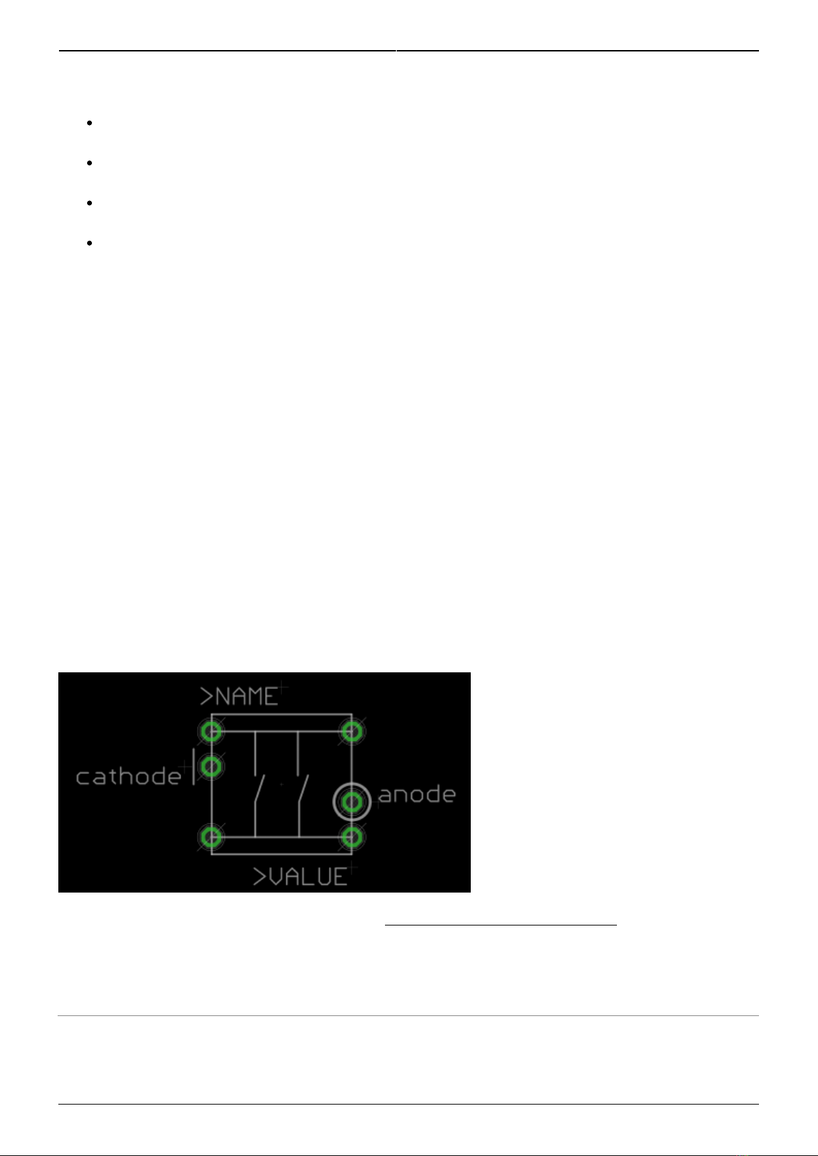
Solder at least the three anode pins, again making sure that no LED protrudes through to the
front side of the board and that the cathodes are in the correct positions.
Transistors
Transistors T9-16 (BC808 PNP) are soldered on the top side of the board. When the whole thing
is assembled, these will not be accessible, so it's important to do them right.
Don't mix them up with the BC818 NPN transistors!
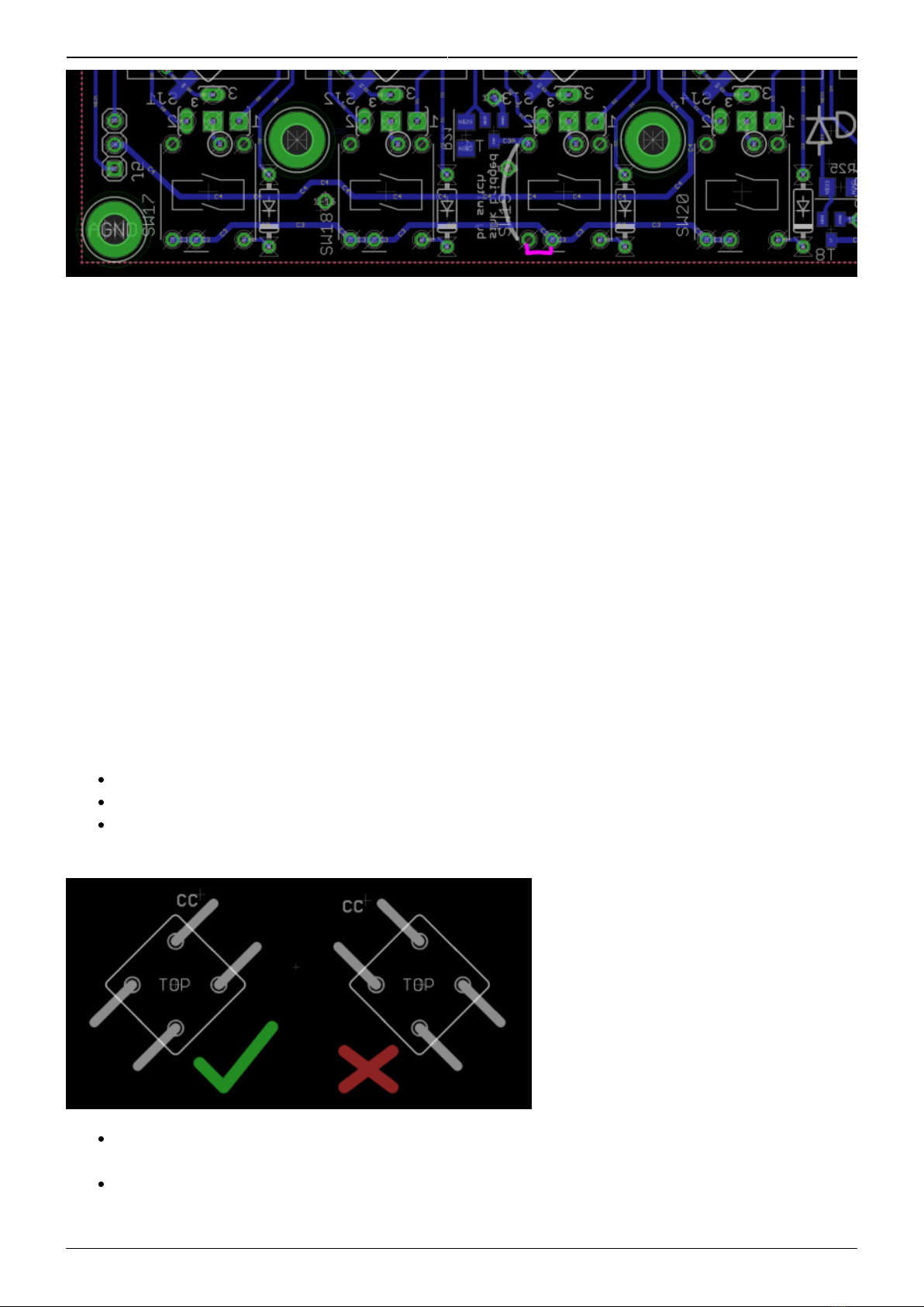
Transistors mount square on. Don't try to mount at a funny angle!
Bottom-side components
SMT resistors
Now you can use the BC818s! Note they are distributed across the board.
Resistors R18-25 adjacent to the transistors can be omitted
ICs1-5. Note that the 595s point in a different direction to the 165s!
Diodes, apart from the one next to C6, which is omitted. Ensure the legs won't interfere with the
Matias switches.
THT resistors R1-16
take special care with R2, R3, R13 and R14 that the legs are as short as possible (even
top-solder them). The encoder legs from the PCB stacked above will come down here.
resistor networks. It's very important to have the pin 1 dot aligned with the silkscreen marking.
RJs
The LEDs are available in RGB, but the official MIDIbox SEQ software only supports two of these
colours. (if wanted, you could attach 0.1“ headers to the PCB and drive the LEDs with custom
hardware.) So we need to select what LEDs are in the matrix using the resistor jumpers (RJ). Find
RJ1-8 spanning across the middle of the board. Pins A(1-8) and B(1-8) represent the 8 anode busses
and pins 1, 2 and 3 represent the pins of the LEDs in the row.
For the ELV-sourced LEDs, pin 1 as marked on the PCB is the red LED and pin 2 is the green
one. You can mix the LED colours, e.g. if you wanted to show step 1 (and 9) as a different
colour.
For the Mouser-sourced LEDs, the pinout is different. You can always check the colours of LEDs
by using the diode tester of your multimeter.
Say we want red and green LEDs throughout. Simply solder RJ1-8 with 47R from A to 1 and B to
2 for each instance. RJ9 should match RJ1. For blue and green, solder A to 2 and B to 3
(depending on the LED used).
Pinheader J4 is a vestigial connector and could be used for two extra LED functions.
RJ9 connects to the Beat LED and so 100-220R resistors should be used here.