Doug Fleenor Design NODE2 User manual

Page 1 of 10
Two Port Ethernet to DMX512 Interface
Configuration & Owner’s Manual
model: NODE2
Doug Fleenor Design, Inc.
396 Corbett Canyon Road
Arroyo Grande, CA 93420
(805) 481-9599 Voice and FAX
Manual Revision
October 2020

Page 2 of 10
Product description
NODE2 is an Ethernet to DMX512 bridging device. It accepts Streaming ACN (ANSI E1.31),
Artistic License's Art-Net and other protocols including draft sACN, KiNeT (ColorKinetics) and
ShowNet (Strand Lighting). There are two fully isolated DMX512 ports. NODE2 may be ordered
with two inputs, one input and one output, or two outputs.
Each DMX512 port has a two-digit LED display and up/down buttons to select the universe
number for the associated port. The decimal point LED on each display is the DMX512 signal
present indicator.
History. NODE2 was developed for a large hotel's ballroom and conference center. The events
department wanted a DMX512 distribution system that would allow them to plug a console into
any of the venue's input wall plates, and route that signal to any of the output wall plates. They
specified the Doug Fleenor Design Router-Router, however they needed 20 inputs and Rotor-
Router maxed out at 12. Doug Fleenor Design worked with the hotel planners to meet their
any-input-to-any-output goal; NODE2 is the result. In this hotel's application each NODE2 has
one input and one output. The input number is fixed, and the output number is selectable.
Event staff plug the console into any NODE2 and note the input (universe) number. At any other
NODE2, the staff sets the output to that number to access that DMX512 signal.
The factory default configuration covers most applications. The front panel allows DMX512
universe selection for sACN (E1.31). An internal web interface (accessed with a computer and
web browser) is used for additional configuration changes.
NODE2 is powered by PoE (Power over Ethernet). It fits in a North American two-gang wall box
with a minimum depth of 2.125 inches.
Environmental
Operating temperature: 0-40º C (32-104° F)
Operating humidity: 10-90% non-condensing
Indoor use only.
Electrical requirements
Power Over Ethernet (PoE), 802.3af. 3 Watts.
Cabling
A single Category 5 (or higher) cable carries power and data for NODE2 through a standard RJ-
45 jack on the rear of the unit. An Ethernet switch which supplies PoE, or a PoE injector, is
required. Standard Ethernet installation practices must be observed (like 100 meter maximum
cable length).

Page 3 of 10
Jumper settings
Five configuration jumpers are located on the rear of NODE2. Jumpers should be set prior to
installation. Jumper functions are described in the table below.
Jumper
Installed function
Removed function
JP1
Front panel displays turn off after 30
seconds of inactivity
Front panel displays are always on
JP2
Port A up/down buttons operate normally
Port A buttons are locked out
JP3
Port B up/down buttons operate normally
Port B buttons are locked out
JP4
Normal operation
Restore factory default settings
JP5
Normal operation
Force into boot loader mode
Jumper settings are only read during power up. If a jumper position is changed, power must
be cycled for the change to take effect.
Mounting
NODE2 can be mounted in many standard two-gang electrical boxes. A deep box (minimum
2.125 inches) is required for the electronics and to allow space for the network connection.
Raco model 683SP is an example of such a box.
Care must be taken to ensure that no part of the electronics are touching the box. Do NOT
attempt to install NODE2 while power is applied as even momentary electrical contact with the
box will destroy a powered unit.
Powering
NODE2 is powered using Power Over Ethernet (PoE). This simplifies installation by allowing the
installer to pull a single CAT5 (or higher) cable to NODE2. The cable provides power and
Ethernet signals. A PoE switch or a PoE power injector must be used to provide power to
NODE2. The diagrams below illustrate both methods of powering NODE2.
PoE Switch
PoE Injector

Page 4 of 10
Using NODE2
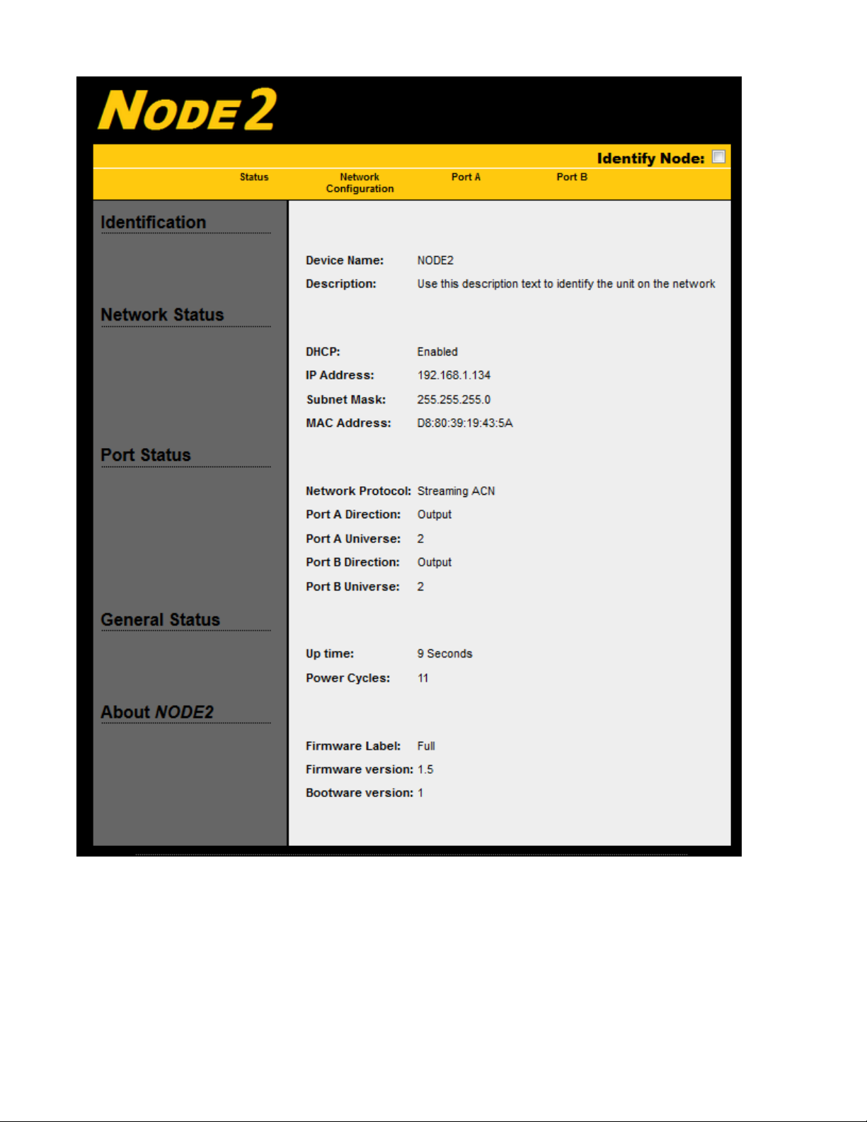
NODE2 ships ready to go, pre-configured for sACN applications. The displays indicate the
universe number associated with the connector below it (for universes 1 - 99). The UP/DOWN
buttons, if not locked out, adjust the universe number. The buttons are locked when a
connector is plugged in; the connector must be unplugged to adjust the universe number. If an
installation prefers the universe number never be changed, a lock-out jumper can be removed
during installation.
The decimal point in each LED display is the DMX512 signal indicator. It will illuminate if there
is DMX512 data on the network for the selected universe.
Upon loss of DMX512 for the selected universe, NODE2will continue to transmit the last
received DMX512 data for three seconds. It then disables the DMX512 line driver allowing
moving lights and dimmers to reset or to let a Preset10 take control of the line.
NODE2 can accommodate up to six sACN sources transmitting the same universe and will
output the source with the highest priority. If two or more sources have the same priority,
NODE2 will merge the sources on a Highest-Takes-Precedence basis. A NODE2 input will be
transmitted with the default sACN priority of 100.
Network Jargon
Doug Fleenor Design strives to make our products reliable and easy to use. Computer
networks, and their complexity, complicate this goal. To help our users de-mystify the network
side of our NODE products, Mr. Fleenor shares some of his insights.
Host. Mr. Fleenor finds this networking term misleading. To non-networking people, a host is
the person that coordinates an event (or picks up the tab at a hosted bar). There is often one
host, and many guests. In a computer network, the term host is used for any device connected
to the network that generates or uses data; on a computer network there are many hosts (and
no guests).
The term host, in computer networks, stems from the days when computers took up entire
rooms or floors. Remote terminals, similar to mechanical typewriters, allowed multiple users to
access the computer. The computer hosting these dumb terminals, was the host. Later these
host computers were connected together to form a network, and the term host, for a computer
on the network, stuck.
Node. Every device connected to a computer network is a node: Switches, hubs, routers,
computers, interface devices... Mr. Fleenor likes this term, thus the name of our network
interfaces. Fun fact: All hosts are nodes, but not all nodes are hosts.
Address. A unique address is required for every device on a lighting control network. sACN
(and Art-Net) use IPv4 addressing which is a 32-bit number, typically written in "dot-decimal"
form (four decimal numbers separated by dots) such as 10.0.1.1. There are two parts to the
Address: the network-part and the host-part. To talk to each other, all devices in the network

Page 5 of 10
must have the same network-part and a unique host-part. Doug Fleenor Design recommends
users use Network 10 (address 10.X.X.X), which is intended for private (dedicated) networks
that are not connected to the internet. Another private network number is 192.168 (address
192.168.X.X). (Author's note: sACN sends DMX512 data on network address 239.255.X.X
regardless of the Node's address or mask. Thus, some aspects of a sACN network may work
even if the address and/or mask do not match.)
Subnet mask. A 32-bit IPv4 address has two parts: the network-part and the host-part. The
number of bits dedicated to each part varies by application and is historically represented by
the subnet mask. The subnet mask is a 32-bit binary number starting with a series of ones,
followed by series of zeros, such as 11111111 00000000 00000000 00000000, with ones
representing network-part bits and zeros representing host-part bits. The subnet mask is
typically written in dot-decimal form such as 255.0.0.0. Although the parts of the IPv4 address
can be split in 31 ways, the two most common in lighting are: 8 bits for network, 24 bits for host
(subnet mask 255.0.0.0) and 16 bits for each (255.255.0.0).
DHCP. The Dynamic Host Configuration Protocol is a tool used to automatically assign
addresses and subnet masks. A device that runs the DHCP is called the DHCP server. Not all
networks have a DHCP server, in which case the addresses and subnet masks are set
manually (DFD products ship with a default address and mask that work in most applications).
Note that DHCP is an app that runs on a computer, router, console, or other device on the
network; it is not a separate piece of equipment.
Network Setup
NODE2 ships with default settings that will work in most applications:
Protocol: sACN
Address: 10.X.X.X (where X.X.X is unique to each unit)
Subnet mask: 255.0.0.0
DHCP: enabled
DHCP. Doug Fleenor Design recommends against using DHCP in an entertainment lighting
control network; it typically adds an unnecessary level of complexity. That said, NODE2 ships
with DHCP enabled in case a server is being used. NODE2 does not save DHCP assigned
parameters and requests them (from the server) each time power is applied. If, upon power-
up, no DHCP server is present, NODE2 will use its stored address and mask.
Changing NODE2's default settings. Editing NODE2's settings, if required, is typically done on
the bench, prior to installation. Configuration can also be edited over the network but having
the Node visible, and within arm's reach, is nice.
Editable setting: Default
Device name NODE2
Description Use this description text to identify the unit on the network
Protocol sACN
DHCP Enabled
Address 10.X.X.X
Subnet mask 255.0.0.0

Page 6 of 10
Port direction Factory set for installed connectors. JP4 resets to two outputs.
NODE2'S settings are edited using its built-in web server. To access the web server, the user
must attach a computer to the NODE2's network, launch a browser application (Microsoft Edge,
Google Chrome, Mozilla Firefox, etc.), and point it to the NODE2. The computer's network
address must match NODE2's network address.
Most computer's network cards are configured to access the internet. To access a NODE2's
web server, the network configuration must be changed to match the NODE2's. Computer
operating systems are constantly changing and can be customized by the user so the following
steps may need massaging.
To point a Windows 10 computer to the node:
Click on the Windows icon in the lower left corner.
Click on the Settings icon (gear looking thing) that appears above the Windows icon.
Click on Network & Internet
Click on Ethernet. If Ethernet is not an option, hard-wired Ethernet capability may be missing.
Click Change adapter options
At this point you should be at >Control Panel>Network and Internet>Network Connections.
Users can get to this panel in other ways, on other versions of Windows.
Click on Ethernet
Click on Change settings of this connection
In the "This connection uses the following items" window,
click on Internet Protocol Version 4 (TCP/IPv4)
Click on Properties
Select Use the following IP address:
In the IP address box, enter 10.10.1.1 (unless someone changed the factory address)
(If the NODE2's factory address has been changed, enter its address incremented by 1)
In the Subnet mask box, enter 255.0.0.0
(If the NODE2's factory subnet mask has been changed, enter its subnet mask)
Your computer is now on the same network as the NODE2.
Launch a web browser such as Google Chrome.
In the URL box, type the NODE2's address (printed on the back of the NODE2 unless someone
changed the factory address).
Press Enter.
With luck, you will see this status page displayed in your browser.

Page 7 of 10
From this page:
Checking the Identify Node box will cause NODE2's display to flash.
Clicking Network Configuration displays the network configuration page.
Clicking Port A or Port B displays the appropriate DMX512 configuration page.

Page 8 of 10
Network configuration page:
The Device Name (up to 20 characters) and Description (up to 64 characters) are fields that
can be queried and displayed by a controller, such as a console, on the network. When editing
these fields it will be necessary to delete or backspace over existing text and trailing spaces.
DHCP can be enabled or disabled. To edit the factory assigned address and mask, the user
must select Disabled. DHCP can then be enabled after editing, if desired. NODE2's default is
Enabled, which works in most applications.
The IP Address and Subnet Mask can be edited here (provided DHCP is disabled). Doug
Fleenor Design recommends against altering the factory assigned values of 10.X.X.X and
255.0.0.0 (where X.X.X is unique).
If the user changes the IP address to 10.X.X.X, the subnet mask should be 255.0.0.0.
If the user changes the IP address to 192.168.X.X, the subnet mask should be 255.255.0.0.
Note that in the graphic above, DHCP has assigned its own address and mask.

Page 9 of 10
Five Network Protocols are supported: sACN (default), Art-Net (also popular), draft sACN
(some ETC products), ShowNet (some Strand products), and KiNET (some Color Kinetics
products).
Remember to click Save Settings before navigating away from this page or changes will be
lost.
Port configuration page:
Port A is the left connector, port B is the right connector.
The direction should never need to be changed; it is assigned at the factory to match the
installed hardware. A "Jumper 4" reset-to-default-values will set both ports to outputs, so if one
or both connectors are inputs, the direction will require editing, following a JP4 reset.
The front panel UP/DOWN buttons allow access to universe numbers 1 through 99. This web
page allows setting the universe number up to 63999. If the web interface is used to set a
port’s universe number to a value greater than 99, the display will show "- -" and the universe
number cannot be changed from the front panel.
Remember to click Save Settings before navigating away from this page or changes will be
lost.

Page 10 of 10
Restoring default settings
To set NODE2 to its default configuration settings:
–Remove power from the NODE2
–Remove jumper JP4
–Re-apply power, wait about 10 seconds
–Remove power from the NODE2
–Re-install jumper JP4
–Re-apply power
The NODE2will have DHCP enabled and the IP address will be the default as shown on the
label on the back of the unit.
Factory default configures NODE2 as two DMX512 output ports. If a unit has input port(s), the
port direction must be changed using the built-in web server.
Node Discovery
A utility program called Node Discovery, along with instructions, is available at
http://www.dfd.com/NodeDisc.html. This Windows program assists in finding and configuring
NODE2s across a network.
Limited Manufacturer’s Warranty
Products manufactured by Doug Fleenor Design (DFD) carry a five-year parts and labor
warranty against manufacturing defects. It is the customer's responsibility to return the product
to DFD at the customer's expense. If covered under warranty, DFD will repair the unit and pay
for return ground shipping. If a trip is necessary to the customer's site to solve a problem, the
expenses of the trip must be paid by the customer.
This warranty covers manufacturing defects. It does not cover damage due to abuse, misuse,
negligence, accident, alteration, or repair by other than by Doug Fleenor Design.
Most non-warranty repairs are made for a fixed $50.00 fee, plus shipping.
Doug Fleenor Design, Inc.
396 Corbett Canyon Road
Arroyo Grande, CA 93420
(805) 481-9599 voice and FAX
(888) 4-DMX512 toll free (888) 436-9512
web site: http://www.dfd.com
e-mail: info@dfd.com
This manual suits for next models
1
Table of contents
Other Doug Fleenor Design Recording Equipment manuals

Doug Fleenor Design
Doug Fleenor Design NODE16 User manual

Doug Fleenor Design
Doug Fleenor Design PRE10ETHER-A User manual

Doug Fleenor Design
Doug Fleenor Design PRE10E-A User manual

Doug Fleenor Design
Doug Fleenor Design NODE1-A User manual

Doug Fleenor Design
Doug Fleenor Design RERUN Series User manual
Popular Recording Equipment manuals by other brands

Command access
Command access PM300ACD installation instructions

Finhol
Finhol Accutronics manual

BLACK NOISE
BLACK NOISE COSMOS Build instructions

Campbell
Campbell SC932C user guide

Philips
Philips CDD260 user manual

Lutron Electronics
Lutron Electronics Grafik Eye GBO-RS232 Installation and operation instructions