
2020/11/08 05:18 3/13 MB-6582 Base PCB Construction Guide
MIDIbox - http://www.midibox.org/dokuwiki/
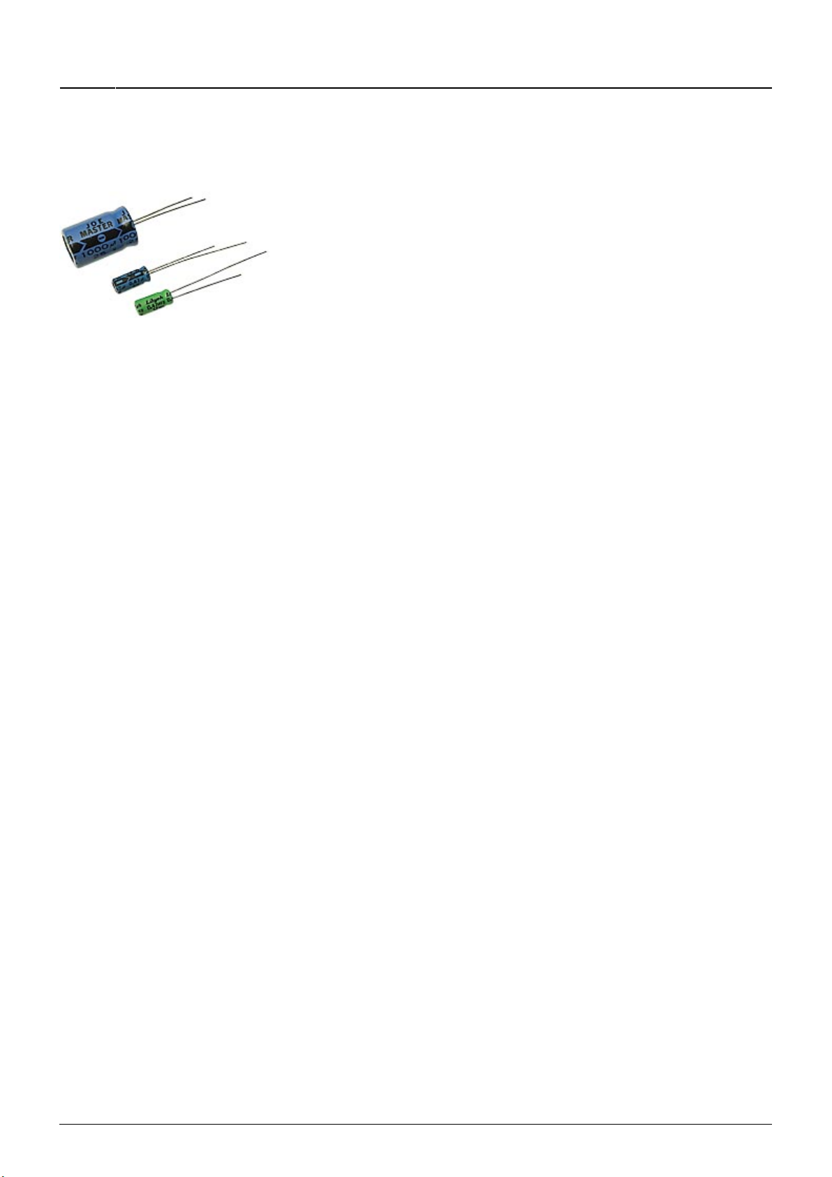
Solder V1, B1, V2, V3, C1, C2, C3, C4, C11, C12.
Do not solder V4, C13, C14, J74
V1 cannot share the same heatsink with V2 and V3, as the heatsink mounts are connected
to the common pin and V1 common pin is connected to 5V, V2 and V3 common pins are
connected to ground
PSU Option C
In options A and B, a 9v AC and a regulated 5v DC power supply come through the power socket and
switch, both generated by the same transformer in the C64 power supply. If people don't have this
power supply, they could connect a 9v AC supply and an additional unregulated 5v DC supply through
the power socket. In this case, J73 is used to divert it to J74 and through the 5v regulator and then
back to J73 and the 5v supply lines. In theory, this will allow option A or B to work, and can generate
9v and 12v supplies. Alternately, people could connect a single 9v AC power supply, then connect the
regulated 9v DC supply at J4:pin3 to J74:pin2, then connect the 5v DC output at J74:pin1 to J4:pin2. In
theory, this will allow option A to work, but option B would not be possible because the 5v is
generated from the 9v supply, it can't be added to the 9v to make the 14v required in option B.
People choosing this solution can work out for themselves what extra wiring, parts and solder bridges
are needed, or they can ask me for help.
PSU Option D
Connect power from your external power supply at J4. If you are only using 8580/6582 SIDs, then 12v
is not required.
If you are using PSU Option D, then you probably know enough about electronics to need no further
help, but I will specify the following anyway:
Do not solder V1, V2, V3, V4, B1, C1, C2, C3, C4, C11, C12, C13, C14, J1, J74, S1
Do not solder bridges at J71, J72, J73
If you want, you can reuse C3 and C4 as extra smoothing capacitors on the 5v supply lines, in which
case bridge J73.
Socket/Switch Options
If you are constructing a base PCB to go with the PacTec PT-10 case like the original MB-6582 (or want
to use the PCB mounted sockets and switch with a different case), then you will need to solder the
PCB mounted sockets and switch at the top of the PCB. So you will need to solder S1, J1, J12, J13, J21,
J22, J23, J24. Although fairly obvious, I'll explicitly tell you… Do not solder J1A, J12A, J13A, J21B,
J22B, J23B, J24B.


