Midwest Shorty Single Speed Motor User manual

Midwest Shorty Single Speed Motor
The Midwest Shorty single speed motor has been in existence for many years. It is a
durable handpiece and has a speed range of 0 – 5000 rpm. It has replaced the Midwest
Tru-Torc and you will come across them quite often in the field. Many aftermarket
replacement parts exist for this handpiece. As always, try to determine the problem
before disassembling the handpiece.
Some of the most common problems and solutions are addressed in the Midwest Tru-
Torc and Shorty troubleshooting guide immediately preceding this section.
Sub Assembly A & B Disassembly
STEP 1
Remove the front sheath housing. Do this by
placing it in a 3/4”collet. All the threads on this
handpiece are regular thread, so turn
counterclockwise to remove.
STEP 2
Lock the drive housing of the handpiece into a 61/64” collet. Loosen the
upper turbine housing by hand and remove. Remove any spacer
washer(s) and keep them in a safe place.
Sub Assembly A Disassembly (Nose Section)
STEP 3
Reach under the drive plate with a flat thin screwdriver. Pry the plate
up. This will expose the three wide drive rings. Place them along side
the drive plate on your work surface.
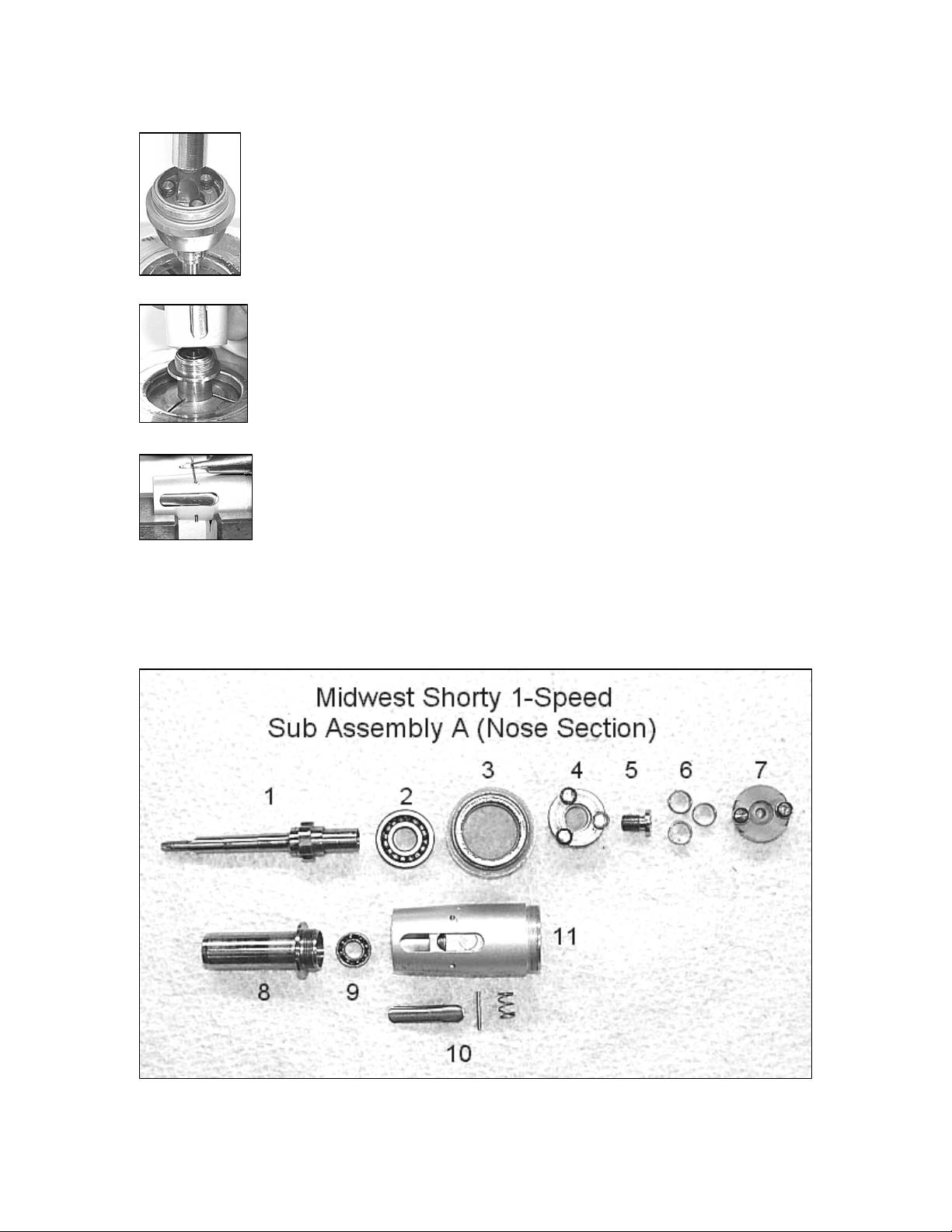
STEP 4
Now that the drive plate and wide drive rings have been removed, place a
3/16” collet into the collet holder. Insert the tip of the spindle, just above
the fork, into the collet. Once the collet is tightened, use a flat head
screwdriver to unscrew the spindle bolt. Then pull the various pieces
apart and place on your work surface.
STEP 5
You can now place the nose piece in a 13/32” collet. Unscrew the sheath
housing from it while simultaneously depressing the latch. This will
keep the flange on the nose piece from being caught up.
STEP 6
If you need to replace the latch on the sheath housing, place it over two
v-blocks. Hold a small punch or pin with a set of tweezers over one end
of the pin in the housing. Gently tap the pin out of the housing and
remove the latch and spring. The replacement latch kit is part# 40503.
STEP 7
You can now place the component parts in your ultrasonic cleaner. After you clean the
parts, align them like the exploded view below and replace what is needed.

Picture
Number Part
Number Description
1 40449A
40449 Spindle With Lock Gear (pictured)
Spindle Without Lock Gear (not pictured)
2 40432 Main Spindle Bearing
3 40493B Drive Housing
4 40437C Single Speed Drive Plate
5 40494A Spindle Bolt
6 40437 Wide Drive Rings
7 40437A Wide Drive Ring Plate
8 40505 Nose Piece
9 40436 Front Spindle Bearing
10 40503 Latch Kit
11 40462A
40462B Sheath Housing Without Button (pictured)
Sheath Housing With Button (not pictured)
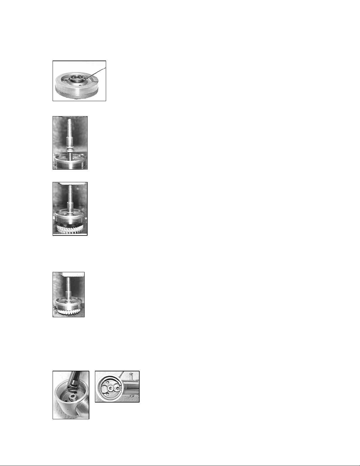
Sub Assembly B Disassembly (Motor Housing)
STEP 8
Remove the allan screw from the side of the motor housing. You
will need to use your .035” allan wrench (20115A). Once again,
unscrew the screw in a counterclockwise fashion.
STEP 9
After you remove the screw, take the drive ring retainer out of
the housing. Also remove the two narrow drive rings.
STEP 10
Insert your turbine raceway tool (00003) into the three
holes in the raceway. Unscrew the raceway from the
housing. If you cannot get the raceway to unscrew, put the
threads of the housing in a 9/16” collet. With the housing
securely held, insert the raceway tool into the raceway and
unscrew.
STEP 11
Remove the vent plug from the housing. Like all threads on this handpiece,
turn counterclockwise to unscrew. Once the plug is out, replace the o-ring
(404072) in the rear of the housing.

STEP 12
To disassemble the turbine, place the drive ring raceway over the largest hole
on your work block (as shown). Then put your Lares disassembly tool
(00024L1) into the end of the motor spindle. Press the spindle and tool
through the raceway.
STEP 13
Now turn the partially disassembled raceway over (see picture). The front
motor bearing must be removed from the raceway. Use your Lares
assembly tool (00024L2) to punch the bearing out of the raceway. Always
replace these motor bearings when performing an overhaul. Place all of your dirty or
fouled parts in the ultrasonic cleaner.
Picture
Number Part
Number Description
1 40446C Turbine Retainer
2 40438 Narrow Drive Rings
3 40446 Drive Ring Raceway
4 40442 Turbine Spindle
5 40433 Front Turbine Bearing
6 40454 Impeller
7 40405C Rear Turbine Bearing
8 20115 Allan Screw
9 40424 1-Speed Turbine Housing
10 404072 O-Ring
11 40501 Shorty Vent Plug (pictured)
Sub Assembly B Reassembly (Motor Section)
STEP 14
Place the turbine raceway upside down on you work surface. Insert
the front turbine bearing into the appropriate hole (as shown). With
the bearing partially inserted, place a small dab of Loctite on the tip
of a needle and apply sparingly under the flange of the bearing.
Press the bearing firmly into the drive ring raceway and let sit.
STEP 15
After the Loctite has cured, center the raceway, bearing side down, over
Hole# 7 in your work block (picture at left). Place the turbine spindle over
the hole in the bearing with the fat side up. Put your Lares assembly punch
in the top of the spindle and press the spindle into the bearing.
STEP 16
Now center the impeller over Hole# 6 in your work block. Place the small
end of the turbine spindle into the impeller (as shown). Using the same
Lares punch, press the spindle into the impeller.
STEP 17
If you did not replace the rear o-ring and vent plug in STEP 11, do so now.
STEP 18
Place the rear turbine bearing (40405C) into Hole # 2 of your work block.
Be sure the balls in the bearing are face down. Put the small end of the
turbine spindle into the bearing. Use the Lares punch to press the partial
turbine assembly into the bearing.
STEP 19
Insert the raceway tool into the three holes in the raceway. Carefully begin to thread the
raceway into the motor housing. A good tip is to turn the raceway counterclockwise until
a click is heard. Then begin to thread the pieces together. Once started, thread the
raceway securely into the housing until it bottoms out.
STEP 20
Now insert the two narrow drive rings into the drive ring
raceway 180 degrees apart with your drive ring tool.
Then place the turbine retainer ring over the drive rings.
Make sure the small cut out portions line up with the hole where the allan
screw enters the housing and where the air exhaust ports are (as shown).

Sub Assembly A Reassembly (Nose Section)
STEP 21
Reinstall the latch kit back onto the sheath housing. Once
this is done, place the front spindle bearing into the nose
piece. Depress the latch and screw the nose piece back into
the housing.
STEP 22
Now place the main spindle bearing onto the back of the
spindle. Put the drive housing on the back of the spindle over
the bearing. Next, insert the single speed drive plate into the
drive housing.
STEP 23
Insert the spindle of this partial nose section into the collet. Place the
spindle bolt into the rear of the spindle. With the assembly locked into the
collet holder (see picture), use a flat head screwdriver to tighten the
spindle bolt firmly.
STEP 24
It is now time to install the three wide drive rings. Insert the wide drive
ring plate into your wide drive ring tool (00017). Follow that by spacing
the three drive rings evenly in the tool (as shown). Grooves are pre cut
into the tool and will properly space the wide drive rings.
STEP 25
With the drive rings properly placed in the drive ring tool, lower the
partially assembled nose section over the tool. Line up the three wide
drive rings between the three black bushings on the drive plate. Once
the two pieces are aligned, mesh them together and press the plunger on the
bottom of the drive ring tool. This will correctly insert the wide drive rings
and plate into the clutch housing.
STEP 26
You now have two properly assembled Shorty halves. Sub Assembly A
and Sub Assembly B. Place any spacing washers that may have been
present back onto the outer edge of the clutch housing. Now mesh the
two drive plate bearings into the two narrow drive rings in the
motor housing. Once these are correctly aligned, begin to thread the
two halves together. Be sure not to cross-thread the pieces. If the pieces
seem to stop threading together right before they look properly seated, STOP. You may
not have the drive plate bearings aligned exactly inside the narrow drive rings. Back the

pieces a part 1/16th of a turn and retighten. If they still don’t align, unscrew the pieces
and start this step over. Forcing Sub Assembly A and B will cause the LocTite to be
broken loose on the turbine.
STEP 27
To firmly tighten the two assemblies together, once again, place the sheath
housing into the ¾” collet. Wrap the motor housing with a strip of rubber
and tighten in a clockwise motion.
Table of contents
Other Midwest Engine manuals

Popular Engine manuals by other brands

woodmizer
woodmizer D10 Safety, Operation, Maintenance & Parts Manual

GiBiDi
GiBiDi RUNNER REB35 6/28 Instructions for installation

woodmizer
woodmizer LT30 Safety, Operation, Maintenance & Parts Manual

Hobby-Wing
Hobby-Wing XERUN 4268 G3 user manual

BE Power Equipment
BE Power Equipment Powerease RV740E owner's manual

HQ Power
HQ Power VDLMM3N user manual


