Midwest 140 User manual

Mid-West
®
Instrument
Electrical Installation and O
p
eratin
g
Instructions - Model 140
Bulletin No: Elec IM140/18A
Supersedes Elec IM 140/16B
6500dobrydrsterlingheights,mi48314
1.0 Safety
Beforeinstalling,checktheModelNumberandverifycompatibilitytotheprocessmediaand
temperatureincontactwiththewettedparts.Incompatiblemediaand/oroperationat
temperatureextremescancauseprematuredegradationofmaterialswhichcouldresultinsafety
risktopersonnel.
Verifytheselectedpressurerange(differentialpressureandworkingpressure)andtheswitch
ratingsarewithinspecificationforyourapplication.
Warning!Performallelectricaladjustmentswithpowerremoved.
TheModel140productutilizesadiaphragmdesignwhichisolatesthehighprocessfromthelow
process.Foroverpressureconditions(HighoverLowandLowoverHigh)thediaphragmis
supportedattheendoftravelfortheratedworkingpressureofthegauge.However,itis
recommendedthatiflargepressurespikesexist,somesortofpressurelimitingdeviceshouldbe
installedforprotection.
Warning!Remainingmediamayresultinarisktopersonnel,environmentetc.Usesufficient
precautionarymeasureswhenremovingandtransportingtheproduct.
Warning!Ifinstallingproductwithinanotherenclosurethatispressuretight,pleaseverifyall
processconnectionareleaktight.Leakagewithinapressuretight(ieNEMA4X)enclosurecould
causeapressurebuildupwithintheenclosureandcauseaburstscenario.
1.1 Intendeduse
Theindicating/non‐indicatingdifferentialpressureswitchesortransmitterareusedformonitoring
differentialpressuresinindustrialapplications.
Themanufacturershallnotbeliableforanyclaimsiftheproductisusedinapplicationscontrarytothe
intendeduse.
1.2 Personnel
Personnelinstallingandputtingthisinstrumentationintoserviceshallbesuitablytrainedandqualifiedin
accordancewithlocalcodes,practicesandregulations.
1.3 Labeling/Marking
ThefollowingElectricalConfigurationsbearthismarkandcomplywiththerelevantEuropeanDirectives
identifiedonthedeclarationofconformity:A,B,E,F,T,W
Thefollowingelectricalconfigurationsbear1orbothofthesethirdpartylistingagencymarksfor
productevaluatedtobothUSandCanadianStandards:E,F,W
Electrical Installation and O
p
eratin
g
Instructions - Model 140
6500dobrydrsterlingheights,mi48314Page2
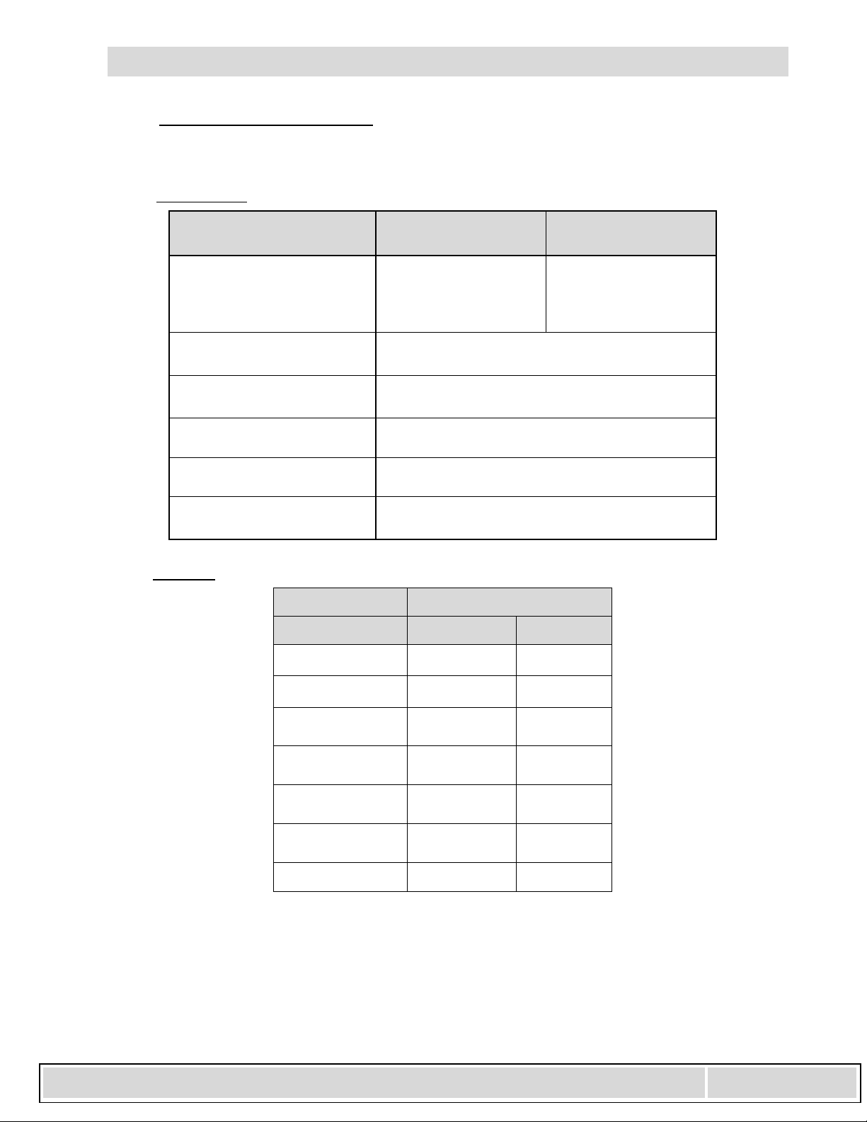
2.0 GeneralSpecifications
Non‐electrical
Electrical
*Productoftheswitchingvoltageandcurrentshallnotexceedthepowerratingofthedevice.
**Exceptwhereotherwisenoted
ParameterLimits(Std)Limits
(HazardousLocations)
WorkingPressure(PSI)
3000(AL)*NonHaz‐Loc
1500(Br)NonHaz‐Loc
3000(SS)*NonHaz‐Loc
1500(BrNonEnd)
3000(Al/SSNonEnd)
2000(AL/SSEndConn.)
1625(Al/SSNace)
ProofPressure4XRatedWorkingPressure
Temperature‐40°to200°F(Switches)
-20F to 150F (Transmitter)
DifferentialPressureRange
(PSID)0‐50”H2Oto0to100PSID
IndicatorAccuracy
ASMEB40.1002%
DPOver‐Range+/‐Proofpressure
SwitchSpecification
Parameter SPST (NO) SPDT
Option:BA
*Power25W3W
Max.Current0.5Amps0.25Amps
Max.Voltage
VAC/VDC240125
**Setting
(%F.S.)15to9515to95
Hysterisis
(Max/Nom)
15%/8%
(F.S.)
10%/5%
(F.S.)
Repeatability1%F.S.1%F.S.
Electrical Installation and O
p
eratin
g
Instructions - Model 140
6500dobrydrsterlingheights,mi48314Page3
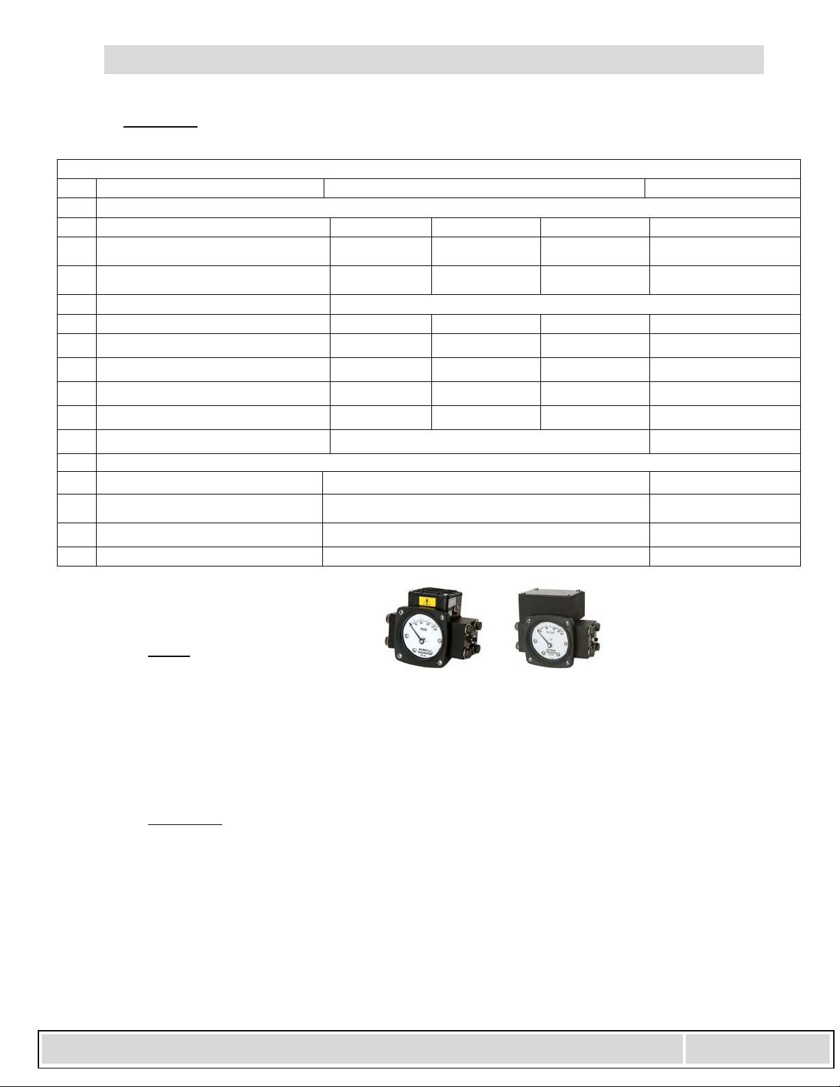
Transmitter
3.0 ProductDescription:
Switch
Aflexibleelastomerdiaphragmandcalibratedrangespringaremovedbydifferentialpressure.A
magnet,coupledwiththediaphragm,transmitthismotionthroughthewallofthepressurehousingtoa
followermagnetattachedtoanindicatingpointer.Therotationofthefollowermagnetcausesthe
pointertotrackthemovementoftheinternalmagnetandindicatethedifferentialpressureonthedial
scale.Theswitchesarealsomagneticallyoperatedandarelocatedoutsideofthepressurehousing.The
switchesaremechanicallyadjustableallowingthecustomertosettheswitchwithinadefined
adjustmentspanoftherangeoftheinstrument.
Transmitter
TheModel140indicating/non‐indicatingdifferentialpressuretransmitterisa2wirelooppowered
microprocessorbased4‐20matransmitter.Themagneticanglesensor&electronicssensestheangle
(relativetothetransmittersensor)ofthemagnetwhichmoveslinearlyinthebore.Eachtransmitteris
individuallycalibratedtothegaugeusingan11pointcalibrationlinearizationtechnique.Thismethod
resultsina<2%fullscaleaccuracyfortheupper80%oftherange.
Transmitter Specifications: (Calibrated on Increasing pressure) Comments:
Operating Temperature (Max.) -20F - 150F
ELECTRICAL:
Min Typ Max
Transmitter Accuracy (FSR) 2% Upper 80% of Full Scale
Range
Supply Voltage (3) (Vdc) 8 28 Pin 3 Reverse Polarity
Protected
Output Current (ma)
Zero Floating (2) 4.0 – 20.1 ma 4.0 – 21.0 4.0 – 22.0 Pin 2
Zeroed (1 connected to 2) 8
V
oltage (Pin 2 to 1) 4.8 6.3
Zero Time (seconds) 2
Max Loop Resistance (ohms) 1000
Max Loop Resistance Formula ((Vs – 8)*1000)/ 20
INTERFACE:
Electrical:
Connections: 4 Position Terminal Strip; ½” NPT Conduit
1= Rtn, 2= Zero, 3 = 8-28 Vdc In 4= Chassis 22 Awg – 16Awg Wire
Environmental Rating: NEMA 4X
Certifications: CSA (Canadian & US Standards; Division 2 Locations)
Electrical Installation and O
p
eratin
g
Instructions - Model 140
6500dobrydrsterlingheights,mi48314Page4
4.0 Installation:
MechanicalConnections
¼”FNPTareprovidedstandard,howevercheckyourpaperworktoconfirmtheconnectionsordered.
Thereare2connectionsidentifiedonthegaugebodyas“Hi”and“Lo”forHighpressureandLow
pressurerespectively.Besuretheseareplumbedproperlyinyoursystem.Improperconnectionwillnot
damagetheinstrument,butitwillnotfunctionproperly.
Donotallowgaugefittingstorotatewhenmakingprocessconnections.Calibrationand/or
pressureratingoftheproductmaybecompromised.
Forendconnectedorgaugessuppliedwithadapterfittingsusetwowrencheswhenmakingconnections.
Useonewrenchtoholdthepressureportfittingonthegaugeandtheothertotightentheprocesspipe
oftubefitting.
InstrumentLocation:
Onliquidservicetheinstrumentshouldbemountedbelowtheprocessconnectionstofacilitateself‐
bleeding.Ongasserviceitshouldbelocatedabovetheprocessconnectionstopromoteself‐draining.If
theprocesscontainsparticulates,apigtailloopordropleg(manometer“U‐tube”configuration)inthe
tubingwillminimizethepossibilityofitmigratingintotheinstrument.
TemperatureLimitations:
Forprocesstemperatureshigherthantheratedtemperatureofthedpgauge/switch,useprocess
tubingtoreducethetemperature.Ageneral“ruleofthumb”isthatforhorizontaltubingrunsthetemp
dropis100°F/ft.Anotheroptionistouse“coolingtowers”toprotecttheinstrument.
Verifytheselectedelastomeroptionisappropriateforyouroperatingtemperature.
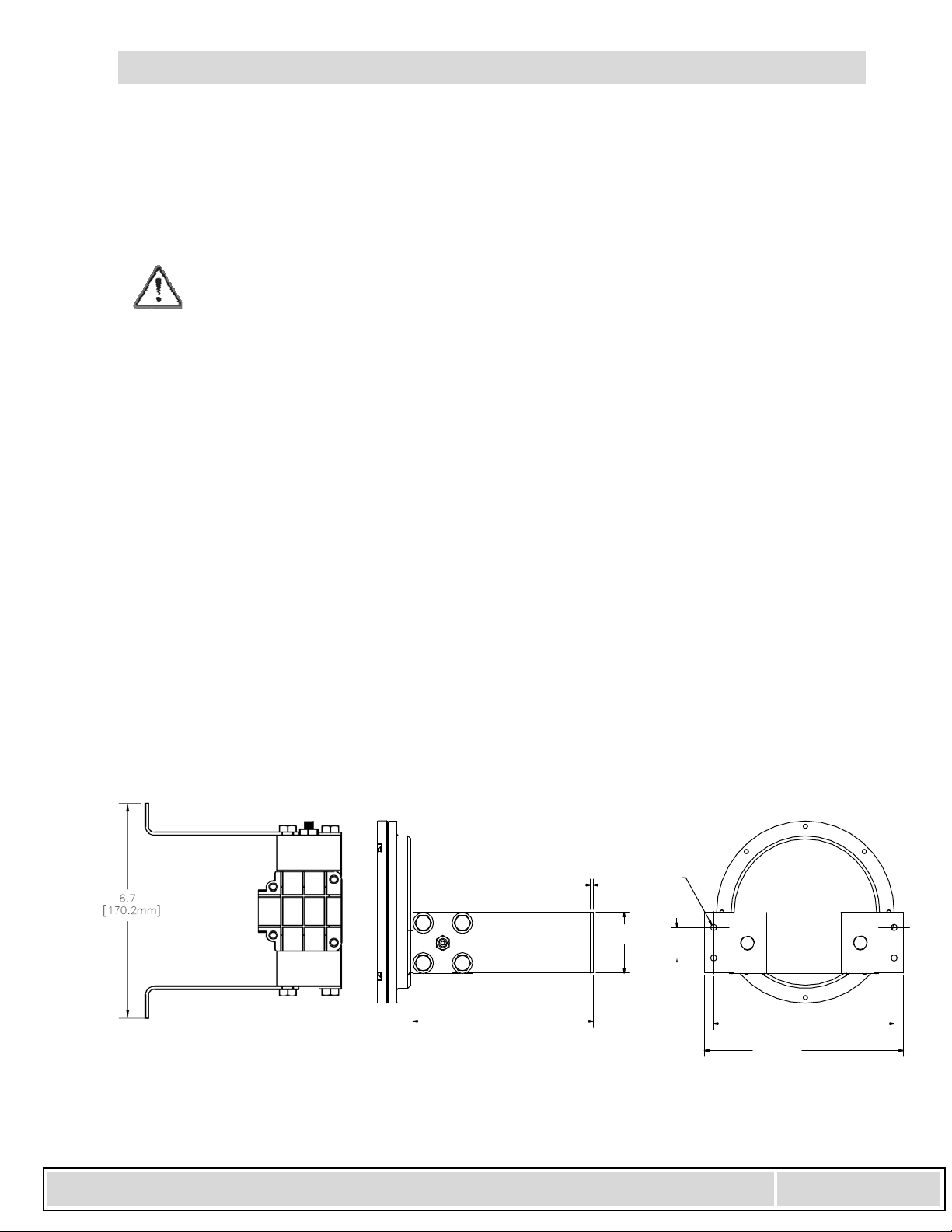
Wall/Pipe/PanelMounting:
Notallcombinationofoptionscanbewall,pipe,orpanelmounted.Ifyourunitissuppliedwithawallor
panelmountpossibleconfigurationsareshownbelow:
WallMountConfigurations:
WALLMOUNTBRACKET(NoSwitchShown)
0.09
[2.3mm]
1.00
[25.4mm]
2.00
[50.8mm]
Ø.205[5.2mm]
THRU
(4)HOLES
6.07
[154.2mm]
6.70
[170.2mm]
6.08
[154.4mm]

Electrical Installation and O
p
eratin
g
Instructions - Model 140
6500dobrydrsterlingheights,mi48314Page5
PipeMounting
PipemountingbracketsarenotavailableforanyElectricalConfigurationsinthereverseport
configuration.
PanelMount
Gaugeswith2½”dialscanonlybemountedthroughtherearofthepanel.Maketheproperpanel
cutoutasshownbelow.Removethe(4)bezelscrewsandinsertthegaugefrontthroughtherearofthe
panel.Reinstallthebezelscrewsthroughthefrontofthepanelandintothegaugebezel.Tightenscrews
securelyinanalternatingdiagonalpattern.
Gaugeswith3½”dialsshouldbemountedfromthefrontofthepanel.Contactthefactoryformounting
anddimensionalinformation.
Gaugeswith4½”dialsshouldbemountedfromthefrontofthepanel.Makethecutoutasindicted
below.Insertthe(4)panelstuds,fingertight,intothemetalinsertslocatedintherearofthebezel.
Insertthegaugethroughthepanel,aligningthepanelmountingstudswiththeholesinthepanel.Install
the(4)8‐32nutsontothestudsandtightensecurely.
6.22
5.24
P
2.81
3.80
2.81
.70
.15
1.16
Typical2”PipeMounting

Electrical Installation and O
p
eratin
g
Instructions - Model 140
6500dobrydrsterlingheights,mi48314Page6
45°
Ø3.00(76.2)
Ø3.50(88.9)
Ø0.19(4.7)
(4HOLES)
Typical2½”PanelMount
3.30
3.39
.56
5.30
1.10
Ø5.30(134.6)
Ø5.63 (143.0)
Ø0.19 (4.7)
(4 HOLES)
BOLT CIRCLE
Typical4½”PanelMount
6 in. DIAL PANEL CUT-OUT
MODEL 140
BOLT CIRCLE
Ø0.19 (4.7)
(4 HOLES)
Ø6.50 (165.1)
Ø7.00 (177.8)
#8‐32SCREW
(4PLACES)
PANEL

Electrical Installation and O
p
eratin
g
Instructions - Model 140
6500dobrydrsterlingheights,mi48314Page7
5.0 Electrical:
Warning:Electricalconnectionsshouldbeperformedbyqualifiedpersonnelandmeetthe
representativecountry'snationalelectricalcode.
Warning:Failuretoconnecttotheprotectiveconductorterminalmayresultinashockhazard.
Warning:Performallswitchadjustmentswithpowerremoved.Useanohmmeterorequivalentto
monitorcontactoperation.
Caution: Preferenceshouldbegiventosettingtheswitchpriortoinstallation.Itisalsorecommended
toperformadjustmentsusinganon‐magneticPhilipsscrewdriver.
General
Allswitchtypesarefieldadjustable.Thedefinedrangeoftheadjustmentisspecifiedinthetableabove.All
switchescomewithadecaltoidentifyadjustmentdirectiontoincreasethesetpoint.
SwitchSetPointAdjustment
Caution:Donotconfusetheswitchadjustaccessastheswitchadjustscrew.
Note:Switchescanbesetbelowthedefinedminimumsetpointhowever,theswitchmaynotremain
activatedatmaximumPSID.Iftheunitissetbelowthedefinedminimumsetpoint,thecustomershould
verifythattheswitchremainsactivatedfromthesetpointto
overrangeofthegauge.
Theswitchmaybesetusingtheindicatingdialasa
reference(unitswithadial)orbyusingareferencepressure
gauge.
Forsettingonincreasingpressureincreaseyourpressureto
thedesiredsetpoint.Increasetheswitchsetpointabove
thedesiredswitchset(switchdeactivated).Slowlydecrease
theswitchsetpointuntilthecontactactivates.
ContactProtection:
Providestandardprotectiontechniquesfortheswitchcontactsforcapacitiveandinductiveloads.Use
currentlimitingtechniquesneartheswitchtoprotectthecontactsduetohighinrush(i.e.;inlineresistoror
inductor)forlongcableinterfaces.Provideclampingdevicesatornearinductiveloads(i.e.;relay).
Maximumwirelengthbetweenthe3Wswitchanditsloadshouldnotexceed70–100Feet
for120VACapplications.WerecommendthatyouusetheSPSTswitchoruseacurrent
limitingresistorwiredinseriesandlocatedneartheswitch.Contactthefactoryforassistance
regardingthiscondition.(ForhazardousLocationstheresistoroptionisnotallowed)
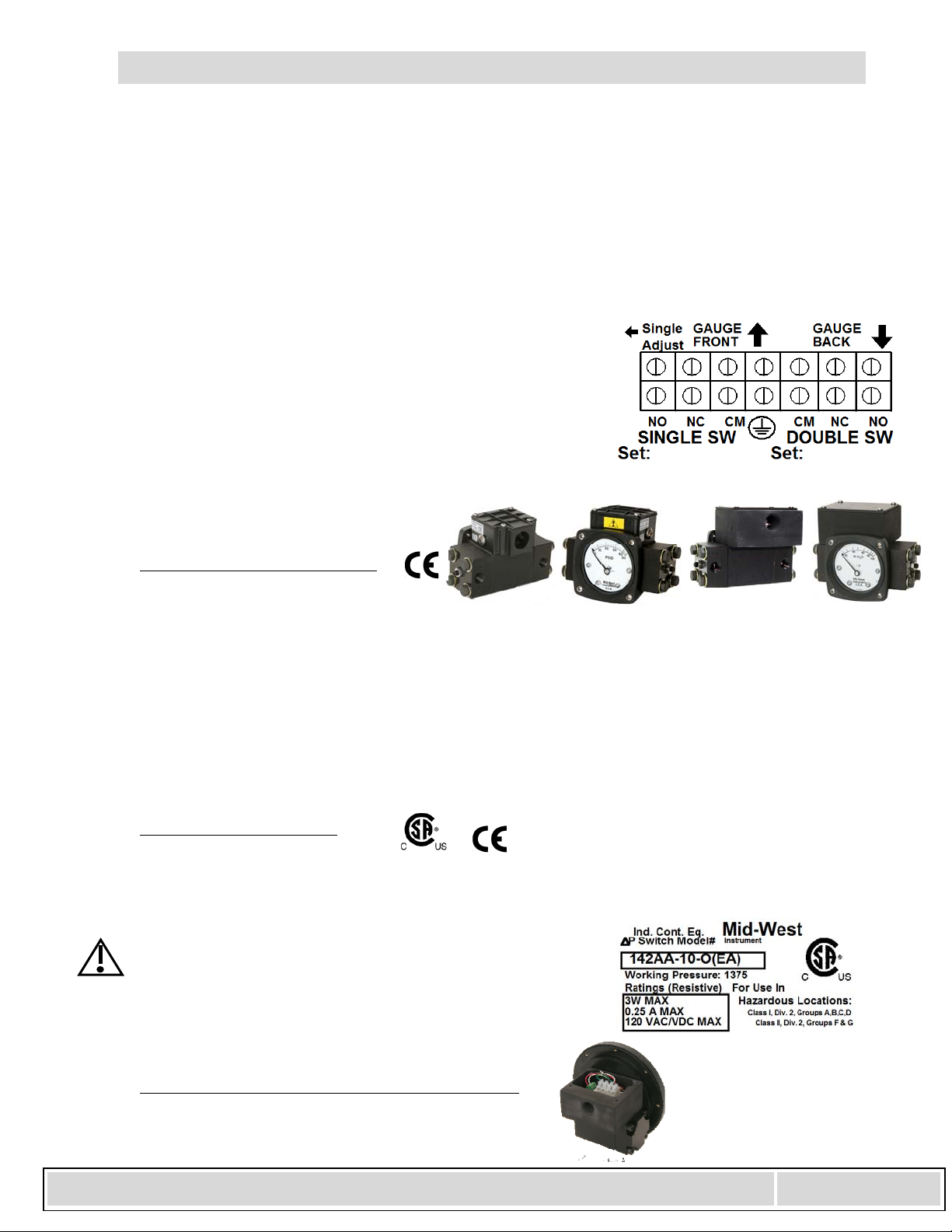
Connections:
Warning:Whenwiringtotheterminalstrip,makesureallwirestrandsarecontainedwithin
theterminalconnection.
SwitchAdjust
Access
Electrical Installation and O
p
eratin
g
Instructions - Model 140
6500dobrydrsterlingheights,mi48314Page8
Thereedswitch(es)arelocatedinsidetheenclosure,onthetopofthepressurehousing(standardport),and
areconnectedtoa7positionterminalstrip.Anopeningisprovidedattherearoftheenclosurefora1/2"
flexibleweather‐proofcableorconduitconnector(suppliedbycustomer)(A&BElectricalConfiguration)ora
½”FNPTconduitinterface(E&FElectricalConfiguration).Uponrequesttheholemaybesizedto
accommodateaPG‐11cableglandconnector.
Toaccesstheterminalstripremovetheswitchenclosurecoverbyremovingthe(4)screws.Insertwires
throughanappropriate(notsupplied)weatherproofconnectorintotheenclosureandconnecttothe
terminalstrippertheterminalstripdiagramshownbeloworontheundersideoftheswitchenclosurecover.
Thecenterconnectionisforconnectionofaprotectiveconductorandisconnectedtothebodyofthe
pressuregauge.
Theterminalstripwillacceptwiresintherangeof22Awg‐16Awg..
Reinstallthecover,gasket,and(4)screws.(Fig.3)afterconnectionof
fieldwiring.
WiringfortheSPSTswitchesisconnectedbetweenNOandCM
connectionsontheterminalstrip.Normallyclosedswitchesare
generallynotavailable.Pre‐setswitcheswillhavetheirsetpoints
identifiedonthelabel.
ElectricalConfigurationsA,B,E,F
ElectricalconfigurationsA,B,E,&Fcan
beusedinPollutiondegree3IndustrialtypeareasTheseconfigurationsareratedNEMA4XIP65.
TheenclosureforConfigurationA&Bisamoldedplastic,whereastheenclosureforconfiguration’sE&Fare
madefromAluminum.
Note:ConfigurationA,&B,hasanelectricalaccesshole(.875).ConfigurationsE&Fhasa1/2”FNPT
conduitinterface.ThesafetyevaluationandtheNEMAratingsfortheseconfigurationswasperformed
withthisaccesssealed.
Areverseportgaugehastheswitchhousinglocatedonthebottomofthegaugebody
ElectricalConfigurationsE&F:
TheE&FElectricalConfigurationare3RDpartycertifiedforClassI,DivisionII,GroupsA,B,C,&D,ClassII,
GroupsF&Ghazardousenvironments.TheCSAmarkidentifiestheproducthasbeentestedtothe
applicableUSstandardsandCanadianstandards.
Warning!Pleasenotethepressureratingsonthe
HazardousLocationsTag.Maxworkingpressures
arereducedforHazardousLocationsto1375PSID
forallmaterials
ElectricalConfigurationsTorW:(TransmitterOption)
Electrical Installation and O
p
eratin
g
Instructions - Model 140
6500dobrydrsterlingheights,mi48314Page9
Intendeduse:
TheModel142TransmitterisintendedforuseinGeneralPurposeLocations(Telectricalconfiguration)or
Division2hazardouslocations(Welectricalconfiguration).InbothcasestheenclosurecarriesaNEMA4X
IP65environmentalrating.
Description:
ThetransmitterassemblyifCEmarkedisalsocompliantwithEMCDirective2004/108/EC.Thetransmitter
hasafactoryprogrammedlow‐passfilter.Thefilterissettoapproximately1second.Thiscanbeincreased
ordecreaseduponcustomerrequestatthetimeoforder.
Note:Thetransmittercircuitrysensesthepositionofamagnet.Anymagneticobjectlocatednearthegauge
mayaffecttransmitteraccuracy.
Thetransmitterifnecessarycanbezeroedbyjumperingpin2toGndpin1momentarilyfor2seconds(with
theunitpowered).Inmostcasesthiswillneverbenecessaryasthetransmitterisprogrammedtogeneratea
4maoutputforthefirst4%oftheFSR.
Warning: IfzeroingintheHazardousLocationenvironmentuseaswitchapprovedforthatlocation.
Caution: Donotzerothetransmitterwithpressureapplied.Otherwiseyourproductwillhavea
negativeoffsetequivalenttothepressurewhenthezerowasactivated.
Caution:Donotattempttorepositionthetransmitterassemblywithintheenclosure.Thisvoidsthe
warrantyandwill“knock”theunitoutofcalibration.Disassemblyandre‐assemblyofany
internalprocesspartswillalsorequiretheunittobere‐calibrated.Calibrationmustbe
performedatthefactory.
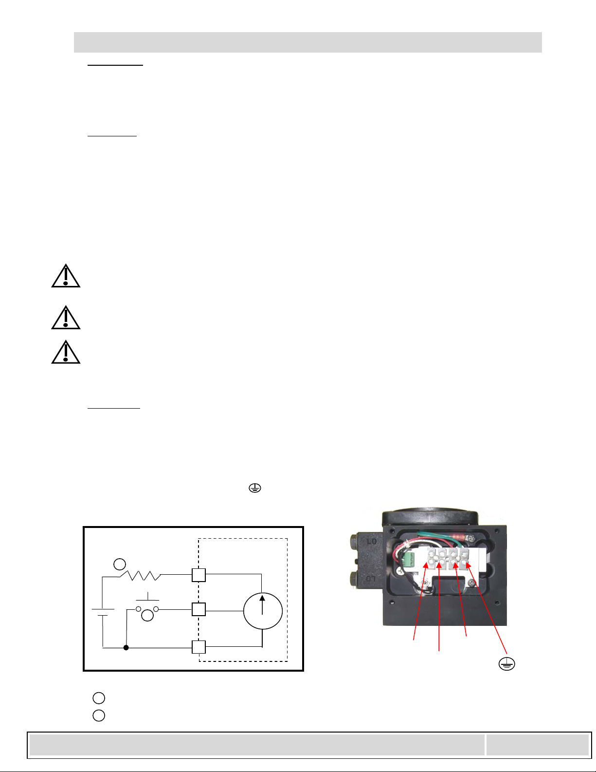
Connections:
Theweather‐proofenclosurecomesstandardwitha½”FNPTconduitinterface.Theinternal4position
terminalstripacceptswiresizes22AWG–16AWG.
Toaccessthe4positionterminalstrip,removethe4coverscrewsfromtheenclosure.Connectlooppower
betweentheconnectionslabeled8‐28VdcandReturn(seeFigurebelow).Connecttheprotectiveconductor
wiretotheterminalidentifiedwiththesymbol.SeetheInterfaceschematicbelow.Pleasenotethatthe
looppowersensingdevicecanalsobelocatedinthegroundleg.
RLoo
p
To Transmitter
8-28 Vdc Pin 3
To Transmitter
GND Pin 1
Interface Schematic
8-28Vdc To Transmitter
Zero Pin 2
4-20 ma
3
2
1
DP Transmitter
Customer Interface
1
2
1 Optional remote zero (customer supplied)
2 Loop Resistor can be located in the ground leg
Zero
Return
8-28
Electrical Installation and O
p
eratin
g
Instructions - Model 140
6500dobrydrsterlingheights,mi48314Page10
Warning:Whenwiringtotheterminalstrip,makesureallwirestrandsarecontainedwithin
theterminalconnection.
Themaximumloopresistanceis1000ohms(@28VdcInput).Usethefollowingformulatodeterminethe
maximumloopresistanceatotherinputvoltages:((Vs–8)*1000)/20)
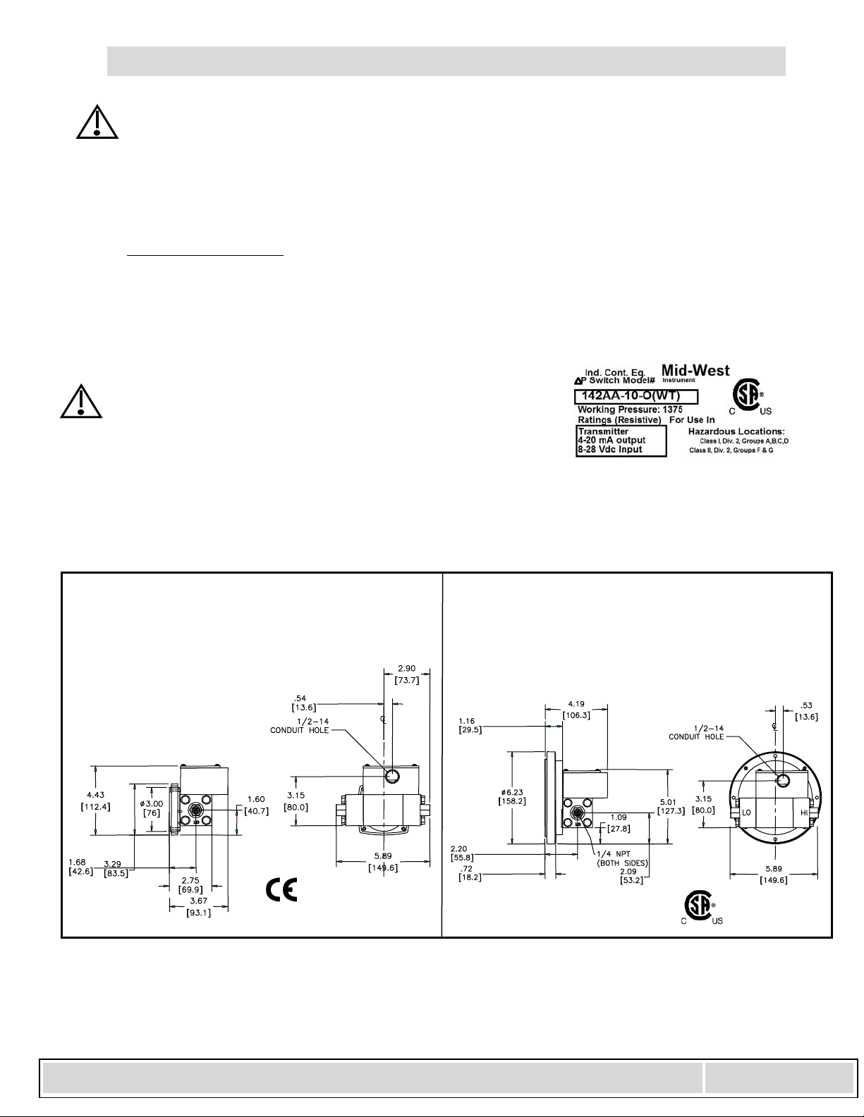
ElectricalConfigurationW:(Transmitter)
TheWElectricalConfigurationis3RDpartycertifiedforClassI,DivisionII,GroupsA,B,C,&D,ClassII,
GroupsF&Ghazardousenvironments.TheCSAmarkidentifiestheproducthasbeentestedtothe
applicableUSstandardsandCanadianstandards.
Warning:PleasenotethepressureratingsontheHazardous
LocationsTag.Maxworkingpressuresarereducedfor
HazardousLocationsto1375PSIDforallmaterials
6.0 Dimensions
ElectricalConfiguration:TorW
Model140/141EndConnected
WithTransmitter2½”Dial
ElectricalConfiguration:TorW
Model140/141EndConnected
WithTransmitter4½”Dial
Woption=ClassI,Div.2,GroupsA,B,C,D
ClassII,Div2,GroupsF& G

Electrical Installation and O
p
eratin
g
Instructions - Model 140
6500dobrydrsterlingheights,mi48314Page11
6.0Dimensions(cont.)
DIM 2 ½ 2 ½ 4 ½
A 7.12
(180.9) 6.53
(163.3) 8.50
(215.9)
B 4.15
(105.4) 2.12
(53.84) 2.50
(62.5)
C 3.15
(80.01) 3.12
(79.24) 4.35
(110.5)
D 6.00
(152.4) 6.56
(166.6) 6.25
(158.8)
E 8.75
(222.2) 7.75
(196.9) 9.12
(231.6)
F 7.35
(186.7) 6.68
(169.7) 7.75
(196.9)
G 3.80
(96.52) 3.80
(96.52) 3.80
(96.52)
H 8.12
(206.3) 7.43
(188.7) 7.75
(196.9)
2½”DIAL
DialSize
ElectricalConfiguration:AorB
NEMA4X4½INCHDIAL
ElectricalConfiguration:AorB
NEMA4X2½INCHDIAL
ElectricalConfiguration:EorF
NEMA4XMETALENLOSURECLASSI,DIV.2,GROUPSA,B,
C,DCLASSII,DIV2,GROUPSF&G
ElectricalConfiguration:CorD
Explosion‐proofEnclosuresClassI,GroupsC&D
ClassII,GroupsE,F&G

Electrical Installation and O
p
eratin
g
Instructions - Model 140
6500dobrydrsterlingheights,mi48314Page12
7.0Troubleshooting
A. Gaugeaccuracyandsetpointproblems:
i. Verifyyourprocessconnectionsareplumbedproperly
ii. Verifygaugeisnotinanelectromagnetic/magneticenvironment.i.e.;closeproximitytohighcurrent
powerlines.
iii. Verifythepointerhasfluidmovementaspressureincreases.Nomovementmayindicateablown
diaphragm.
iv. Allotherscontactthefactoryforassistance.
B Switchdoesn'tfunction
i. Makesurethattheswitchloaddoesnotexceedthespecifiedwattageratingoftheswitch.(steady‐state
andtransient).Contactfactoryforassistanceforexcessiveloads,otherwiseproceedtothenextstep.
ii. Performacontinuitycheckoftheswitchcontactsbytryingtoactuatetheswitchusinganexternal
magnet.Anoperationalswitchusuallyindicatesaproblemwiththegauge.Ifnotoperationalproceed
tothenextstep.
iii. Verifythereedswitchwiresareconnectedtotheterminalstrip(NEMA4Xenclosureonly).Contact
thefactoryforassistanceiftheswitchisconnectedand/orrequestan"RGA"number.
C.Transmitterdoesn'tfunction
i. Makesureyouhavesuppliedpower(propervoltage)totheunit.
ii. CheckthatyouarewiringtothecorrectInterfaceterminals.
iii. Checkthetransmitterinterfacestotheterminalboardforlooseconnections.
iv. Makesurethattheloopresistancedoesnotexceedthespecifiedrating.
v. Makesureyoudidnotzerotheunitwithpressureapplied.Tryare‐zeroat0pressure.
8.0Misc:
CEMarkingStatements:
LowVoltageDirective
TheElectricalConfigurationsA,B,E,F,ofthisproductareCEmarkedincompliancewiththeLowVoltage
DirectivetoEN‐61010‐1.ElectricalconfigurationsTandWfalloutsidethescopeofthedirective.
ATEXDirective94/9/EC
Model140producthasnotbeenevaluatedtotheATEXdirective.

Electrical Installation and O
p
eratin
g
Instructions - Model 140
6500dobrydrsterlingheights,mi48314Page13
PressureEquipmentDirective:
ThePressureEquipmentDirectivehasbeendeterminedtobenon‐applicableforCEmarkingforGroup1
applicationsbelow200barorGroup2applicationsbelow1000bar..Theseproductsaremanufacturedin
accordancewitharticle3,paragraph3ofthedirective,“soundengineeringpractice”.Theyfallbelow
categoryIfornon‐hazardousgases,hazardousliquids,&non‐hazardousliquids.Thisproductalsofallsbelow
categoryIforhazardousgasesatorbelow200bar.
EMCDirective(2004/108/EC):
Optionally,transmitters(ElectricalConfigurationsT&W)maybeCEmarkedforcompliancewiththeEMC
Directive2004/108/EC.Thetransmitterdesignhasbeenevaluatedtoandpassedthefollowing“EN”
StandardsastheyrelatetotheEMCdirective.
EN 61326:2013 Environment Industrial, Electrical Equipment for measurement, Control and
Laboratory use,
EMC requirements from which:
EN55011:2009 + A1:2010 Emission, Class B
EN61000-4-2:2009 Electrostatic discharge (ESD) immunity
EN61000-4-3:2006 +A1:2008 Radiated EM field immunity
+A2:2010
ENV50204:1995 Radiated EM field immunity from digital telephones (GSM)
EN61000-4-4:2004 +A1:2010 Electrical fast transient (EFT) immunity
EN61000-4-5:2006 Surge transient immunity
EN61000-4-6:2009 RF conducted immunity
EN61000-4-8:2010 Power Frequency magnetic field immunity
ForallotherconfigurationstheEMCDirectiveisnon‐applicable.
ROHSDirective:
TheelectricalConfigurationsA,B,E,FofthisproductareCEmarkedincompliancewiththeRoHsdirective
2011/65/EU(RoHs2).ElectricalConfigurationsT&WwillbeCEmarkedforcompliancewithRoHS2whenthe
productismarkedforcompliancewiththeEMCDirective.
Warning: Thesuitabilityoftheapplicationandinstallationofthisdifferentialpressure
switch/transmitteristheresponsibilityoftheenduser.Theapplicable
certifications,listingsapplytothedifferentialpressureswitch/transmitteronly.
STANDARDS:AllModel142Seriesdifferentialpressuregaugeseitherconformtoand/oraredesignedtothe
requirementsofthefollowingstandards:
ASMEB1.20.1 NACEMR0175
ASMEB40.1 NEMAStd.250
EN‐61010‐1 ULStd.No.50,508,&1604
CSA‐C22.2No.14,25,,&213
Table of contents


