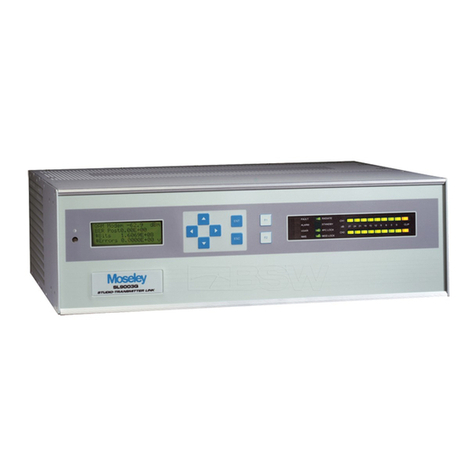
Moseley PCL-303/C User manual

--+-
]
1
INSTRUCTION
MANUAL
MODEL
PCL-
303/C
STUDIO·TRANSMITTER
LINK
MOSELEY
A.SSOCIATES,
INC,
Santa
Barbara
Research
Park
III
Castilian
Drive
Goleta,
California
93017
March,
1968

INSTR
UCTION
MANUAL
MODEL
PCL-
303/
C
STUD10-TRANSMITTER
LIKK
Table
of
c.:')ntents
Introduction
Unpacking
and
Initial
Checkout
In
stallation
Antenna
Specification
6
Page
1
3
4
5
6
1)
Transmitter
Operation
6
2)
Transmitter
Circuit
Description
8
3)
Transmitter
Nominal
Performance
Specifications
10
4)
Transmitter
Adjustments
and
Alignments
11
5)
Receiver
Operation
12
6)
Receiver
Circuit
Description
13
7)
Receiver
NOlTlinal
Performance
Specifications
15
8)
Receiver
Adjustments
and
Alignments
16
PCL-
303/
C
3/68

INSTRUCTION
VtANUAL
MODEL
PCL-303JC
STUDIO-TRANSMITTER
LINK
Ir :
t!"
odu
etian
The
\,lodel
PCL-303!C
Composite
Aural
Studio-Transmitter
Link
(STL)
is
a
\\"ide
band
communications
system
designed
ior
the
tran.<;-:ilission
of
a
composite
F\1
stereophonic
signal
between
a
broadcc;.st
studio
and
u
'remotely
located
FM.
tra.T'.srr..itter
.
Rug-
gedly
built,
compact,
and
rated
for
continuous
duty,
the
Model
PCL-303/,C
is
ar..
all
solid-state
unit
emplo")-ing
only
silicon
semi-
conductor
s.
There
are
several
advantages
to
such
a
transrnlssion
technique.
Some
of
these
are:
1.
Only
one
basic
RF
link
is
utilized
to
transmit
the
composite
ster
eo
waveform,
including
the
19
kHz
pilot
subcar:rie:r
as
opposed
to
the
common
practice
of
employing
two
aural
STL
systems
to
convey
the
un...~atrixed
LEFT
and
RIGHT
audio
signal.
This
results
in
an
eqdpment
cost
sa'v-ings.
It
should
also
be
noted
thc.t
a
67
kPz
SeA
subcarrier
can
also
be
applied
to
the
STL.
2.
The
stereo
gener-ator
is
located
at
the
studio
site
'\vhere
adjl.lst!nents.
if
required,
ca::
be
made
away
from
the
strong
RF
fields
fO\;.<1d
near
large
FM
broadcast
transmitters.
These
fields
can
have
de-
lete:=ious
effect
on
the
'
instrunlentation
employed
to
properly
;dign
the
stereophonic
generation
equipment.
The
~{odel
PCL-303/C
Composite
Aural
STL
is
basically
the
same
as
the
Model
PCL-
303
except
that
the
75
u
second
pre
-emphasis
network
and
15
kHz
600~
low-pass
filters
have
been
removed
from
the
transmitte!'
and
receiver
audio
circuits.
The
basic
modulation
response
capability
of
the
direct
FM.
oscillator
elYlployed
in
the
Model
PCL-
303/
C
is
sufficient
to
accept
and
faithfully
tran~.mJ.t
the
frequency
spectru..-n
required
for
FM
stereophonic
broadcasting.
rurthel"-,
-t-he-bandwidth_of_tr...e
10.
7
MHz
1.
F.
amplifier
of
the
com~
posite
system
receiver
has
been
increased
and
adjusted
to
fonow
a
,PCL-
303/
C
3/68

-2-
Gaussian
curve
which
yields
a
linear
phase
ch2.r~cteristic.
The
detected
composite
waveform
in
the
Model
PCL-
303/C
receiver
is
passed
through
a 90
kHz
low-pass
filter
which
cines
not
!:ignif-
ical"'.tly
alter
the
phase
relationship
of
the
composite
sign",l
(does
not
degrade
separation).
The
low-pass
filter
will
attenuate
any
remote
control
or
multip}e~:
subcarriers
place
above
the
co::nposite
signal
to,
2.
negligible
amount.
(Far
in
e.xcess
of
the
requirements
of
FCC
Rule
73.
317(a).
)
The
Model
PCL-
303/
C
ST
L
consists
of
transmitter
and!'
eceiver
units
each
mounted
on
a
standard
5+"
x 19"
racK:
panel
fitted
with
slideo\1.t
rails.
The
STL
receiver
is
of
the
crystal-controlled,
dot:..ble:
conversion,
superheterodyne
type.
A
relay
is
included
in
the
receiver
to
mute
the
composite
output
should
the
incorni:",!'
car:c"ier
f~ll
below
a g:,'Jen
p:reset
value.
In
addition,
Tel"),
C()l,t~ct",
are
brought
out
on
the
rear
of
the
cha
s
sis
for
use
in
exter:1d
alarm
or
control
circuits.
The
transmitter
incorporates
a
direct
FM
basic
oscillator
to
achieve
flat
response
and
uniformly
low
distortion
ove;-
a
wide
modulating
frequency
range
.
Provisions
are
included
on
the
transmitter
to
multi-
plex
two
subcarriers
for
:!:'e:note
control
and
auxiliary
service.
A
special
extended-life,
quiet
(35
db
SIL),
fan
provide
.s
cooling
for
the
final
power
amplifier
chain.
The
basic
direct
FM
oscillator
is
phase
locked
to
a
temperature-controlled,
lO'J,:-frequency,
reference
crystal
oscillator.
Also
induded
in
the
transmitter
aTe
two
frequency
-
doubler
stages,
one
3-stage
Class
C
RF
powe~
amplifier,
aD-d
a
parametric
muHit>lying
power
diode.
A
3-section
bandj)2.ss
filter
is
inc:)rpo7ated
in
the
STL
transmitter
output
c:'rcuitry.
A
san:rling
diode
is
included
in
this
assembly
to
inciicate
relative
power
c·.1tput
of
the
tra::1srnitter.
All
t!'ansistors
in
the
Model
PCL-303/C,
other
than
the:
serr"icon-
ductors
on
the
AFC
board
'in
~he
transmitter
ar:d
the
one
Ie
cn
the
audio
board
in
the
receiver
I
are
socket
mounted.
Doth
transm,ittcr
and
receiver
units
are
fully
shielded,
It
should
be
appa.rent
that
the
Model
PCL-
303/C
Composite
Aural
sr';"L
can
only
be
used
for
those
types
of
FM
exciters
employing
a
direct
FM
oscillator.
Further,
the
unit
is
designed
basically
to
operate
with
the
Moseley
Model
SCG-3T
Stereo
Generator.
How-
---
eve
-
l'-,-it-i
.s .po.s.
sible_to_ap.ply:
a
signal
from
othe:::
_
stereophor.i::
gen-
erators
meeting
the
requirem.ents
of
FCC
F,ule
73.322
and
the
i.np-ut
level
requirements
of
the
PCL-
303/
C
transmitter
to
obtain
satis-
rectory
results.
PCL-303!C
3/68

.
~
..
-3-
The
followi!1g
spec
:'
~icati
0
r..s
apply
to
the
Model
PCL-
303/
C
Co
rr
.
posite
Aural
S1'
L:
L+R
Frequency
Response
L+
R
Di
s
to
rtion
L+R
SNR
Stereo
SeparC'.tion
Deviation
(or
1
OO~
o
Modulation
Maximum
Available
Composite
Output
Signal
Emission
Symbols
Stereo
only
Stereo
and
67
kHz
SCA
Unpacking
2nd
Initial
Checkout
±O. 5
db
,
SO
Hz
to
15kHz
le
s s
than
0.75%,
50
I-lz
to
15
kHz
65
db
for
150
uv
input
signal
Greater
than
35
db,
50
Hz
to
15
kHz
(assuming
input
stereo
signal
has
separation
in
excess
of
38
db).
±
70kHz;
6
volts
peak-to
-peak
1000
Q
minimum
load
i.mpedance
246F9,
290F9.
2.55
kHz
B.
W.
300
kHz
B.
W.
T}
_e
Model
PCL-303/C
transmitter
and
receiver
should
be
care-
fully
unpacked
a...Ttd
inspected
for
concealed
shipping
damages
upon
receipt
of
the
equipment.
If
the
exterior
of
any
of
the
shipping
cartons
has
visible
damage,
retain
all
boxes
and
spacers
in
case
a
claim
is
to
be
made
against
the
carrier
for
damages.
The
top
shield
cover
of
the
STL
transmitter
should
be
removed
60
that
the
shipping
spacers
which
have
been
used
to
secu::-e
the
various
shock-
rnoe.nted
subassemblies
can
be
removed.
It
is
2.lso
recoITunended
that
the
receiver
top
shield
cover
be
removed
to
confinn
that
the
muting
relay
and
all
transistors
are
properly
seated
in
their
sQckets.
':'his
visual
inspection
will
also
acquaint
the
user
with
the
location
of
the
key
components
in
the
equipment.
CA
DT
ION
~
Do
not
attempt
any
tuning
adjustments
on
the
_
r_e
.c_
e.i,y_e
_'f
---.9
r
tra
~
itt
~ r
at
this
time.
All
tuned
circuits
\\
have
been
pre-aligned
at
the
factory
and-
ShOUra--not
o
;o
e
------
---.:
'\
adjusted
unless
proper
test
equipment
is
availa.ble
and
\
then
only
after
reading
the
Tuning
and
Alignment
Procedure
outlined
elsewhere
in
this
m.anual.
:':"
-'
CL-
303/
C.
rev.
8/68

-
4-
If
a
10
watt
50
n
RF
term.ination
is
available.
with
or
without
a
calibrated
wattmete
r.
the
ST
L
transmitter
can
be
bench
"heck-
ed
.
Vdth
the
R F
load
con~ected
to
the
Ot~t::)Ut
of
the
ST
L
trans-
mittel'
and
the
line
cord
plugged
into
a
sour
ce
of
117
\'
AC.
50-
60
Yz
power,
the
frolOt-panel
RADIATE
switch
can
be
turned
on.
The
:R
F
\.vti.ttmeter.
if
used,
will
imi!1ediately
indic?te
between
5
watt;:;
and
7
watts
of
output
power
.
If
a
wattm.eter
i:::
not
avail-
able,
the
R F
output
m.eter
on
the
front
panel
of
the
PCL-
303/
C
will
indicate
between
SO
and
55
divisions.
Tl
;
1e
receiver
can
be
?Iaced
on
an
adjacent
bench,
and
aiter
the
po:wer
;:>1'.1g
ha.s
been
connected
to
the
power
source,
the
p~wer
switch
can
be
turned
on.
It
may
be
nece
s
sary
to
carefully
in-
~
e
rt
a
small
wire
hto
the
Type:'
';
R F
iq:ut
£i
tting
0"
the
rear
of
th~
'
receiver
chassis
to
minimize
multipathing
effects.
Do
not
attempt
to
adj;J.st
the
input
or
output
cavities
of
the
STL
receiver
and
tranE~itteT
under
these
test
conditi~ns.
These
a!"e
p",elimin-
ary
tests
and
should
be
conducted
to
heccme
fam.iliar
with
the
basic
operation
cf
the
system.
An
audio
test
si~nal
of
approximately
1.5
volts
peak-to-peak
rr.ay
be
applied
to
the
Type
ENe
modulation
input
connector
on
the
rear
of
the
STL
transmitter
for
t~e
initial
t:-a:1srnitter
check.
This
sif;na!
can
be
derived
from
a
standard
audio
oscillato:7
or
Model
SCG-3T
FM
stereo
generator.
An
OS-
cillis
cope
or
VTVM
should
be
connected
to
the
type
F)!C
out?ut
connector
located
en
the
rear
of
the
STL
receiver
if
Tr\easu;eme~ts
are
to
be
made
.
Bear
in
mind
that
multip.2thing
conditions
can
exist
uncle.!'
tl'.ese
i:litial
checks
ai.d
will
affect
the
meas~rements
made.
Si:-:ce
the
STL
transmitter
does
not
employ
any
pre-em.phasis
it
is
not
necessary
to
Teduce
the
amplitucie
of
the
l:-lput
signal
source
whe!l
n!.aki::.g
ireo'-!ency
response
measurements.
(This
of
co~r
se,
"'"
iii
not
be
true
if
t!ie
test
signal
source
is
deYi
ved
from
a
stereo
generato::'.)
Should
any
!najo!"
malfunctiorL
be
noted.
it
is
recommended
that
the
engbeering
dep2.rtrner..t
of
\1oseley
As::oc-
iate
5,
~nc.
be
cor.taded.
In
stallation
The
Model
PCL-
303/
C
transmitter
and
receiver
can
be
mounted
in
a
standard
19
11
wide
rack
using
the
slides
provided.
For
rnaximun'l
stability,
the
rear
of
these
slides
should
be
conne
cted
to
the
rear
rails
(or
to
the
cabinet
walls)
with
the
br2.ckets
provided.
The
ex-
ternal
connections
wniCn
must
-
be
maa
e-
ior---b'(Jth-unit's
irrdud·e-the
-
-----
3-wire
power
cord.
RF
input
and
output
cables,
unbalanced
shielded
PCL-
303/C
3/68

-
)-
composite
program.
linC's,
Clnd
if
used,
signal
leads
for
lnultiplex
subcarriers.
The'
transmitter
should
be
installed
in
such
a
man-
ner
as
to
aDo
·w
air
to
freely
circulate
around
the
equipment
.
Transmission
line
considerations
will
determine
to
some
extent
the
placement
oi
the
equipment.
A 5
lengthy
tr<:.nsmi
s
sion
line
wi
11
btroduce
undesirable
amounts
of
attc:nuation
of
the
transmitter
out-
put,
it
is
always
good
practice
to
place
the
STL
transmitter
as
close
as
possible
to
the
antenna.
If
a
long
length
of
transmission
line
is
required,
\:se
the
lowest
loss
line
possible
consistent
with
mechanical
Gnd
economical
considerations
. ':Lhe
same
precautions
shou
Id
.
be
follo"ved
in
locating
the
receiver.
Because
of
the
usc
of
slide
mounting
:rails,
it
is
p:referable
to
use
a
short
length
of
RG-
8A/D
d:Hl.xial
cable
to
connect
the
RF
H
tting
on
the
rear
of
the
STL
transmitter
or
receiver
to
the
actual
transrnissiOT!
line
so
that
the
units
can
be
easily
pulled
out
for'
inspection
and
pushed
back
into
the
racks.
In
all
case.s
constant
impedance
RF
fittings
shoulr:
be
used,
such
as
a
Type
N
connector,
on
the
tran
smi
s
sion
line.
Assuming
that
the
initial
checks
as
outlined
in
the
p:-evious
section
have
been
made,
the
STL
transmitter
and
receiver
may
now
be
turn
·
ed
on
.
CAU7IOl
\:: .Be
sure
the
transmission
line
and
antenna
have
been
properly
connected
to
the
PCL~
303/C
transmitter
output
.
When
the
RADIATE
is
turned
on,
the
R F
output
meter
of
the
trans-
mitter
should
indicate
between
50
and
55
divisions
. A
reading
dif-
[cr~nt
from
this
value
\lsually
indicateD
the
presence
of
a
high
\,SWR
The
complete
tu..,c-up
p-:-oced'ure
is
described
la.ter
in
this
~anual.
When
the
PCL-303/
C
transmitter
pow
e
::-
co:;:d
is
cO:J.nccted
to
the
?=in:.a!'y
power
li:-,e
SOUl·
ce,
operating
voltages
<'..l'e
applied
to
the
b~sic
osci1l2.tor,
::rystal
()
ve
:-',
,
AFC
network,
ar..d
low-level
fre~-
uency
multiplier
stages.
The
front
panel
l~p
glows
"
....
her..
the
transmitter
is
cC'nnected
to
the
po\ver
line.
':'u!"ning
the
front
pan-
el
switch
to
the
2.
~ADIA':.'E
position
applies
voltn
i2
e
to
the
high
f:re~
-...:ency
power
amplifier
chain
as
well
as
the
c~olir,g
fan.
The
RF
~\!tput
m.eter
on
the
f:ront
panel
provides
and
indication
of
c;:.rder
radiation.
Thi
s
t
'
~rn
-
on
procedure
prevc:::nts
the
ST
L
transmitter
from
yadiating
an
ofi-hequency
signal
prior
to
the
capture
of
the
basic
oscillator
by
t,
he
AFC
circuitry,
Antcnn2.
T h e
Type
PR-4S0
Scala
.P.ntenna
is
normally
r~coTnmended
for
use
\vith
the
Model
PCL-303/C
S'l'L
.
The
reflecting
screen
is
a
PCL-303jC
3/68

-6-
parabol.ic
section
in
onc
plane
and
provides
a
gc.in
of
17.5
cib
over
a
rderencc
dipole
antenna.
Its
physical
ap~rtuTe
is
67"
x
36".
The
anodized
driven
clement
is
located
at
the
focus
u{
the
par-
c:.boloid
and
is
prctuelC'u
at
the
factory
for
the
operating
frequency.
!'
jo
attem.[lt
should
be
made
to
field
tune
the
antenna.
A
balun
trans-
(ormer
is
sealed
wi.thin
the
driver
elernent
support
so
that
the
actual
active
<'mtcnna
elcnlent
is
a
balanced
folded
di?ole.
This
coniiguT::J.tion
Tcs\;.lts
in
less
bearrL
skewing
under
heavy
ice
and
500\,\'
loading
con-
ditions.
It
should
be
noted
that
this
antenna
has
a
low
DC
resistancc
between
t~le
inner
conductor
and
the
shiel.d
of
the
Type
N
RF
fittings
su?pli~d.
On
special
order.
the
reflecting
screen
of
the
anten;).;).
can
he
ana;dized
and
dichromate
clipped
to
as
sure
long
life
in
a
cor
ro
o.ive
environment
.
The
p~
-450
Antenna
is
suoplied
\\ith
U
-bolt
mounti:1.g
hardware
so
th~t
it
CZl.:1
be
clamped
to
a 2
3/8"
O.
D,
pipe.
Th0
I
ODen
grid·
reflector
design
minimizes
wind
lO~lding.
Wher..
nlounting
the
P"K.-450
or
equivalent
ar,t~noa
to
an
ungrounded
st;;.ndard
Droadcast
tnwer.
the
Moseley
Model
ICU
-1
Isocoupler
C<ln
be
used
to
eliminate
the
need
to
contruct
a
resonant
transmission
line
tanle
circuit
CT
the
requirement
for
a
quarteT-V'ewe
insul:.o..ted
tr2.nsrnission
line
section
up
the
tower.
The
rcu-
1
Isoco"J.plcr
has
less
than
0.5
db
of
inse~tion
loss
at
950
MHz
and
presents
less
th
;c
n
10
pi
of
capacity
to
the
base
of
the
tower.
The
ICU-l
is
rated
for
a
p(\ak
instantaneous
voltage
breakdown
of
5.000
volts.
The
modula-
tion
voltage
peaks
should
be
t;:.ken
ielta
consideration
when
using
the
lCU-l
.
1).
TRANSMITTER
OPE3.ATIOi~
'':''0
place
the
Model
peL-
303/
C
in
operation,
connect
the
power
cord
to
a
source
of
120/240
VAC,
50-60
Hz
power.
Connect
the
RF
trans-
mission
line
to
the
TY!=lc
K
output
fitting
.
The
FM
composite
stereo
m.odulation
is
applied
to
the
transmitter
through
the
Type
EN
C
con-
nector
on
the
rear
panel.
Power
is
applied
to
the
RF
power
a~pli
fier
by
throwing
the
switch
marked
RADIATE
on
the
front
panel.
A
gr
een
pilot
light
will
indicate
prim.ary
power
cn.
This
lamp
is
on
whenever
the
tra~smitter
is
connected
to
the
power
line.
RF
output
can
be
observed
on
the
front
panel
meter
labled
RF
OUTPUT.
The
following
multirneter
readings
are
representative
of
the
new
transm.itter
anc
will
serve
as
a
guide
in
the
operation
of
the
equipment.
peL-
303jC
3/68

·7-
PCL.303/C
TRANSMITTER
TYPICAL
METE1~
READINGS
Meter
Switch
Position
+28
volts
+lS
volts
Bn.
sic
Oscillator
-B-eference
Oscillator
tinary
Output
AFC
,
AFC
Unlocked
':'
I.P.A.
Drive
1.
P.
A.
C'..lrrcnt
Final
Current
Multiplier
:..-'ias
.
'v1eter
Reading
56
60
55
55
50
40-70
0
30-60
50-90
80-95
40-90
(100
full
scale)
.~.
Any'
reading
ether
t}la~
7,
eTc)
irJ.dicate~
an
~nloc
.
'
·
:ed
AFC
conditio!l,
An
3.pproA:iIY1Ll..te
curve
br
the
POWER
OUTPU'!'
m.
cter
position
is
shown
on
the
fol1()v,
ing
page.
Potcnti:'lmetcr
n.
308,
Incated
at
the
l·C3.r
of
the
pewer
L.rn?liii~r
chain,
adjusts
the
level
of
the
RF
out-
put
mon:itor
meter.
Should
thi
s
control
be
changed,
it
will
be
nec
e
s-
sary
to
recalibrate
the
potentiometer
against
an
RF
wattmeter.
A
transmission
line
impedance
mism<l.tch
will
intro.duce
an
error
into
the
reading.
Fer
100C;;-)
modulo.ti"n
01
the
STL
the
c<-.rrier
is
shifted
2.pproxirnately
:=1
00
kHz
from
its
mean
center
frequency
.
P.
1.
000
Hz
test
tone
at
2.
level
uf
appxo:--imately
1.5
volts
p-?
v,'ill
produce
lOO~ol
l"nodulation.
7wo
BNC
connectors
are
n1.ounted
.3.djacent
to
:hc
composite
input
con-
nector.
These
connectors
provide
equal
but
isolated
multiplex
inputs.
For
10~o
subcarrier
injection
the
voltage
at
the
ENC
input
should
be
O,~,
volts
.
rrns.
Yhesc
5uDc.:!.rl'ier.':c
should
be
confined
to
the
110
kHz
to
200
k3z
spectrum
to
prevent
interference
to
the
stereo
signal
and
out-of-
band
radiation.
It
is
usually
not
advisable
or
necessary
to
re-
duce
the
main
channel
program
level
when
a
subcarrieT
is
added
to
---------
th-e-S
T
h-
PCL-303!C
3/68

-8-
2),
TRA0?SMITTER
CIRCUIT
DESCHIPTIOl\;
~'h('
complete
schematic
of
the
PCL-303/C
tran~
;
mitter
is
shown
in
Dra\Ying
91C-6242
.
Thy
composite
stcrf'O
brut
signal
is
first
applied
to
tbc
deviaticln
cont1:"ol,
R-145.
It
is
then
pa5scd
through
a
time
constant
COl'recti0:"l
network
to
the
variable
cap-
acit:cnce
diodes
(v;:tri..:aps)
en-10l
and
en-102.
These
diodes
v~ry
the
rcson<l.nt
{yequ<=ncy
of
the
tank
cir-cuit
oi
th",
oscilla.tor,
0-101.
0-101
oscill::.tes
at
G..
frequency
of
1/12
the
1in0.10ut-
::,ut
or:
carrier
f'requency
and
is
fr~qucncy
moci.ul?_tecl
:io
.k!:z
by
t~lC'
r:Lain
channel
progran1
material
for
1
OOCY
~
.
r::tcdulation.
FOT
ci~cussi()n
purposes,
an
oper<1tiilg
[reCju~ncy
of
945.0
MHz
will
be
assumed.
nence.
the
frequency
of
the
ti'.Fic
oscillator
0-101
v-~U
'be
945.0
-'-
12
01'
78.75
MHz.
This
si;:-.l1J.l
is
am?lificd
by
O-t02
and
feu
to
Q-201,
This
78.75
MHz
signal
is
multi;>liccl
four
times
and
arr..?lified
by
Q-202
a..nd
0-2.03
to
produce
a
100
milliwatt
signal
at
315
MHz
at
J-202.
'7ili6
powel
is
fed
to
J-301
on
the
RF
power
amplifier
chassis
.
0-301,
0-302
and
Q-
303
transistors
amplify
the
315
ViHz
signal
to
12
watts
at
31 S
MHz
'which
is
applied
to
the
paraI:letric
multiplier
CR·301.
Eight
watts
of
pow~r
are
removed
from
the
ciiade
at
3
times
315
MHz
or
945
MHz.
L-J13
and
C-317
form
the
idler
circuit
of
the
parametric
multiplier.
The
945
MHz
output
of
the
val'·
actor
is
then
fed
thrcugh
C-
323
ar.d
the
3-
section,
end-tuned
filter
cavities
to
J-302.
~he
antenna
coa:dal
cable
is
attacned
to
::-302.
Automatic
frequency
control
(AFC)
of
the
translT'_itter
output
f:-equency
is
accomplished
by
phase
locking
ti-;c
78,75
MHz
basic
oscillator
to
a
76
k:-Tz
10"\v-frequency,
crystal-controlled,
refer-
enCe
oscillator.
The
78.75
MHz
output
of
Q-102
is
applied
to
the
i'!;.put 0;': a
high
speed
bin2.ry
counter
and
divided
eight
times
by
integrated
circuits
IC-l,
IC-2,
and
IC-3.
This
divided
out-
put,
9.
844
MH
z
in
the
example,
is
applied
to
a
level
changing
amplifier
0-1
on
the
AFC
printed
circuit
b02.rd,
The
output
of
0-1
feeds
another
binary
chain,
IC-S
through
Ie-9,
which
divides
the
input
frequency
by
512.
The
total
division
of
the-
basic
oscillator
!:re~uency
is
4,096.
The
low
frequency
ref-
erence
signal
is
derived
from
IC-4,
an
integrated
circuit
em-
itter-coupled
crystal-conb-olled
multivibrator.
The
output
of
--------
---.
'h-:;l:---.;S
~
O
=
S'"C--;l-~llha""t;--,o"r..---i"S
a-ppii:e-d-to-
l-ev-e.J..-e-h-2--n-g-e-l'---
Q
....
2_an
Lap-~h,,--,'
e
""
d",---,,-t~o
________
_
PCL-303/C
3/68

-9-
Ie-IO
and
di.vided
4
times.
Thus.
the
outputs
of
IC-9
and
IC-lO
operate
at
the
same
frequency.
The
phase
of
these
two
output
signals
is
compared
in
IC-l1
to
·achieve
an
integrated
DC
PFC
error
voltage
which
is
amplified
by
0-
3.
It
shoUld
be
noted
that
the
entire
AFC
system
is
not
frequency
sensitive
since
all
inte-
grated
circuits
in
the
binary
dividers
operate
in
the
saturated
current
or
voltage
mode.
Thus.
they
exhibit
excellent
noise
immunity.
The
AFC
error
voltage
is
then
coupled
through
a
low-
pase
filter
network
to
varicap
diodes
CR-103
and
CR-I04.
Thus.
the
frequency
of
the
basic
oscillator
is
phase
locked
to
the
low-
fr
eque~c)'.
temperatllre-
controlled,
crystal
r
de
rence
os
ci1lator.
It
shou
'
ld
be
noted
that
the
t\.\'o
capacitors
used
to
couple
the
four
varicap
diodes
to
the
basic
oscillator
tank
circuit
are
temperature
compensat'ed
to
achieve
optirrlUm
freque:tcy
stability
of
the
basic
oscillator
.
The
power
!lupply
for
the
transmitter
has
three
output
voltages;
+28
volts
DC.
+15
volts
DC.
and
+3.6
volts
DC
.
The
+28
volt
DC
supply
powers
the
RF
power
amplHier.
The
+15
volt
DC
sc.pply
powers
all
other
circuitry
except
the
binary
which
uses
the
+3.6
volt
output
.
The
+28
v'?lt.
the
+15
volt,
and
the
+3.6
volt
DC
supplies
are
fully
regulated
by
0-401.
0-402.
0-403,
Q-404,
and
t~e
Zener
diode
references
CR-407
and
CR-4l0.
R·-408
adjusts
the
output
voltage
of
the
28
volt
supply
and
should
never
be
set
higher
than
+28
volts
DC
.
TRA1\SMITTER
RE\10TE
COKTROL
The
Model
PCL-
303/
C
transmitter
may
be
ooerated
from
a
remote
location.
A
S-pir:
r
e~e?tacle,
J -
403,
is
mounted
on
the
rear
of
the
chassis.
This
connector
enables
the
remote
radiate
switch
and
meters
to
be
connected
to
the
FCL-
303/C
circuitry.
A
5-conductor
cable
should
be
us
ed
between
the
remote
control
point
and
the
PCL-
303/
C
transmitter
.
A
plug
with
pins
1
and
2
shorted
together
i~
provided
with
each
Model
PCL-303/C
transmi.tter.
1£
remote
control
operation
is
not
intended,
this
plug
shoUld
be
kept
inserted
in
J-403.
To
turn
the
carrier
on
from
the
remote
locatior.,
it
is
only
necessary
to
connect
together
the
v:ires
from
pins
3
and
4
of
J
-403
. A
simple
SPST
toggle
switch
can
be
used
for
this
purpose.
Actuating
this
switch
will
operate
relay
K-401,
applying
+2.8
volts
DC
to
the
RF
power
amplifier
-
________
T
~
~
__
~ndicate
the
relative
power
output.
at
the
remote
position.
place
a
50
;..'.a
meter
in
series
wini
pins
-l-cru'd
c-o"f-J--40~7
-Gonnectin
_
&-
-""
a
~
n"",o
,-,
t
~
h~e~r
,--
_____
_
50
,a
meter
between
pins
5
and
1
will
provide
the
remote
control
point
with
an
indication
of
the
AFC
error
voltage.
PCL-303/C
rev.
6/68

-10.
3).
TRANSMITTER
NOMINAL
PERFORMANCE
SPECIFICATIONS
TYPE
RF
OUTPUT
FREQUENCY
STABILITY
AM
NOISE
DEVIATION
SPURIOUS
EMISSIOl\:S
EMISSION
DESIG
NAT
ION
AUDIO
INPUT
MULTIPLEX
INPUTS
SOLID-51
ATE
DEYICES
(all
silicon)
POWER
SUPPLY
COOLING
DIMENSIONS
MOU~~TING
Direct
FM
7
watts
nominal;
8
watts
maxhnum
into
nom.inal
50n
load.
Type
N
fe-
male
connector.
Better
than
0.0010/0
(O°C
to
60
0
C);
crystals
mounted
in
temperature
con-
trolled
oven.
Better
than
75
db
below
carrier
ref-
erence,
±
70kHz
for
100<}o
modulation
More
than
60
db
below
carrier
246F9
10,
000
n
unbalanced,
approximately
1.
5
volts
peak-to-peak
for
100%
modulation.
Two
ENe
connectors
are
provided
for
subcarrier
channels
in
110-200
kHz
spec:trl1rr1.;
a!Jproximately
1.0
volts
rms
for
2.0%
deviation.
15
transistors
-
all
JEDEC
registered
5
varicap
diodes
1
varactor
diode
11
integrated
circuits
14
diodes
Fully
regulated,
s e
1£
-
containe
d
Convection
and
forced;
fan
has
long-
life
bearings.
(See
note
below)
5+
'1
x
19"
x
16
11
Slide
l'
ails
NOTE:
The
life
ratin~
of
the
fan
can
be
extended
by
periodic
lubrica-
tion
every
6
months.
When
lubricated
in
this
manner,
the
life
expect-
ancy
will
be
in
excess
of
5
years.
peL-
303'.-'
~
rev.
7/68

- 11-
.;.\.
TRANSM17TER
ADJUSTMEJ
\
TS
Al~D
ALIG
I,
MEN
T S
A
complete
alignment
of
the
transmitter
is
not
recommended
in
the
field.
However,
in
the
case
of
transistor
rcplacen1cnt
, 0.
touch-up
.?lignmcnt
can
DC'
performed.
Fi::-st,
remove
the
2
<LIn?
fusc
on
the
power
supply
chassis
and
adjust
R-408
for
-+28
volts
DC:
at
thC'
output
of
the
power
supply.
l?o
not
sct
the
output
aLove
+28
volts
.
Check
thc
+28
volt
and
+1 S
volt
DC
supplies
wit~
the
hont
Fanel
mcts!"
.
Switch
the
meter
to
:h
c:
DAS~C
OSC.
position.
If
the
reading
is
over
30,
sv.ritch
to
the
REF.
OSC.
position
.
If
the
::-e2.ding
is
again
over
30,
switch
to
the
BINARY
OUTPUT
."
This
reading
should
be
at
SO
division.s
±10
.
1£
it
rC:'!-ds
either
10
divisions
or
90
divisions,
the
hinary
is
not
viorbng
and
service
is
required
.
If
it
reads
SO
divi.-
siors,
switch
to
the
AFC
posi:ion
.
This
TE-adi:1g
should
be
40
to
60
didsions
also
.
If
it
is
not,
switch
the
AFC
Ui""LOCi\
position
.
Ad-
just
th0
AFC
contr
o l C
-104
I.Ui!:il
the
meter
reads
zero.
This
can
be
done
1)'
adjusti:1g
C-I04
until
t:"e
meter
rea.ding
rises
and
then
falls
to
zero
after
some
noticeable
oscillation.
After
the
meter
falls
to
7.ero,
switch
back
to
the
AFC
position
.
The
meter
will
read
between
30
and
70
divisions
.
Continue
to
adjust
C-I04
until
the
mete.
reads
SO
in
the
AFC
pOGhion.
F
OTE:
When
the
frequency
of
the
basic
oscillator
is
not
"
locked"
to
the
frequency
of
the
referenc
::-
crystal
oscil-
lator,
it
should
be
noteo.
that
the
reading
of
the
meter
with
the
selector
switc'-.
in
the
AFC
pnsition
\"I.-ill
be
a~
Fro
:v::
i!"llOl.tel{
5J.
':'i!i~
is
the
S./>
,
VE
reaL:ing
that
ai'pears
when
the
basic
oscillator
is
in
phase
"vith
the
reference:
oscillator
and
no
AFC
error
voltage
is
present
.
.:
\}"C
centrol
oi
the
bE-sic
oscillator
can
be
quickly
confirmed
by
switc:
~
ing
to
the
AFC
U~LOCIZl:..:D
position,
.
if
the
metcr
re2.ds
zero,
the
AFC
is
locked.
In
r..ormal
oper2.tion
the
1.
P.
A.
DRIVE
position
is
used
as
2.n
incHca-
tion
of
the
presence
of
nc!'mal
drive
to
the
RF
arnplfier
,
Tile
ar.-'.
,
"-
Etucie
of
the
1.
P . P
•.
DRIVE
position
meter
reading
is
affected
oy
b(;
presence
of
+28
volts
on
the
RF
amplfier.
The
meter
rC2.ding
will
be
higher
when
the
RADIATE
switch
is
on.
}'~o
attcmpt
should
be
made
to
adjust
the
tuning
of
the
frequency
multiplier
stages
when
it
is
connected
to
the
RF
amplifier
input.
The
following
procedure
is
used
when
tuning
up
the
multiplier
section.
Remove
the
cable
connected
to
J
~20
n.d--Connect-a--£O-Q-R
-
F-
durnmy
----
------
----,
oaa
.202.
U
sing
an
external
multimeter,
place
it
from
the
PCL-303/C
3/68

-12-
emitter
of
0-203
to
p:ou:1d,
and
2ojU6t
L-201, L-202,
("'-207,
C.-210,
C!.nd
C-212.
faT
a
ma':ime.m
re<'.di.ll~
on
the
c:-.-tern<.l1
multimeter.
Re-
move
the
external
rnultimcter
and
adjust
C-217
and
C-21S
for
J..
m2.;(imUln
r
co-ding
on
t!1e 1.
P.
A.
DRIVE
po
sition.
C - 21
-;
and
C -
21S'
should
be
a':J,)ut
h::.lf
open
when
pr~)perly
adjust~c1.
Remove
tbe
RF
du!'Y'.m.y
102.(\
and
l'eCannl~ct
'
th~
cable
irom.
1-301
to
J-202.
Pl::!.ec a
o·-.l.mmy
load
or
;:l.llt.c,-na
on
th
e
RF
output
J-302.
Turn
the
RADIATE
switch
oft
;
in~~
r C
;Jlacc
the
2 ar,1.p £U.
S()
in
the
po"\'('cr
supply
chassis.
S\'
,'
itc-:h
the
meter
to
the
FINAL
CURHEl\T
position
and
turn
t~lC
P,ADIATE
$,;,'
iteh
cn.
The
RF.
out~ut
meter,
or
wattmet
cl'
if
one
is
used.
should
rc,,-d
SO
divic.;ic!".s
or
l:
\':
2.tts
or
r.10re
.
'[he
f"H
\J'.L
CURRE:'-:T
should
!"ead
ildwccn
8 0
;
~n
d
05
,
1':
the
final
current
is
correct
but
thl'
[lov
.
·cr
c,
;t!)\!t
is
10v
.:
,
~
d
just
(:.-319,
C-320,
C-321
for
Co
maxin
1.
um
on
the
R?
out.put
nlctcT.
If
the
fi!lal
curre:-:t
is
not
ccrr,'ct.
con
s
ult
the
Sngin~'<::r
in~
Dep2:r'
.
tment
of
?vI.:;seley
As
50c..i.:1tCs,
~;i.c
.
fer
further
guida.nce,
If
a
satisi:J
.
ctory
nl2..:
..
:
i:
--:'
U~~l
is
<!.chicved
and
th
.
.:
fi.:)2,~
currp.nt
is
correct.
s"
...
ii:ch
t
'.
)
the
1.
P.
A . CUf',P.:F:Z'iT
position.
It
s~lOuld
b€
\...etween
30
z..nd
(,0 .
S",vitch
to
th~
\·~(JL-:-InLIER
,lIAS
,
It
shoi.dd
be
bet\-
.·
ee!l
40
and
90
.
C-301
through
(-317
,;,."'e
r:ot
readi~y
a.vailJ.bl~
adj\1stments
a~~d
!:I
:.
ould
not
l
~
e
attem.pted
',-
.·
i~ho_,t
consulting
'~h
c
m2.Lui;'j,durer
.
Replacement
of
a.ll
transistors
excPi)t
~,-401.
0-402..
Q-30~.
J..:->u
0-303
is
5trai~htfor
v'ar2,.
When
rep'acbg
0-401
or
0-402.
bC"
certain
that
the
bstJ.:..t-
i~!g
v:asher
is
!.'ei!'stJ.~led
be
t
,,\'ecn
the
t~<:!.nsisti)r
c:.nd
the
heat
sink.
If
0-203
and
0-301
"'-l
' C
::-eplaced,
remove
the
~
i:-ncd
hea.t
sink
on
the
old
u:,ii
~nd
inst2.l1
it
c:
the
:-eplaccmcr:.~.
D~fore
T(!;placing
Q-302
Clnd
0-303,
conswt
th~
In&>Juiacturer
.
A~tcy
insta.llation,
C0nncct
the
po
,-
'
.-
er
sup?ly
cord
to
a
conve:1it':1t
source
c,f
120/2-:1:0
\lAC,
:·0 -
60
l~z
,
Turn
c:.
be
?o'
.'.
er
",witch
on
the
front
pane:
Att2...cl1
the'
antl!mJ
.
CO:l:1cc:tion.
A':tcr
removal
c!.~
be:
receiver
cove!",
3.
pote-:".tiorncter
controlling
the
:;-c
eei
vc
r
squelch
is
;:wz:.ila
ble
on
the
audi.o
mdtit-,lex
P.
C.
ho'l!'u.
The
2.C:justable
coil
m::r:_ed
L-
201
!JT'~'I.'ides
slight
<'.djustm.ent
of
i:he
crysta.l-
controlled
frequcncy
so
that
the
receiver
can
be
set
exactly
on
:-.he
trans-
m.itt~r
frequency
.
TUs
C2.r.
b~
determined
by
looking
at
the
DISC
(+)
0r
DISC
(-)
?0sition
of
the
multimeter
switch.
The
program
outl)ui:
level
control
is
availahle
or.
the
audio
mu1tir->lex
board
also.
This
a.djusnnent
is
factory
set
to
deliver
6
volts
peak-to-
peak
to
the
output
attenuatoT
pad,
R-431
and
R-432,
These
resistors
---------
-
.cr
,e-
se-leG-te.a-to-matc
L
thc
devia.tion
sensitivity
of
the
F M
exciter
so
tha.t
100%
m.odulation
is
achieved
with
the
maximum
signal
to
noise
ratio
capability
of
the
?vlodd
PCL-
303/
C
system,
PCL-303/C
3/63

1
~
'.
-13-
A
calibration
chart
for
SIGNAL
1
and
.sIC~AL
2
i~
included
in
this
manual
and
shows
the
relationship
between
the
meter
ioe
and
the
actual
input
signal
expressed
in
II
VOltS.
For
quieting.
the
receiver
si(;!1al
s~ould
be
greater
th.:ln
about
volts.
read-
60
db
100
-..:.
'
h.~
following
multimeter
readi.r.gs
are
representative
of
the
r.ew
receiver
readir.g
for
a
no-signal
condition
and
will
serve
as
2.
guide
in
the
operation
of
t:1e
equipment.
PCL-303/C
RECEIVER
TYPICAL
METER
REj\DINGS
,
\,~
eter
Switch
Po
sition
Meter
Rec:cling
(100
full
scale)
+ 10
volts
-
10
volt
s
1
st
O"cillator
:v£ixcr
Drive
2nd
Oscillator
Limiter
Signal
Signal
2
,>
DisCTimiDator
(+
\
Discrimin2.tor
(-)
,~
See
curve
of
input
signal
VB
meter
reading.
-
6).
RECEIVER
CrR
CUlT
DESCRIPTION
45
45
40
30
35
o
o
o
o
The
receiver
is
a
double-
conversion,
superheterodyne
type
employ-
ing
19
transisto:;"s
and
19
diodes.
A
complete
schem.atic
of
the
:receiver
is
shown
in
Drawing
91C-6243.
The
Model
PCL-303/C
receiver
is
housed
in
a
rack-mounted,
enclosed
cabinet
19"
wide
and
5t"
high.
Eh'ternal
connections
include
the
power
cord,
the
RF
Type
N
input
ccnnecter
located
on
the
rear
panel,
and
a.
Type
BNC
connector
for
the
composite
output
signal.
In
addition,
i'telay
con
tact
5
(F
0 r m
C)
are
a
sop
res
en
ttre-r-e-aT-e-ha-s-s-i-s--to.-ind
...
i
c~a~t....,e
,",--
____
_
presence
of
a
received
carrier.
PCL-303!C
3/68

SEMI-LOG"'R
'TI1
....
,e
J~9-7
1
~"L
)(
t:U~~"'~:l
i'
E
,!,.
~~I
(
(":"t:),
,,
.
.1
:....
·
,'
f.-
1,L.
~
i\
I'')
f1''''I~
r J i i
rilirl
I r r
ri/iil
r r r
ri->"'o
,~·
-=
t
t-
-,
·
-
[~
I!-r
I
I~l~-r.-I~
r
!li
.
U!
.
1!!lllllIll!!.I!
l
l
i'
:~
; !
--I
-
-
-
·
..!
l
--rtlj
!-/
-
If
1III
II
IHI
I','
I
t'
~I"'
II'!
h
i:
':
I!:II!
!!I
'i
-
~ I
-
+·1
1--l
I 1-I·j
1
1
·
ltTf'TfTT
iI
~ :
-
-:
.. ..
, "
..
r- 111 '+ " J1 11!
11
•
'1,:
il!l
'·
'I
"
"-
L.
·_
· .
~"'!
I
..
...
L
r-I
..
II
""
"
··
· ·
·-
'I·! \·
.!.
, . 1 . ,
.1
." ., . , '..
I' I '
~"'
Ir
"!
~I"
' 1_ 'y !
:,
'
I'
: .
L'
," "
,.
! '
I,
" . I . " 1
- - .- . , , I ' . , I " ,
....
'
..
-.
I
r-
, S .
<."...
r.
.
on
"S
:'I
'.
..:.... _I . I • . I
..
• . • '
1'
..
I.
" . .
..
, .
::
, I ' I , j ;
\1
. .
...
.', . •
\..~
,u ..
1.1
•
oJ
' . ' I
'I
j
I'
•
I
"1
- _ . - i
l.
iII-
i'
I11ii i
II
"I:",
iI.
,II
"!
I,
..
'.'
1
'1
j -
0/1
i
II...
.f),
j I " I A.
;~~
",
~
..
~
..
.
..
n
,c..
...
_.
1_.
I t I : . I . , .I" -. .' . , I
.'
. ., ,. J
..
I if iI I ,r . '
~..:.
t!-r
I!
~ '
.
I : r . ' • l j
w..u.
., !, .
~
I
~
I , J 1 ! , ' I , • . ' • • 1 , t . ' • j • •
~
" J ; .I • I
.
~
.
, •
-;
. \ I I I ' I 1
~
.
7i
, ! I r; 7 :·
~
i"7
·
-I..
~
-- : 1 j • I ' , .,
~.
f----
--
__
L_r-
--
- .
-1
·-,
1
1
~
:
'
I
r.l
'.
"1
''II
-I
..
, !l'
11
111
1
11 .
1.11
."
-I
'
f-
j
-'
l
11"f
II'!'
1• . \
J!
I'
~
:
'
I,.' II
'"
"!l .
...
I... -
-1'
/
"1
I
II
II ,
....
1[. I
..
,
.....
.'
~'Btl·
-
,.
I':
! ' I' , I I' , I ,. . ,
'I
i tI :, 1 1
I'
I .,. I
11
• I · " ., " ' . J I . ,t.. . I I .
'.
.'
--
--
-.
'-'J"
1'
-" " " " : 1
"1'
1 ,
..
: - . - I I
.1
.'
·,·
.4
...
1
"1
1. .
...
.1..
_.
1 . " . • • , . . : . •
..
.
,1
1"
/ ' .
• , " I : J
'I
' ! '
I"
",; :I ,.
tJ
I I ,
I"
j 1t
..
:' .' , 1 J '
I'
,
..
, . . , '
-..- '-" , ' I
,..
. : ' I
I'
'I'
""
"I
I - -
..
r"'
· ·;'
in
.
5~
·
i'
8· .
..
.,
..
"
",.
.-. . .-. I ' . I . ,
...
. I I' , · , •
, " , •
'I
I l
"~I
'
I t
~
[V
• I
'.I.
, t I
~
I r
'lI
' I I ' I I . ,
II
, ' I
I-j
~
r--
"
-!T I
" I I
'
jlt
l
'l ~
i
.
l '
I
:!
,.
!
i:
L
I
I,;li
'l
ill:I,
.
':
;l
i.I
I
"i
i
-
'
il.I.
II
·
'1/1 ·· \ 1:'
,,
'· ·, '
..
· , ,
·"
1.
:·
··
..
,l . • 1' · ··
!.
I:
·'
't
',l
i ... .. I .
,,
':
'/
1....-
60~=±
..l
·1 I
t,
,
'I
ll
' I·
II'
lit
I
'li
l t l t
.•
\t"
"
~
:
.
11
" "
",
r
I.
I
,/
. / 1, 1 . , I
':/
V
3=
1-
1--
.~
LI
I
-
r:~
fL
II
~
P
; !
~!
j'
!!
I
:'I
..
..
I!II!l
'!
li
1;!
~i
,
~I!~r~L
.
p{;J-:30~/lO
:t:
....
PlC'
J.;,;
'
[!Ii.EIrif:J.:
C
R~
\DING~'
:::
,;r1
!i
:! fi':I:';V';
vV
~
-
I--
-~
-'
. '
'I
I
.1
1
. .11 11
1"
I:(~,,,P.~·I
· '
I ' . , ' )
..
.. . ! .
..
. ' .. . I ,.. ,
._1
.•
;. ..." " . .
..
I I I ' rl r 1 , I I
.:
.,
1 I \ r , ' I I I 1 , t
I,
:
••
. - '
--
1 - .
"-
'j
'
Il/!
'-
'
:;
'j !
:j
j'j
-.I.
I· I -11'H 111IVS.: -I ; , i
ih
!tll
l"
"!
l' r : .- ; ' --
'
~ i'
1 1
;!""
;
;"':I
"
-r
~
I
,!i!!1i
,!
il1i'
II
~!
,
I!h.iL
,H
-
,
-
~
1 ,
I;
hi
JA;W
,~
I
Li;f,:,
!".
'
.k"
;
:i
,t
2,:
'
+,!
-I
:;
; !d 'i"
.:'.
'; / ! L:=:
-1
·
1-'
I·
t
lJ-
j
l'
\ .
11
I1
1
Iii
Iii ! 1
++i,
.1
"
'1
,·
:·
:
1"
-
1-1
I't
TI
1-, '1"" 1 .
.....
"
...
. " , '
1"
iI
" . "
1:
, ---1-1
L
r8+'
f 1 I i
L-,...
~7
··
..
v;
·
~
,
I .
~
-
-
~,!
:
I!- II : II '
'''
. ,
, '
l
LI
~·
!·I
I
I:
·
[
I..
j
'.-'·1· '! 'I'j ll/l' )'
:"
I::II
' ,'
;I
L, 11
1:
1,' ,I:: I
([[
_' _I _ 1
1.1
r-:-:-:
J
!
!~
.
'
...
~
..
i . ! " I:
~
•
I , " " 'I I , ' ,
I"
I ' [ I 11
1.1
' ,
",[
" "" . , " , I " [
'I
,-
,~
II
.
-1-
. i f , . \ . I
II!
. ' 1
...
,[1
11
, .,
,1
- " •
...!
..
. " '
''
''
,'
I .
••
• l
..
...
"
1-
1
"-
.--
..
.. . . '. .'"
r-
'
..
I I , : ' ! ,: \ 'I , < • t · I ' . ' . , I . " '
.'
:.
J
~
I 1 " I , , I I
.'
I
L
-
j--
l,,!t 1 -.-. il
..
iIi
. .,
..
/1
1.1
1·
ll
·!·llf,
"f
'
"''
"
I..
i.. i I " i i
'l
1..
,1
,11
i l
··
..
1.
, . , \ '1
11
,'..
'"
I
'''
.1l
. _- j. ;'K
-!
/.1.
I
;
t..::...
~:;';":-:-
..
r ,
••
, . '
50
'L
L
·I
i " U!l
,"
i
1"
; .
".'
I'
" l'
I
~
rrl
,.
,,
:~
,,
;, l
I'
I l'
I.
~
. ;
_~
.
I r r
t
...!-:-_l
.
~
L
' I '
1
jl
Jj
1
II
I
111
i
II"
'I' !LfI
'b
" 1 "
,I
' '" I I I I I ' I' '
\'
. ..../
'1'
I'
I'
" ' " ,., V"-:-
, .
,,
~.
I .
~"
X . , . 1
~
r-1
. -
'-
-..
'
~
"
:
' :
l
l
"
10
,
.'
1'1
"
.,
. •1
..
I,
-
.'
!
--
.:
I "
I""
,," " 1 . , ! ',' ,
..
.
,I
11
..
._ ... -
.,
" , '
Ie
..
' ,., ' 1 ' "
v.t'""""~
..
I
".
~
..
' I . , I " , "
".
:
yl
'"
Ii
':1" 1 ' 1 '
,/
....g ' /
,11
1""
11"
""
' 1
'"
--
'f'; N ';A( " 'i" c .
is'
'e
1" b " .
'i
'j1
- . . , . . ' " :
rl
I r ....
,/";
' ,: ,
..
- - .
..
1. [ • • ' ;
,.:
. " '
1"
.,
. . , '
-'- -
--
'+~'
I"
'
l
rJ~
"'1
"·
,;.
:,
..
Ia.~
..
lrf1~
,
....
\
.,:
.,. !
..
I!.!! :
),
'
II!
:ill'
.!
' ,
II
l.
U I../
,I!
,.
,:
._1
' j- :, 11_:
,:
.){
:
I\
.
/:
!. .i;. ;
,,
· : ,
:,
1
;'
/1
,
.......
1---
1
..
,
~
:'.
j l
:~
~
. '
..
'.'
"I
I ' " ! . ,
:.
I I ' I "
V~
.
'·
,:
( , I
I'
I ' , , Y' V
f-""'"
_. - . -
iI'I
-no·'nn
'
..
. ),7
':
l"
tt-
',c m·'s··h·,!r'ne i
I'
" I
lr
"1 I ,
..
:,:'
I
I'
',:.
;,., .
..
I"
"'
,,,. t • I
..
.
..
. , '
1'1'
..
·
..
'
."
. .
/'
i ' .
'"
~41
' I - i
'
~
__
--'~.~'
......
' i l ! !
,I
I , " " ; '
l./._
~~
:""'_.
~
~-:""
'"
" , ' • , . l 1
,.",..
~._
1\
L
II!
'III
I
"I
!
'
I'I!
l
t
~ ! 1
'!.
'II
' , . '1 " 11 '
':'
I"I"'
!"
"
,,
/;
.,
, .
,1
' ,
IV,
'
IV
,;
'!
' V '
- - - - - .
-!--I
' •. , " I
·1
I!
. " . ,
..
'" "
.. .,
·-
1 ! . 1. . .
,'
" I' "
....
L
,.
·1 1
..
. • .
..
',
. - • . 1
.'
.
..
..
. - .
..
'
.'
. "
1 r ' I , I " . • I , t , • • , ' , l I I I I r 1 I . I I . . I
,
~
, ! : j • 4 •
-
.
~-
---
1
I.
·1·;
,1
.1\ /1111' . ., /1
..
1.,11
.
...
,
..
...
__
1
..
,_
,1.1
· I',
'1
' .
\1
,'
1<
" %
..
.
L.
V(
. ....
..
..
1_
, '
-'
1,
. \
'0'"
.,.
1/
. '.
I j'II' . I 'I ' "I . t • , ' 1 " 1 : : ' .
,II.
II
/1, 1 " ,
,J
I I
V'
i . ) . ' / . I
) -,
..
..
_.
-
~.
,
.
t
~
·
I
··
l
t .
-
-
"
rl·
· . " ,I·" "
"1
·- 1 , " , . ;
'1
('1"
""
,
'to
."
"
';"'
" '
j"
f " . '
j.
! . .
..
..
. . , :
,.
,
~
• I I r • • I , . , I
~
" , , ; '
J'
" , I ,. . ' : ,
,I
• ' , '
t'
' . ' 1
.~
I· .., ·I·-:·
T·
/·'t 1
1,
11.'/,11 I l
i!
"·
·,·I
...
,,,
..
..
-
..
L \ .
".1
' 1 " .1
..
,11
'
'/
11.1 ::
%'
,1, . ..
..
,
.-
.1
1··.
'.,
. ." , "
/(
:,
/1
1
,.
'.
'
.,#J
. i
.J
, I I . I ( .
tt'
; " I 1 : , I ' , ,
/"
I , •
./I;
, .t, I , I · . , I
/':
/.
.
L-L--I
~O,
"lll
! I" 'I
'I
II
'I
"'
1'1
1'"
' ' I I" '
YI
y{;
1 ,
""
,
>1.
1 'Jfi
"v"
'I
ll0
'tl' ." ,
III
...
-"
-
-'
- .-. . I I
..
.j I I' I' " .[ '
'I
, .
f.
..
,
...
. 1- '
'''
' I .
,,1
,
',
j . . " .
..
I : '
·1
, .
..
01
"
.'
. ,- , .
..
, " , .
':.
'.
'
,I
I' j . " I
..
. , . •
I.
I.
I . I " I
".
" I r . I : r , , ' • t •
~
, •, • I
:J
-l--n
-I
I
-'
~
'II
I!
'
II
I"'
I
I .
' 1
1.
1" /
,,1.
'1
11
" ..
1.
1 ,1 '1. 1• ,
J.,
..
....
'
f'
,,'-/
·,
1'
''
'''' '
1''
-'
lJ
" 1 11
.l
.. ;
.,
. ... .
...
I "
'1/
=iI~
1 :
'1
I" 1 ' I " J
I'
I . I "
II
'
0:'1
. , " . ,! , • I , I
I!
. ' , " " J .
~
--
---
1-
-1
-'
-I
I'
lli
' ('I , I " '
,1
: " . ,. .
,,,
'
..
' "
..
. , I "II
/(
'
11
11
,." .
...
. ,
....
-. -
-.
-
:;
" 1
":
:
"'["
".
J
11
'1
'1
'I
fu " . I" " [
.'.
I I I . '
I"
• I
,.
'I
'
I"
·'
· · ,
- -
,,-
-.. I ' I [
I'
'
"1
1
1'
1'"
,
..
".
,.
,-
,-,
1
"1
' 1 , .
'1
1' I' " '
'''
.
..
..
'
..
- 1- ,·
..,
· ' ' . , . ' / '
1/
' . .; , ' .
r;
: ' ., ' ."
II
I:W'
.~+
!.~
. ...!, "
I"
" "
~
'
"
,:
'
' ,
:
~
" . I ' . !
.!--
. _ .,_
J"
\ , .
'i!7T
I '
,.,
1 r
'1
"
.,
I l · . j 1 : - I , r ,
,'
I , I'
-
_1
- L - . I " j
If
" ., I
,,,
I I' ,
I"'"
' " I (
.,
Ll
. ,.. , I .
'1
... I, ,· I
.,
.,
, , : , . !
..
l ' , ' , '
..,
..
I·
· ·, I
..
I '
j,
r ' , I ' I , 1 ' " j .
l'
• I I • , I " • I t ,
M
-"
'
Ii]
'
.1
/ il l
tl
.j
!
I;
',
:i
' j
l.l
'i!I
II.
' il' :: .;
:;
' 1 ' i ·
..
\!
·
J1if
·
"'
llit
l l
l'
.'
!i
.'
I
.
:
:
.
I'
~"
!:
.,
.Sgra
2.
'
I
--
lILi'
·
i
i
)/:~V··:
:·
·
··
.'
il>
- ,
..
_.- l
-I-
I 1 ' L
01
, , II' ,II I
')
1 I' I • " . " I .
.,
!I ..I
..·
"" ,
.,....
I '.. N
~
~
I
-c
. . " I . I , . .
..
. ,
..
....
"
&oJ
I 1 • I • I • "
~
I I : r 1 , I I I • . ' 1 •
{I
' . I ,
:'
~
I
"'30
._
..
. . I
'1,
l li .. oI · , 1
"I
' , ,:
,1.
..
.J
I'
I ' ·
1·
"1'
" ;(.
,:
L·
··
· ' ..." .
..
'-'
.,
1 . ,
..
:
:/
. . ,
,I,
.
I.
,
~
__
_ _ I I ! .
..
: , I I !
I.
: \ . ,
I'
,~!
! I I r L
~
_
t:
' 1 I • I
I,
-
,",
i
.JL.
L : '
,~,-
~
I ,·
~
I
-"
-
:
,
~
+--\
-
+-
;:
li
I "
;;'
:
:'j
:
:::
.
:;
;:
,
, .
+-
, J ! 1
,[
• • r • r
~
: ; J " 'f:
""
, . . 1
!-;-+-----/-L-H---f-!++
i-7-'~
_"+8
_Y_'_:_'
__t_:_
+
.H:
i
I'
: :,; ;
'!
:" "'t" .:',t':.
I"
-
[-'-
• I •
i
~
i: '. .:
~
~
;
~
!
:;;
~
::. I;,I • I . ,
. ,
_,_
, : .
.1"..
. ,
..
.,
, I '
I,
"
'J
" I I
:u: ; I ; ; :I,
::
;I 1:1: : :•
1-, . .
,.
1 , j . l' . "
...
1
!
f;
I
.'
t
1
..
- -. I ' :..
.....
,
I.
,I
I . j
.1
1 1: .. :.
..
. l
..
" . ' : I "
'I
..
_1
_
._
1_
I
.,
1 !'I
....
,I
. ',.
'1
·
· ,
•
.•
I , · ,
""
·
::j
' .
;'
!
;.
,
:,
.
;
'!
:'
', :
~
~
! , r , . , _
500
1000
Received
Microvolts
151\
1048

-14-
Quite
often
the
STL
Receiver
is
located
in
a
building
containing
high
RF
field
energy.
Under
these
conditi.ons,
cross-modulation
products
can
be
created
in
a
conventional
tra:1bi!>tor
amplifier
stage
if
the
input
signals
applied
to
the
basc
circuit
exceed·
the
linear
dynamic
range
of
the
device.
To
prevent
this
conditicn
in
the
Model
PCL-
303/
C,
the
3-
stage
72
M
Hz
I.
F.
ampllier
em-
ploys
field
effect
transistors
(FET)
with
an
Automatic
Gain
Control
(AGC)
circuit.
The
AGC
control
voltage
is
derived
from
diode
CR
-
302
in
the
10.7
MHz
2nd
I.
F.
a.mplifier.
Tr.is
volta
.
ge
increase<l
in
the
positiye
direction
with
an
increase
in
the
desired
signal.
Tran-
sistor'
0-207
in
the
72
MHz
1.
F.
amplifier
inverts
this
voltage
and
applies
it
to
Gate
2.
of
the
first
and
second
72
MHz
FET
stages
(Q-204
and
0-205).
A
fixed
bias
is
applied
to
Gate
2
of
the
last
F.2T
(0-206
to
assure
a
more
constant
input
to
the
10.7
MHz
2nd
1.
F.
amplifie:-.
A
curve
shov.
-
ing
the
typical
readings
for
Signal
1
and
Signal
Z
meter
positions
is
included
in
the
instruction
manual.
The
Signal
2
reading
s
are
shown
with
and
without
the
AG
C
applied
to
the
72
MHz
1.
F.
amplifier.
Under-
normal
conditions
the
meter
will
indicate
the
signal
stren€-th
with
AGC.
To
obtain
a
reading
"vith-
out
AGe,
it
is
necessary
to
remove
0-207
from
its
socket.
The
input
of
the
STL
receiver
is
designed
fol'
an
impedance
of
51
n.
The
antei:.na
input
CO:1nector
is
couple2
to
the
:i
r
st
of
fi
ve
end-loaded
resonate
line
cavities.
The
last
ca
....
-Hy
is
coupled
to
the
first
cTystal
mixer
CR-10l,
whel"c
it
i!'
T!Lixed
with
the
local
oscillator
ir.jedio;:;
signal.
Tl"!.e
local
osciU~tor
signal
is
derived
from
the
f::r
st
c::-ystal
oscillator
Q-
201
and
multiplier
9
0-
202,
0-203,
and
CR-I02.
The
output
of
the
crystal
mixE!r
15
72
MHz
and
is
coupled
hto
the
signal
gate
01
0-204
-.:vhich
is
t~e
first
72
MHz
1.
F.
stage.
It
is
amplified
by
Q-
205
and
0-
206
and
is
~pplied
to
the
base
of
the
seco:1d
mixer
Q-
302.
The
injection
voltage
for
the
second
mixer
is
generated
by
Q-
301,
a
crystal-
controlled
oscillator
~t
61.3
MHz.
The
output
of
this
mixer
is
then
aID;:>lified
by
the
10.
7
MHz
second
1.
F.
amplfier,
0-
303,
0-304,
0-305,
and
0-306.
This
amplifier
has
a
Gaussian
re-
sponse
to.
obtain
ITlaximwn
phase
linea:-Hy
over
the
.entire
stereo-
phonic
spectrwn.
Preservation
of
phase
integrity
is
paramount
to
proper
stereo
performancl~.
Q-
306
acts
as
a
limiter
and
---------
~
di=r
~
i
~
v
S
c
~
s
~a
~
c
,-:
o:.:n;v-;;e:n
fiofra-t
r
at-io-d
et
e eto.r .
---.T
h~
_
Q\J:~
pu
t
of
thi
s
de
t e
eto
r
is
applied
to
a
program
level'
control
resistor
'-
R-4()()9:l
-
u.~
'
hi:;Ttc~n;;-
-------
determines
the
composite
ouput
level
of
the
receiver.

- 1
5-
The
entire
baseband
signal
is
amplified
by
1C-401,
The
composite
signal
is
passec
through
a
90
kHz
low-pass
filter
and
amplified
by
Q-404,
0-405,
and
Q-
4
Q6
.
The
output
of
this
ar:lplifier-
is
capable
of
delivering
a 6
yolt
peak-to-peak
composite
stereo
signal
to
a
1,000
n
load.
Resistors
H-431
and
R-
t
t32
are
selected
to
reduce
the
am-
plitude
of
the
composite
si'gnal
in
accordance
v.ith
the
input
require-
m<':nts
of
the
direct
FM
exciter
being
used.
It
is
important
that
the
A
DDlO
Gain
Con-::rol,
R
-409,
be
set
to
devetop
the
maximum
voltage
at
the
input
of
R-';31
so
that
the
system
will
yield
the
greatest
signal
'
to
noise
!'atio
.
Thns)
re5istor
P.-432
should
be
selected
to
apply
the
prope~
input
signal
to
the
FM
exciter,
The
output
of
IC-401
is
also
applie~
through
a
100
kHz
high-pass
filter
and
amplfied
by
transistor
0-403
"
to
drive
the
two
low-impedance
multiplex
outputs
appearing
on
the
rear
of
the
receiver
chassis.
The
audio
and
multiplex
outputs
are
squelched'
.
if
there
is
:-:0
incoming
carrier
or
if
the
receive)'
primary
power-
is
removed
.
Fail-safe
contacts
(Forme)
from
K-401
are
avail-
able
on
the
rear
of
the
panel
of
the
receiver
.
'f),
R.ECEIVER
NOMINAL
PERFORMANCE
SPECIFICATIONS
FREQUENCY
SE?
\
$ITIVITY
MODULATION
ACCEPTAI\'CE
890
MHz
to
960
MHz.
crystal
controlled
Ie
s s
than
8.
0
It
volts
fa
r
20
db
quieting,
SOil
input
impedance
.
±200
kHz
INTERMEDIATE
FREQUENCIES
1st
I.
F.
=72
MHz;
2nd
I.
F.
=10
. 7
MHz
SPURIOUS
RESPONSE
STABILITY
METERING
DIMENSIONS
spurious
and
image
responses
attenu-
ated
more
than
60
db
.
maintained
to
within
±O.
001
"
70
of
assign-
ed
frequency
over
ambient
range
of
O~
C
to
55
0 C.
single
meter
and
associated
rotary
switch
may
be
used
to
check
essen-
tial
tuning.
5i
ll
x
19"x
14"
---------
M.,OU.!.,;T
IN
'-'-
___________
=-
s
~
li
~
d
~
e
~
r
~
a
~
il
~
s
~
________________
_
WEIGHT
receiver
and
power
supply
=
17
Ibs
.
POWER
REQUIREMENT
120/240
VAC,
50-
60
cycles

-16-
Under
norr;lal
()oer2.tin~
:
cO!1oitions
all
necessary
tuning
acjustrncnts
c.:..n
be
mace
\\'i
'.:
h
the
aid
of
the
selectable
meter
p:.ovided
on
the
front
panel
and
'with
the
unit
in
o!JeratioIl.
It
will
be
neccss,ny.
however,
to
re:nove
the
tor
and
bottor
:,
covers
to
:,ain
access
to
the
various
circuit
elements
,
Two
definite
points
of
resonai1ce
or
peaks
of
equal
amplitude
Tn2.y
be
(")
bs
er
ved
when
al
igning
the
coil
~
cf
t;1\ s
:::
e
cei
ver
,
However.
singl
e
tuned
coils
adju.st('d
irom
t~e
top
~:.
£
the
ch2.ssis
should
be
o.tib'nefl
on
th.e
pea.k
observed
,,
·
hen
the
slug
is
neare3t
to
the
top
of
the
coil
(with
the
screw
protrudi:1g
the
mo
.s
t),
10
align
the
iirst
osci~btor
and
subsequent
multiplier
stages
th
(
·:
follo,,\'ing;
'procedu!'c
is
used.
Oscillati~r.s
::tre
indicated
by
a
read-
ing
of
the
meter
on
tbc
1
st
OSc.
?osition
.
(Refer
to
the
ty~ic.::.l
re:2.dings
given
elsewher
e
in
this
manual.)
\,,
'
ith
the
m.cter
selector
switch
set
to
the
:vLXER
DRIVE
pOSition,
a(:~u.st
L-202,
L-203,
C-20i',
C-21l,
S-21S,
and
C-216
£o~
a
m:.:~i:num
reading.
Then
set
the
meter
to
t~le
SrC:
,
AL
2
position
and
readjust
these
coils
and
capacitors
for
a
maxi:num.
signal
reac:'ng.
The
reM-aining
adjustrnent5
should
be
made
,,
'ith
a
weak.
sign3.1
in
order
to
avoid
satuJ:'.::l.tion
of
t~e
limiters.
This
can
be
accomplished
by
rotating
the
azimuth
of
the
r e
cei
ving
antenna
ir.
cas
e s
,vhe
r e
the
S'l
L
tr
an
srnltte
r
signal
1S
being
used
or
by
reduchg
the
out?ut
level
of
the
R?
signal
generat-
or
providing
the
test
sig:lal.
Under
cc.ndbons
of
weak
signal,
the
SIGi
'.
:AL
1
positio!':.
'l.vill
provide
adequatei:.dica!:ions
of
proper'
tun-
i:1g.
C-109
and
the
injectio:-:
cavity
control
:::-107
should
then
be
ac:justed
for
maxirnu:n
reading.
This
v,'
ill
complete
the
alignment
of
the
1st
oscill",tor
multiplier
chain.
The
input
cav-ities
can
be
adjusted
fer
maximum
reading
by
tur.ing
C-IOl,
C-I02,
C-I03,
C-I04,
and
C-I05
on
the
top
ui
the
cavity
for
maximum
reading
.
C-IOl,
C-I02,
C-I03, C-I04,
and
C-I05
should
be
about
one
turn
from
the
CCW
end.
Go
back
over
this
step
several
times
to
assure
o?tirnum
adjustment.
Next.
adjust
L-
208,
L-20S.
L-206,
L-207,
L-303,
and
L-302
for
resonance
as
indic-
a.ted
by
a
maximum
reading
on
the
panel
meter
in
the
SIGKAL
2
position.
When
m.aking
these
adjustments
remove
transistor
0-207
on
the
72
Mi:iz
1.
F.
amplifier
chassis.
Thi.s
will
defeat
the
AGC
action
so
that
more
accurate
tuning
can
be
obtained.
PCL-303
JC
3/[8

-17-
Since
the
performance
of
the
Model
PCL-303/C
Receiver
depends
prirnarily
on
the
turing
of
the
10.7
Mlh
1.
F.
and
ratio
detector
transformer,
it
is
not
recprn
:m.
cnded
as
a
field
adjustment
unless
and
1.
F,
sv!eep
generator
and
an
exact
source
of
10.7
MHz
are
available.
Considerable
effort
has
been
expended
in
the
design
of
the
10
. 7
MFz
1.
F.
to
achieve
a
phase
linear
transfer
characteris-
tic
and
to
eliminate
the
need
for
tuning.
ReplaceInent
of
0-302.
Q-
303.
Q-
304,
0-
30
5.
and
Q-
306
does
not
require
the
retuning
of
the:
10,7
1.
F .
Retuning
should
only
be
attempted
with
the
use
of
a
s:weep
generator
to
obtain
a
Gaussian
re::;ponse,
This
should
only
'
be
done
as
a
last
resort
if
aU
else
fails,
The
3
db
bandwiclth
Qf
the
second
I.
F.
amplifier
is
400
kHz,
The
SQUELCH
adjust-
I
ment
should
~e
set
to
a
position
where
50
IIV
of
RF
at
the
input
will
cause
the
~
'
elay
to
unsquelch
the
output.
It
win
be
noted
that
three
other
contacts
are
provided
on
the
back
of
the
receiver.
These
are
also
controlled
by
the
squelch
relay
and
may
be
used
for
fail-
safe
or
alarm
operation
if
the
STL
carrier
is
lost.
PCL-303/C
3/68
Other manuals for PCL-303/C
1
Table of contents
Other Moseley Transmitter manuals
Popular Transmitter manuals by other brands

Inovonics
Inovonics EchoStream EN1223D-15 Installation and operation manual

Lutron Electronics
Lutron Electronics RAdioRA RA-VCTX installation instructions

IROX
IROX JKR-1 user manual

Fluke
Fluke Comark Diligence 600 Reference manual

Rosemount
Rosemount 3051S Series quick start guide

Tedsen
Tedsen SKJ22MR Operation manual

Erone
Erone SETR2641-TM Getting started

Interlogix
Interlogix VT7820-2DRDT Installation & operation instructions

DTC
DTC AEON series user guide

FISCHER
FISCHER DE45 series Data sheet and operating manual

Transcell Technology
Transcell Technology TI-1500VC Setup and operation manual

AIRTRONICS
AIRTRONICS SD-6G operating manual