Mighty Mule VEHICLE SENSOR User manual

GTO, Inc. • 3121 Hartseld Road • Tallahassee, Florida 32303GTO, Inc. • 3121 Hartseld Road • Tallahassee, Florida 32303
1-800-543-GATE (4283) • Technical Support 1-800-543-12361-800-543-GATE (4283) • Technical Support 1-800-543-1236
www.mightymule.comwww.mightymule.com
When a VEHICLE SENSOR is in use, the automatic gate opener could be activated byWhen a VEHICLE SENSOR is in use, the automatic gate opener could be activated by
a child on a bicycle, tricycle or other metal play equipment. This product is not recom-a child on a bicycle, tricycle or other metal play equipment. This product is not recom-
mended or applications exposed to children.mended or applications exposed to children.
WARNWARN
INGING
WW
AA
RR
NN
II
NN
GG
!!
SENSOR with 50 feetSENSOR with 50 feet
of Direct Burial Cableof Direct Burial Cable
RangeRange
Adjustment BoarAdjustment Boar
dd
Warning Signs (2)Warning Signs (2)
Wire Nuts (3)Wire Nuts (3)
Battery ConnectionBattery Connection
Wires (2)Wires (2)
Double SpadeDouble Spade
Connectors (2)Connectors (2)
Ty-Ty-
Wraps Wraps
(4)(4)
Wire ClampWire Clamp
!!
WARNINGWARNING
GATE OPENINGGATE OPENING
SENSOR IN USESENSOR IN USE
The Automatic Gate Opener is activated when aThe Automatic Gate Opener is activated when a
vehicle comes within range of the sensor buriedvehicle comes within range of the sensor buried
along side the driveway and could possibly bealong side the driveway and could possibly be
activated by a child on a activated by a child on a
bicycle, tricycle or otherbicycle, tricycle or other
metal play equipmenmetal play equipmen
t.t.
Parts Identifcation:Parts Identifcation:
WARNINGWARNING
RWINSTMMRWINSTMM
rev-5/18/07rev-5/18/07
®®
VEHICLE SENSORVEHICLE SENSOR
Installation ManualInstallation Manual

ContentsContents
Beore You StartBeore You Start
----------------------------------------------------------------------page 1----------------------------------------------------------------------page 1
TT
erms and erms and
Denitions: -----------------------------------------------------------page 1Denitions: -----------------------------------------------------------page 1
How the VEHICLE SENSOR works: How the VEHICLE SENSOR works:
------------------------------------------page ------------------------------------------page
11
How the VHow the V
ehicle SENSOR’s RANGE ADJUSTMENT works: ------------ehicle SENSOR’s RANGE ADJUSTMENT works: ------------
page 1page 1
Placement o the SENSOR: -----------------------------------------------------page 2Placement o the SENSOR: -----------------------------------------------------page 2
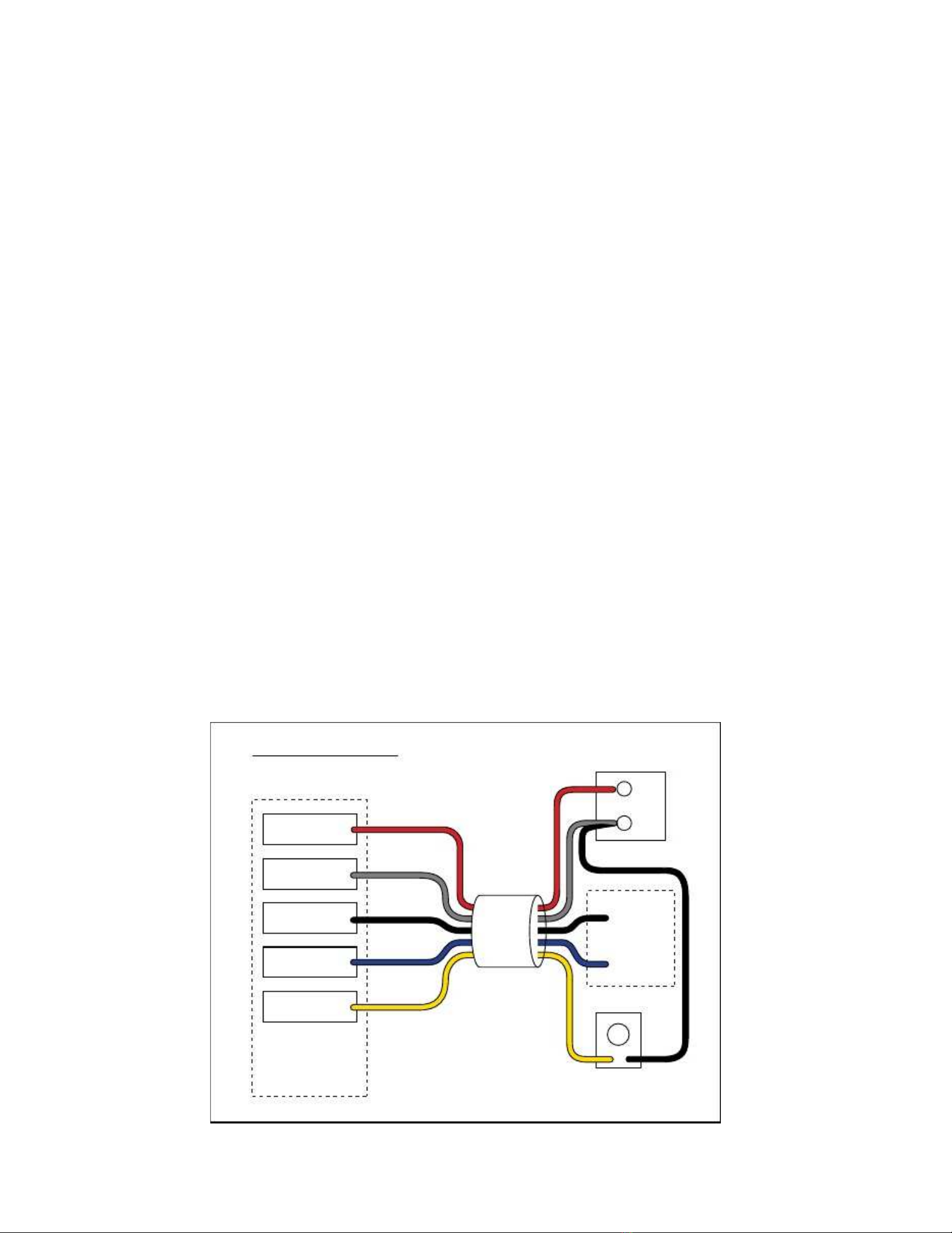
Installation Overview: Installation Overview:
------------------------------------------------------------page ------------------------------------------------------------page
22
Installing the VEHICLE SENSORInstalling the VEHICLE SENSOR
-----------------------------------------------page 3-----------------------------------------------page 3
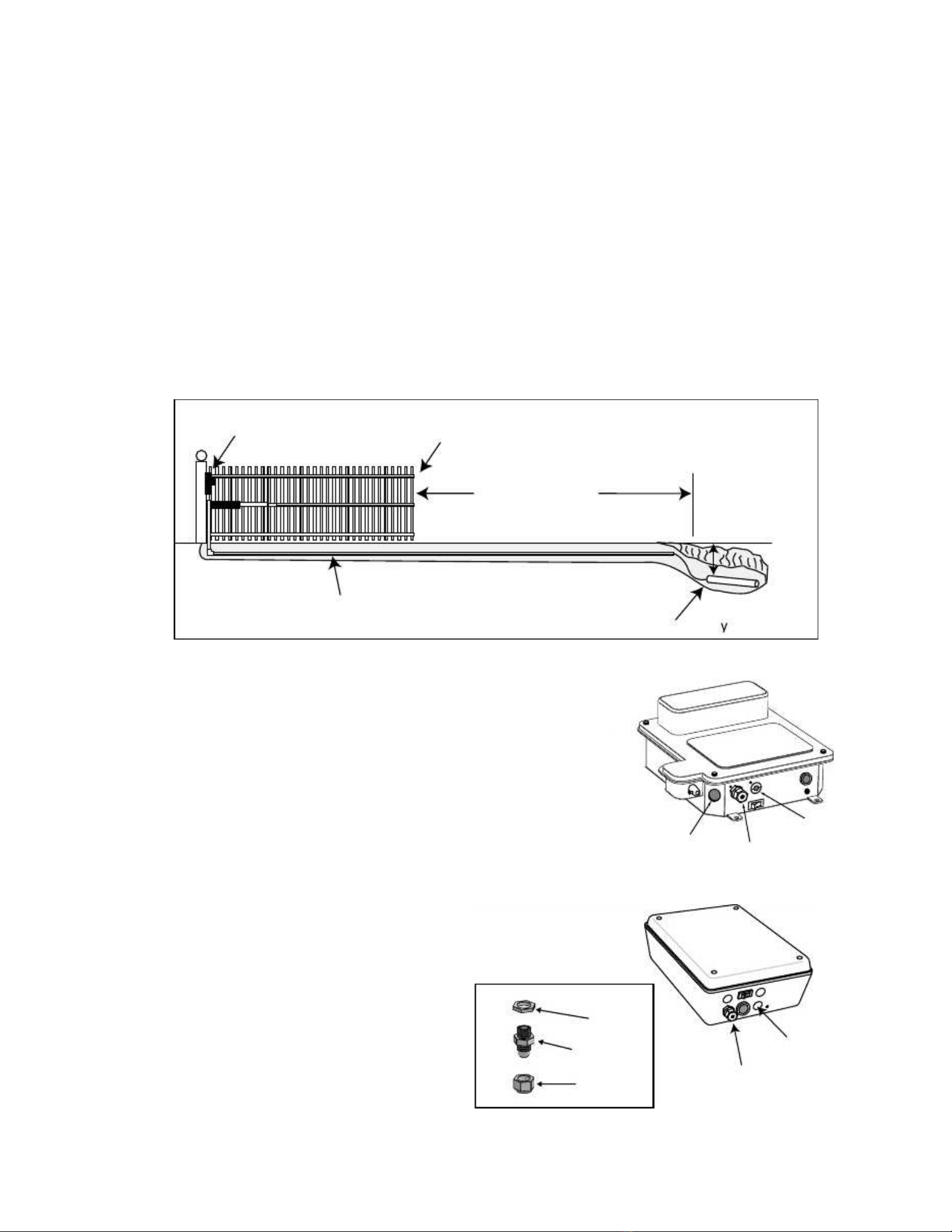
Determining SENSOR Location: Determining SENSOR Location:
-----------------------------------------------page -----------------------------------------------page
33
Installing The WIRE Installing The WIRE
CLAMP: CLAMP:
--------------------------------------------------page --------------------------------------------------page
33
Wiring the SENSOR to Wiring the SENSOR to
the Mighty Mule the Mighty Mule
Opener: Opener:
--------------------------------------------------------
page 4page 4
Accessory TermiAccessory Termi
nal Connection ------------------------------------------------page nal Connection ------------------------------------------------page
44
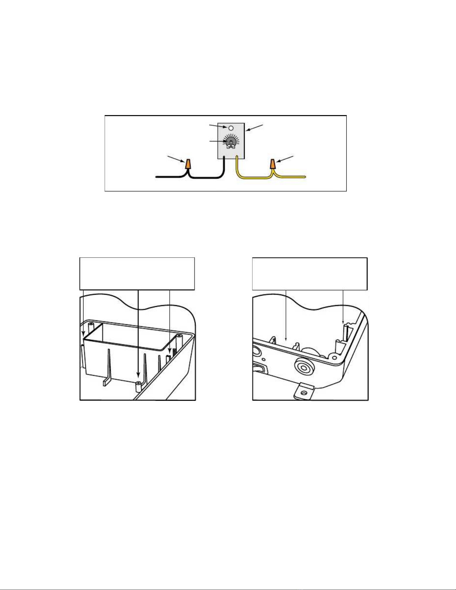
Connecting the Range AdjustmConnecting the Range Adjustm
ent Control Board: ent Control Board:
--------------------------page 5--------------------------page 5
Power Supply ConnectionPower Supply Connection
: ------------------------------------------------------: ------------------------------------------------------
page 5page 5
Powering Powering
up the SENup the SEN
SOR: SOR:
-----------------------------------------------------page 6-----------------------------------------------------page 6
Adjusting Adjusting
the Range: the Range:
------------------------------------------------------------page 6------------------------------------------------------------page 6
Saety Precautions: ---------------------------------------------------------------page 6Saety Precautions: ---------------------------------------------------------------page 6
Installation on other Brand Gate OpenersInstallation on other Brand Gate Openers
--------------------------------------page 7--------------------------------------page 7
TT
echnical echnical
SpecifcationsSpecifcations
-------------------------------------------------------------page 8-------------------------------------------------------------page 8
TT
rouble Shoorouble Shoo
tingting
---------------------------------------------------------------------page 8---------------------------------------------------------------------page 8
Other GTO ProductsOther GTO Products
----------------------------------------------------------------page 9----------------------------------------------------------------page 9
Metric Conversion Chart & WarrantyMetric Conversion Chart & Warranty
----------------------------------------------------------
Inside Inside
Back Back
CoverCover
Joe KelleJoe Kelle
y,y,
President of GTO, Inc.President of GTO, Inc.
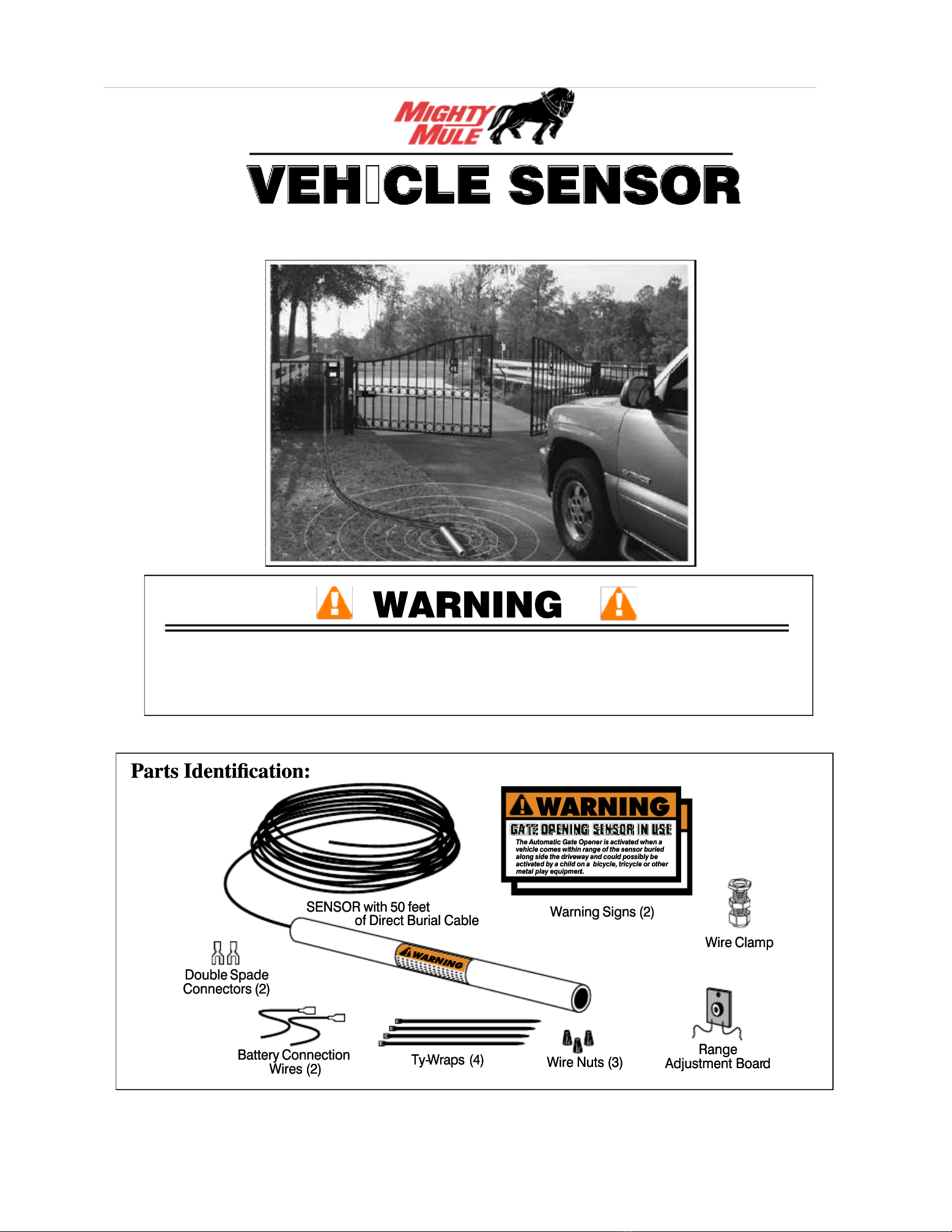
or purchasing the hands reeor purchasing the hands ree
VEHICLE SENSORVEHICLE SENSOR
. .
This product requires nThis product requires n
o maintenance and will go maintenance and will g
ive youive you
years o enjoyment by providinyears o enjoyment by providin
g hands ree operation o your gate. g hands ree operation o your gate.
GTO, Inc., has been designing and manuac-GTO, Inc., has been designing and manuac-
turing reliable, high quality productturing reliable, high quality product
s since 1987. s since 1987.
Our corporate headquarters and state o the art manuacturingOur corporate headquarters and state o the art manuacturing
acility is located in Tacility is located in T
allahassee, Florida. allahassee, Florida.
One o our highest priorities is to provide outstOne o our highest priorities is to provide outst
anding technical serviceanding technical service
to our customers. to our customers.
Thereore, i you have any questionThereore, i you have any question
s or require any technical assistance, visit wwws or require any technical assistance, visit www
.mighty-.mighty-
mule.com or call our toll ree mule.com or call our toll ree
line 800-543-1236 or technical support.line 800-543-1236 or technical support.
The VEHICLE SENSOR you have purchased is The VEHICLE SENSOR you have purchased is
designed with some o designed with some o
the most advanced technology available.the most advanced technology available.
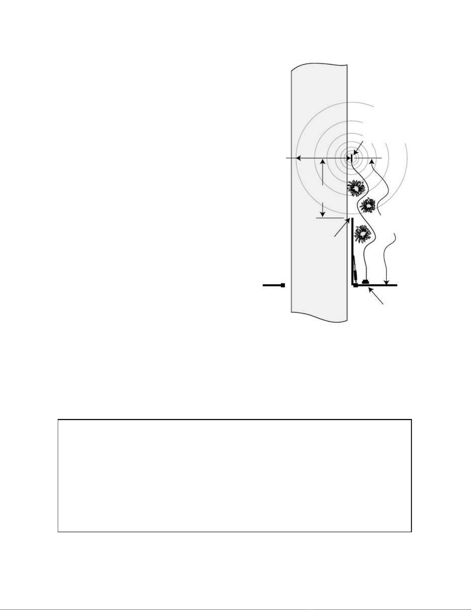
In layman’s terms, the sensor detects a change in the In layman’s terms, the sensor detects a change in the
earths magnetic eld caused by a earths magnetic eld caused by a
mass o metal in motionmass o metal in motion
and automatically opens your gate. and automatically opens your gate.
The range adjustment potentiThe range adjustment potenti
ometer (POT) that connects to the controometer (POT) that connects to the contro
l boxl box
provides you with the ability provides you with the ability
to increase or to increase or
decrease the sensor’s sensitivitdecrease the sensor’s sensitivit
y range.y range.
I a metal object I a metal object
is placed directly above the sensor (with little motion) it may cause the is placed directly above the sensor (with little motion) it may cause the
sensor to activate, thussensor to activate, thus
opening your gate. opening your gate.
For this reason we do not recommend the For this reason we do not recommend the
VEHICLE SENSOR in enviroVEHICLE SENSOR in enviro
nments exposed tonments exposed to
children.children.
Prior to installing your Sensor please read the manual thoroughlPrior to installing your Sensor please read the manual thoroughl
yy
. .
There are important saety recommendatiThere are important saety recommendati
onsons
o which you should be aware. o which you should be aware.
This product, and any accessory you purchase, shouThis product, and any accessory you purchase, shou
ld only be installed on a gateld only be installed on a gate
opener that meets the current saety standard (UL325). opener that meets the current saety standard (UL325).
I you have a gate opener that is not listed with the currentI you have a gate opener that is not listed with the current
standards, please contact the GTO sales department at 800-543-4283 or 850-575-0176 or consultation on a gatestandards, please contact the GTO sales department at 800-543-4283 or 850-575-0176 or consultation on a gate
opener that can meet your opener that can meet your
specic needs.specic needs.
Thank You ...Thank You ...

Converting Metric Units to English EquivalentsConverting Metric Units to English Equivalents
When When
YY
ou ou
Know Know
Multiply Multiply
By By
TT
o o
Find Find
SymboSymbo
ll
centimeters centimeters
0.3937 0.3937
inches inches
in. in.
(or (or
“)“)
meters meters
3.2808 3.2808
eet eet
t. t.
(or (or
‘)‘)
kilograms kilograms
2.2046 2.2046
pounds pounds
lb. lb.
(or (or
#)#)
Converting English Units to Metric EquivalentsConverting English Units to Metric Equivalents
When When
YY
ou ou
Know Know
Multiply Multiply
By By
TT
o o
Find Find
SymboSymbo
ll
inches inches
2.5400 2.5400
centimeters centimeters
cmcm
eet eet
0.3048 0.3048
meters meters
mm
pounds pounds
0.4535 0.4535
kilograms kilograms
kgkg
Converting Converting
TT
emperatureemperature
deg. deg.
Celsius Celsius
(ºC (ºC
x x
1.8) 1.8)
+ +
32 32
deg. deg.
Fahrenheit Fahrenheit
ºFºF
deg. deg.
Fahrenheit Fahrenheit
(ºF-32) (ºF-32)
÷ ÷
1.8 1.8
deg. deg.
Celsius Celsius
ºCºC
Conversion ChartConversion Chart
This product and any accessory you purchase should only be installed on a gateThis product and any accessory you purchase should only be installed on a gate
opener that meets the opener that meets the
current saety standard, UL325, 4th Edition. current saety standard, UL325, 4th Edition.
I you havI you hav
ee
a gate opener that is not listed with the current standard please contact the GTOa gate opener that is not listed with the current standard please contact the GTO
sales department or consultation on a gate opener that can meet your specicsales department or consultation on a gate opener that can meet your specic
needs.needs.
GTOGTO
Limited One Year Warranty:Limited One Year Warranty:
GTO, Inc., gate openers and GTO, Inc., gate openers and
accessories are warranted by accessories are warranted by
the manuacturer against deects in materials athe manuacturer against deects in materials a
nd manuacturer workmanship ornd manuacturer workmanship or
a period o one (1) year rom date a period o one (1) year rom date
o purchase,o purchase,
provided the recommended installation proprovided the recommended installation pro
cedures have been followcedures have been follow
ed.ed.
In the case In the case
o product ailure due to deective material or o product ailure due to deective material or
manuacturer workmanship within the one (1) year warranty period, the manuacturer workmanship within the one (1) year warranty period, the
productproduct
will be repaired or replaced will be repaired or replaced
(at the manuacturer’s option) at no charge to the (at the manuacturer’s option) at no charge to the
customer, i returned reight prepaid to GTO, Inc., 3121customer, i returned reight prepaid to GTO, Inc., 3121
Hartseld Road, Tallahassee, Florida, USA 32303.Hartseld Road, Tallahassee, Florida, USA 32303.
IMPORTANT: Call (800) 543-1236 or aIMPORTANT: Call (800) 543-1236 or a
Return Goods Authorization (RGA) num-Return Goods Authorization (RGA) num-
ber beore returning accessory to actory.ber beore returning accessory to actory.
Products received at thProducts received at th
e actory without an RGA numbe actory without an RGA numb
er will not be accepted. er will not be accepted.
ReplacementReplacement
or repaired parts are covered by this warranty or theor repaired parts are covered by this warranty or the
remainderremainder
o the one (1) o the one (1)
year warranty period or six (6) year warranty period or six (6)
months, whichever is greater.months, whichever is greater.
GTO, GTO,
Inc. will pay the shipping charges (equal to United Parcel Service GROUND rate) or return to the owner o items repaired underInc. will pay the shipping charges (equal to United Parcel Service GROUND rate) or return to the owner o items repaired under
warranty.warranty.
The manuacturer will not be The manuacturer will not be
responsible or any charges or damages responsible or any charges or damages
incurred in the removal o the incurred in the removal o the
deective parts or repair, or or thedeective parts or repair, or or the
reinstallation o those parts ater repair. This warranty shall be considered void i reinstallation o those parts ater repair. This warranty shall be considered void i
damage to the damage to the
product(s) was due to improper installationproduct(s) was due to improper installation
or use, connection to an improper power source, or i damage was caused by lightning, wind, re, food, insects or other natural agent.or use, connection to an improper power source, or i damage was caused by lightning, wind, re, food, insects or other natural agent.
Ater the one (1) year warranty perioAter the one (1) year warranty perio
d, GTO, Inc. d, GTO, Inc.
will make any necessary repairs or a nominal will make any necessary repairs or a nominal
ee. ee.
Call GTO at (800) 543-1Call GTO at (800) 543-1
236 or236 or
more inormation. more inormation.
This warranty gives you specic legal rights, and you may also have other rights which may vary rom state to state.This warranty gives you specic legal rights, and you may also have other rights which may vary rom state to state.
This warranty is in lieu This warranty is in lieu
o all other warranties, expressed or o all other warranties, expressed or
implied.implied.
NOTE: Verifcation o the warranty period requires copies oNOTE: Verifcation o the warranty period requires copies o
receipts or other proo receipts or other proo
o purchase. o purchase.
Please retain these records.Please retain these records.

11
Beore YBeore Y
ou ou
StarStar
t t
......
TT
erms and erms and
Defnitions:Defnitions:
• •
METMET
AL OBJECT: AL OBJECT:
anything that is anything that is
made o made o
iron-baseiron-base
d metal, d metal,
rom a rom a
child’s child’s
toy to toy to
a car a car
or truck.or truck.
• •
SENSOR: the SENSOR: the
magnetic magnetic
device device
inside thinside th
e waterprooe waterproo
tube tube
that detects that detects
METMET
AL OBJECTS AL OBJECTS
in motiin moti
on.on.
• •
MAGNMAGN
ETIC FIELDETIC FIELD
: an : an
area around area around
the SENthe SEN
SOR where SOR where
metal imetal i
n motn mot
ion can ion can
be detectbe detect
ed.ed.
• •
MAGNMAGN
ETIC DISTURBETIC DISTURB
ANCE: a ANCE: a
change in change in
the MAthe MA
GNETIC FIELD GNETIC FIELD
which letwhich let
s the s the
SENSOR knoSENSOR kno
w that w that
itit
needs to send a signal to the gate opener to open the gate.needs to send a signal to the gate opener to open the gate.
• •
RANGE: thRANGE: th
e distance e distance
rom the rom the
SENSOR in SENSOR in
which a which a
MAGNEMAGNE
TIC DISTURBTIC DISTURB
ANCE can ANCE can
be detected be detected
in thein the
MAGNETIC FIELD.MAGNETIC FIELD.
• •
RANGE RANGE
ADJUSTMENTADJUSTMENT
: the RANG: the RANG
E is adjE is adj
ustable rom ustable rom
a 3 to a 3 to
12 oot* 12 oot*
radius by radius by
tuning thtuning th
e e
ADJUSTMENTADJUSTMENT
POTENTIOMETER (POT) on the RANGE ADJUSTMENT CONTROL BOARD (shown on page 5). WithinPOTENTIOMETER (POT) on the RANGE ADJUSTMENT CONTROL BOARD (shown on page 5). Within
this RANGE, the closer you get to the SENSOR, the less metal and motion an object needs to cause a DIS-this RANGE, the closer you get to the SENSOR, the less metal and motion an object needs to cause a DIS-
TURBANCE in the MAGNETIC FIELD.TURBANCE in the MAGNETIC FIELD.
CAUTIONCAUTION
This principle explains why a child’s tricycle, bicycle and other This principle explains why a child’s tricycle, bicycle and other
metal objects moving close to themetal objects moving close to the
SENSOR may have the same DISTURBANCE as a car SENSOR may have the same DISTURBANCE as a car
or truck at a or truck at a
greater distance, and can cause greater distance, and can cause
the gatethe gate
to open.to open.
• •
WIRE CLAMP: WIRE CLAMP:
a dea de
vice which vice which
provides provides
a secure a secure
and weatherpand weatherp
roo openinroo openin
g or g or
the cable the cable
rom the rom the
SENSORSENSOR
to be brought into a control box to be brought into a control box
(see Parts Identication on cover).(see Parts Identication on cover).
• •
DOUBLE SPDOUBLE SP
ADE CONNADE CONN
ECTOR: ECTOR:
a wire a wire
connector wconnector w
hich allohich allo
ws the ws the
connection connection
o two o two
wires to wires to
be connect-be connect-
ed to a single terminal (see ed to a single terminal (see
Parts Identication on cover).Parts Identication on cover).
How the VEHICLE SENSOR works:How the VEHICLE SENSOR works:
• •
When a mWhen a m
etal object etal object
such as a such as a
car, trucar, tru
ck or mock or mo
torcycle in torcycle in
motion dmotion d
isturbs the isturbs the
MAGNEMAGNE
TIC FIELD aroTIC FIELD aro
und theund the
SENSOR, a signal is sent SENSOR, a signal is sent
to the automatic gate opener’s control board, signaling it to open the gate.to the automatic gate opener’s control board, signaling it to open the gate.
• •
The metal The metal
object musobject mus
t be in t be in
motion to motion to
disturb thdisturb th
e MAe MA
GNETIC FIELD, GNETIC FIELD,
thus actithus acti
vating vating
the gate the gate
openeropener
..
How the VEHICLE SENSOR’s RANGE ADJUSTMENT worksHow the VEHICLE SENSOR’s RANGE ADJUSTMENT works
::
• •
The RANThe RAN
GE disGE dis
tance can tance can
be adjbe adj
usted rousted ro
m a m a
3 to 3 to
12 oo12 oo
t* radiut* radiu
s rom s rom
the SENthe SEN
SOR.SOR.
• •
The potenThe poten
tiometer vtiometer v
aries the aries the
sensitivisensitivi
ty range ty range
o the o the
SENSOR to SENSOR to
avoid avoid
unwanted unwanted
moving moving
metal obmetal ob
jects romjects rom
activatactivat
ing the gate ing the gate
opener, such as: other moving gates; metal opener, such as: other moving gates; metal
play equipment; garage doors; other play equipment; garage doors; other
vehicularvehicular
trac; etc.trac; etc.
• •
With With
the RANGE the RANGE
adjusted to adjusted to
the maximthe maxim
um o 1um o 1
2 eet*, a 2 eet*, a
large metal large metal
object moobject mo
ving sloving slo
wly will wly will
be detectedbe detected
12 eet* rom the SENSOR, 12 eet* rom the SENSOR,
while a small metal object moving slowly might not be detected at the samewhile a small metal object moving slowly might not be detected at the same
distance. As you movdistance. As you mov
e closer toward the SENSOR, the small moving metal object will at some point cause e closer toward the SENSOR, the small moving metal object will at some point cause
aa
DISTURBANCE in the MAGNETIC FIELD and activate the gate opener.DISTURBANCE in the MAGNETIC FIELD and activate the gate opener.
Placement o the SENSOR:Placement o the SENSOR:
Please read the instructions Please read the instructions
completely beore ycompletely beore y
ou begin the ou begin the
installation.installation.
**
Range diRange di
stance is astance is a
pprppr
oximate aoximate a
nd will vand will va
ry due to oury due to ou
tside inttside int
erfererfer
ence, type of ence, type of
soil, vehicsoil, vehic
le mass, sple mass, sp
eed, etc.eed, etc.

22
• •
The The
SENSOR SENSOR
comes comes
with with
50 50
eet eet
o o
cable. cable.
A A
typi-typi-
cal installation will require about 5 eet o cal installation will require about 5 eet o
cablecable
to come rom the ground up to come rom the ground up
and into the controland into the control
box or connection to the power supply and controlbox or connection to the power supply and control
board. Check your specic installation or exactboard. Check your specic installation or exact
dimensions.dimensions.
• •
From From
the the
point point
on on
the the
ground ground
where where
you you
will will
runrun
the Sensor cable into the control box, the Sensor cable into the control box,
lay the cablelay the cable
out on a path as ar as you can rom the control box.out on a path as ar as you can rom the control box.
The SENSOR should be no more than 2 eet romThe SENSOR should be no more than 2 eet rom
the edge o the the edge o the
drivedrive
way and no closer than 25 way and no closer than 25
eeteet
rom the end o the open gate.rom the end o the open gate.
• •
The The
SENSOR’s SENSOR’s
RANGE RANGE
can can
be be
adjusted adjusted
to to
aa
maximum o 12 eet*. The movement o a gate inmaximum o 12 eet*. The movement o a gate in
the open position could cause a DISTURBANCE inthe open position could cause a DISTURBANCE in
the MAGNETIC FIELD o the SENSOR i it comesthe MAGNETIC FIELD o the SENSOR i it comes
within the RANGE o the SENSOR. within the RANGE o the SENSOR.
Make sure theMake sure the
end o the open gate is a miend o the open gate is a mi
nimum o nimum o
25 eet rom25 eet rom
the SENSOR. I you the SENSOR. I you
have a situation where thehave a situation where the
SENSOR has to be SENSOR has to be
buried closer than 25 eet youburied closer than 25 eet you
will need to adjust the RANGE o the SENSOR towill need to adjust the RANGE o the SENSOR to
compensate or the closeness.compensate or the closeness.
• •
The The
SENSOR SENSOR
must must
be be
buried buried
12” 12”
in in
soil soil
to to
preventprevent
direct sunlight rom causing overheating. This alsodirect sunlight rom causing overheating. This also
prevents large animals rom activating the sensorprevents large animals rom activating the sensor
due to physical vibrations.due to physical vibrations.
For Optimum Perormance:For Optimum Perormance:
• •
Locate the SENSOR as ar as possible away rom power transoLocate the SENSOR as ar as possible away rom power transo
rmers, power lines, undergrormers, power lines, undergro
und gasund gas
line, and telephone lines.line, and telephone lines.
• •
Locate the SENSOR away rom general movinLocate the SENSOR away rom general movin
g trac to prevent unwanted actig trac to prevent unwanted acti
vation. Remembervation. Remember
that the SENSOR detects MAGNETIC DISTURBANCES caused by a vehicle’s mass and velocity.that the SENSOR detects MAGNETIC DISTURBANCES caused by a vehicle’s mass and velocity.
• •
It is recommended that yIt is recommended that y
ou run the Sensor cable insiou run the Sensor cable insi
de PVC conduit.de PVC conduit.
• •
Do not run Sensor cable in conduit with other wires such as ADo not run Sensor cable in conduit with other wires such as A
C power or other control wires.C power or other control wires.
• •
The SensoThe Senso
r cabler cable
CANNOTCANNOT
be spliced. I you need be spliced. I you need
more wire, contact the GTO Sales Departmentmore wire, contact the GTO Sales Department
at 1-800-543-GATE (4283).at 1-800-543-GATE (4283).
Installation OverviewInstallation Overview
::
• •
Once the Once the
best locatbest locat
ion or ion or
the SENSOR the SENSOR
is determiis determi
ned, you ned, you
are ready are ready
to bto b
ury the ury the
SENSOR and SENSOR and
run the run the
cablecable
underground to the control box. underground to the control box.
Connect the SENSOR Connect the SENSOR
wires and the wires and the
RANGE ADJUSTMRANGE ADJUSTM
ENT CONTROLENT CONTROL
BOARD to the gate opener control board and power supply. Adjust the RANGE i necessary. Finally, placeBOARD to the gate opener control board and power supply. Adjust the RANGE i necessary. Finally, place
the WARNING signs on the gate. That’s it!the WARNING signs on the gate. That’s it!
Gate OpenerGate Opener
Control BoxControl Box
DrivewayDriveway
RANGE:RANGE:
12 ft. radius12 ft. radius
(max)(max)
45 ft. of45 ft. of
Cable (max)Cable (max)
SENSOR:SENSOR:
2 feet from2 feet from
driveway (max)driveway (max)
and 12” deepand 12” deep
Open GateOpen Gate
OutsideOutside
Sensor RangeSensor Range
25 ft. from25 ft. from
gate (min)gate (min)
(Allow 5 ft for wiring(Allow 5 ft for wiring
to Control Box)to Control Box)
**
Range diRange di
stance is astance is a
pprppr
oximate aoximate a
nd will vand will va
ry due to oury due to ou
tside inttside int
erfererfer
ence, type of ence, type of
soil, vehicsoil, vehic
le mass, sple mass, sp
eed, etc.eed, etc.

33
Step 1:Step 1:
Determine the optimum location or the VEHICLE SENSOR Determine the optimum location or the VEHICLE SENSOR
using the inormation ound in using the inormation ound in
“Placement“Placement
o the SENSOR” on o the SENSOR” on
page 2. Then dig a page 2. Then dig a
hole approximately 12 inches deep and 24 inches long within 2 hole approximately 12 inches deep and 24 inches long within 2
eet andeet and
parallel to the edge o parallel to the edge o
the drivethe drive
wayway
. Next, dig a . Next, dig a
trench approximately 12 inches deep rom this hole to a trench approximately 12 inches deep rom this hole to a
spot un-spot un-
der the gate opener control box to run the cable rom the SENSOR to the control board.der the gate opener control box to run the cable rom the SENSOR to the control board.
Keep the SENSOR and the cable Keep the SENSOR and the cable
uncovered at this time, but out o direct sunlight.uncovered at this time, but out o direct sunlight.
WW
e recommend that the cable be e recommend that the cable be
run in PVC conduit to the run in PVC conduit to the
control box to prevent damage to the cable rom lawncontrol box to prevent damage to the cable rom lawn
mowers, weed eaters and grazing animals.mowers, weed eaters and grazing animals.
Step 4:Step 4:
Unscrew and remove the lock nut rom theUnscrew and remove the lock nut rom the
WIRE CLAMP hub (WIRE CLAMP hub (
included with hardwareincluded with hardware
). From). From
the outside o the control box, insert the WIRE CLAMPthe outside o the control box, insert the WIRE CLAMP
hub and sealing nut (hub and sealing nut (
see illustration rightsee illustration right
) into the) into the
newnew
WIRE CLAMP holeWIRE CLAMP hole
. Finger tighten the lock . Finger tighten the lock
nut ontonut onto
the threaded end o the WIRE the threaded end o the WIRE
CLAMP hub rom insideCLAMP hub rom inside
the box.the box.
Installing The WIRE CLAMP:Installing The WIRE CLAMP:
The WIRE CLAMP (includ-The WIRE CLAMP (includ-
ed) is used to secure the sensor cable where it enters the control box toed) is used to secure the sensor cable where it enters the control box to
prevent it rom being accidently pulled out.prevent it rom being accidently pulled out.
Step 2:Step 2:
I you are installing the SENSOR on I you are installing the SENSOR on
a Mighty Mulea Mighty Mule
FM700, FM500 and the FM502 gate openers, use FM700, FM500 and the FM502 gate openers, use
a screwdriver or steela screwdriver or steel
punch to careully remove the thin plastic knockout disk (punch to careully remove the thin plastic knockout disk (
see illustra-see illustra-
tions at righttions at right
) at the ) at the
bottom o the control box. I you bottom o the control box. I you
have a FM702have a FM702
dual gate opener system, drill a 7/8” dual gate opener system, drill a 7/8”
diameter hole at the bottom o thediameter hole at the bottom o the
control box and install the WIRE CLAMP.control box and install the WIRE CLAMP.
Step 3:Step 3:
Use a sharp knie or Use a sharp knie or
deburring tool to clean the rough edgesdeburring tool to clean the rough edges
rom rom
the the
hole.hole.
Be careul with tools to avoid contact or damage to the controlBe careul with tools to avoid contact or damage to the control
board!board!
Knockout DiskKnockout Disk
WIRE CLAMP forWIRE CLAMP for
Opener Power CordOpener Power Cord
Mighty Mule FM700 & FM702Mighty Mule FM700 & FM702
Control BoxControl Box
Drill 7/8" diameterDrill 7/8" diameter
hole for Dual Gatehole for Dual Gate
SystemSystem
Determining SENSOR Location:Determining SENSOR Location:
IMPORTIMPORT
ANTANT
: Clear an area 20 feet in all directions of metal tools, toys and automobiles,: Clear an area 20 feet in all directions of metal tools, toys and automobiles,
to prevent magnetic disturbance during testing and installation.to prevent magnetic disturbance during testing and installation.
InstallInstall
ing the Ving the V
ehicle ehicle
Sensor .Sensor .
....
Gate openerGate opener
control boxcontrol box
DrivewayDriveway
12”12”
Minimum of 25 feetMinimum of 25 feet
SENSOR: 2 feet from drivewaSENSOR: 2 feet from drivewa
Open gate outsideOpen gate outside
sensor rangesensor range
PVC conduit in ground andPVC conduit in ground and
up to control box recommendedup to control box recommended
Knockout DiskKnockout Disk
WIRE CLAMP forWIRE CLAMP for
Opener Power CordOpener Power Cord
Mighty Mule FM500 & FM502Mighty Mule FM500 & FM502
Control BoxControl Box
Sealing NutSealing Nut
HubHub
Lock NutLock Nut
WW
ii
rr
ee
CC
ll
aa
mm
pp

44
IMPORTANT:IMPORTANT:
TURN OFF theTURN OFF the
power and dis-power and dis-
connect the battery wires bconnect the battery wires b
eore you begin to connecteore you begin to connect
the SENSOR wires to any gate the SENSOR wires to any gate
openeropener
..
Step 5:Step 5:
Run the cable rom the Run the cable rom the
SENSOR through aSENSOR through a
WIRE CLAMP into the control box. Pull about 8 - 10WIRE CLAMP into the control box. Pull about 8 - 10
inches o cable into the inches o cable into the
control box to reach the AC-control box to reach the AC-
CESSORY TERMINAL BLOCK and BATTERY TER-CESSORY TERMINAL BLOCK and BATTERY TER-
MINALS in the control box. MINALS in the control box.
Now tighten the WIRENow tighten the WIRE
CLAMP nut to CLAMP nut to
secure the cable secure the cable
in the WIRE CLAMPin the WIRE CLAMP
..
Step 6:Step 6:
Strip about 3/8 o an inch Strip about 3/8 o an inch
o insulation rom theo insulation rom the
YELLOW, BLACK, RED and BLUE wires in the SEN-YELLOW, BLACK, RED and BLUE wires in the SEN-
SOR CABLE.SOR CABLE.
Wiring the SENSOR to Mighty Mule Gate Openers:Wiring the SENSOR to Mighty Mule Gate Openers:
NOTE:NOTE:
The SHIELD is the braided metalThe SHIELD is the braided metal
wire wrapped around the insulated leadswire wrapped around the insulated leads
inside the SENSOR CABLE.inside the SENSOR CABLE.
PVC ConduitPVC Conduit
WIRE CLAMP in KnockoutWIRE CLAMP in Knockout
Bottom of Control BoxBottom of Control Box
CABLE fromCABLE from
the Opening Sensorthe Opening Sensor
OO
NN
ALARM ALARM
ACCESSORACCESSOR
Y Y
RCVRRCVR
SEQ1SEQ1
SEQ2SEQ2
LEARNLEARN
BB
LL
UU
OO
RR
GG
WW
HH
TT
GG
RR
NN
R R
B B
GG
ConnectConnect
BLUEBLUE
wire from thewire from the
SENSOR CABLESENSOR CABLE
to theto the
BLUBLU
terminal on the openerterminal on the opener
control board.control board.
Connect theConnect the
BLACKBLACK
wirewire
from thefrom the
SENSOSENSO
RR
CABLCABL
EE
toto
thethe
GRNGRN
terminal on theterminal on the
opener control board.opener control board.
PRO-1000, PRO-SL1000 and Old Mighty MulePRO-1000, PRO-SL1000 and Old Mighty Mule
Control BoardsControl Boards
BLUEBLUE
BLACKBLACK
G RG R
N N
B L K B L K
R ER E
DD
RECEIVERRECEIVER
C OM C OMC O M C OM
CC
YY
CC
LL
EE
CC
LL
OO
SS
EE
SS
AA
FF
EE
TT
YY
EE
XX
II
TT
OO
PP
EE
NN
SS
HH
AA
DD
OO
WW
LL
OO
OO
PP
CC
LL
OO
SS
EE
EE
DD
GG
EE
OO
PP
EE
NN
EE
DD
GG
EE
J11J11
J8J8
J12J12
GTO/PRO DC Powered PRO-SW3000GTO/PRO DC Powered PRO-SW3000
and PRO-SW4000 Control Boardsand PRO-SW4000 Control Boards
Connect theConnect the
BLUEBLUE
wire fromwire from
thethe
SENSOSENSO
RR
CABLECABLE
to theto the
EXIT/OPENEXIT/OPEN
terminal on theterminal on the
opener control board.opener control board.
Connect theConnect the
BLACKBLACK
wire from thewire from the
SENSORSENSOR
CABLECABLE
to one of theto one of the
COMMONCOMMON
terminals onterminals on
the opener control board.the opener control board.
BLUEBLUE
BLACKBLACK
RECRRECR
GG
RR
NN
BB
LL
KK
RR
EE
DD
EE
XX
II
TT
SS
AA
FF
EE
TT
YY
EE
DD
GG
EE
CC
YY
CC
LL
EE
CC
OO
MM
MM
OO
NN
LINKLINK
Mighty Mule 350 Control BoardMighty Mule 350 Control Board
Connect theConnect the
BLUEBLUE
wire fromwire from
thethe
SENSOSENSO
RR
CABLCABL
EE
to theto the
EXITEXIT
terminal on the openerterminal on the opener
control board.control board.
Connect theConnect the
BLACKBLACK
wire fromwire from
thethe
SENSOSENSO
RR
CABLCABL
EE
to one ofto one of
thethe
COMMONCOMMON
terminals on theterminals on the
opener control board.opener control board.
BLUEBLUE
BLACKBLACK
RECEIVERRECEIVER
COM C OMCOM COM
CC
YY
CC
LL
EE
CC
LL
OO
SS
EE
SS
AA
FF
EE
TT
YY
EE
XX
II
TT
//
OO
PP
EE
NN
SS
HH
AA
DD
OO
WW
LL
OO
OO
PP
CC
LL
OO
SS
EE
EE
DD
GG
EE
OO
PP
EE
NN
EE
DD
GG
EE
BLKBLK
GG
RR
N N
RR
EE
DD
Mighty Mule 500 & 502Mighty Mule 500 & 502
Control BoardsControl Boards
Connect theConnect the
BLUEBLUE
wire fromwire from
thethe
SENSOR CABLESENSOR CABLE
to theto the
EXIT/OPENEXIT/OPEN
terminal on theterminal on the
opener control board.opener control board.
Connect theConnect the
BLACKBLACK
wire from thewire from the
SENSORSENSOR
CABLECABLE
to one of theto one of the
COMMONCOMMON
terminals onterminals on
the opener control board.the opener control board.
BLUEBLUE
BLACKBLACK
RECEIVERRECEIVER
ALMALM
GTO RCVR.GTO RCVR.
CC
OO
MM
GG
RR
NN
BB
LL
KK
RR
EE
DD
CC
YY
CC
LL
EE
SS
AA
FF
EE
TT
YY
EE
XX
II
TT
SS
HH
AA
DD
OO
WW
OO
PP
EE
NN
EE
DD
GG
EE
CC
OO
MM
CONTROL INPUTSCONTROL INPUTS
CC
LL
OO
SS
EE
EE
DD
GG
EE
Connect theConnect the
BLUEBLUE
wire fromwire from
thethe
SENSOR CABLESENSOR CABLE
to theto the
EXITEXIT
terminal on the openerterminal on the opener
control board.control board.
Connect theConnect the
BLACKBLACK
wire fromwire from
thethe
SENSOR CABLESENSOR CABLE
to oneto one
of theof the
COMMONCOMMON
terminals onterminals on
the opener control board.the opener control board.
BLUEBLUE
BLACKBLACK
GEN-3 (Blue) Control BoardsGEN-3 (Blue) Control Boards
CC
OO
MM
CC
OO
MM
CC
OO
MM
GG
TT
OO
II
nn
cc
..
SS
XX
44
00
00
00
LL
CC
YY
CC
LL
EE
SS
AA
FF
EE
TT
YY
OO
PP
EE
NN
EE
DD
GG
EE
RR
UU
NN
22
OO
PP
EE
NN
CC
LL
OO
SS
EE
SS
TT
OO
PP
CC
OO
MM
CC
OO
MM
CC
OO
MM
SS
HH
AA
DD
OO
WW
LL
OO
OO
PP
Connect theConnect the
BLUEBLUE
wirewire
from thefrom the
SENSSENS
OROR
CABLECABLE
to theto the
OPENOPEN
terminal onterminal on
the opener control board.the opener control board.
Connect theConnect the
BLACKBLACK
wire fromwire from
thethe
SENSSENS
OROR
CABLECABLE
to oneto one
of theof the
COMMONCOMMON
terminals onterminals on
the opener control board.the opener control board.
BLUEBLUE
BLACKBLACK
GTO/PRO GP-SL100 and GP-SW100GTO/PRO GP-SL100 and GP-SW100
Control BoardsControl Boards

55
Connecting the Range Adjustment Control Board:Connecting the Range Adjustment Control Board:
Step 9:Step 9:
Connect the YELLOConnect the YELLO
W wire W wire
rom the rom the
SENSOR CABLE SENSOR CABLE
to the YELLOto the YELLO
W wire W wire
rom the rom the
Range AdjustmenRange Adjustmen
tt
control board using one o the WIRE NUTS provided.control board using one o the WIRE NUTS provided.
Step 10Step 10
: Connect the BLACK wire rom the Range Adjustment control board to the BLACK BATTERY: Connect the BLACK wire rom the Range Adjustment control board to the BLACK BATTERY
CONNECTOR wire (provided), along with the SHIELD wire rom the SENSOR CCONNECTOR wire (provided), along with the SHIELD wire rom the SENSOR C
ABLE (see Step 13 below).ABLE (see Step 13 below).
Step 11Step 11
: Secure : Secure
the RANGE ADJUSTMENT CONTRthe RANGE ADJUSTMENT CONTR
OL BOARD inside the gate OL BOARD inside the gate
opener control box. Theopener control box. The
control box has slots on both sides o control box has slots on both sides o
the top battery compartment or extra control boards, or you the top battery compartment or extra control boards, or you
can use thecan use the
optional mounting hole.optional mounting hole.
IMPORTANT:IMPORTANT:
DO NOT let exposed wiring or components on the control board make contact with other exposedDO NOT let exposed wiring or components on the control board make contact with other exposed
wiring or components.wiring or components.
Potentiometer (POT)Potentiometer (POT)
Range AdjustmentRange Adjustment
Control BoardControl Board
Wire NutWire Nut
Wire NutWire Nut
Optional Mounting HoleOptional Mounting Hole
YELLOW wireYELLOW wire
from SENSOR Cablefrom SENSOR Cable
YELLOWYELLOW
BLACKBLACK
BLACK BATTERYBLACK BATTERY
CONNECTOR wire providedCONNECTOR wire provided
MM
II
N N
MM
AA
X X
Power supply connection:Power supply connection:
Step 12:Step 12:
Connect the RED and BLACK control board wires rom the Connect the RED and BLACK control board wires rom the
opener to the DOUBLE SPADEopener to the DOUBLE SPADE
CONNECTORS (provided) as shown on the next CONNECTORS (provided) as shown on the next
page.page.
Step 13:Step 13:
Using a WIRE NUTUsing a WIRE NUT
, connect the SHIELD wire , connect the SHIELD wire
rom the SENSOR CABLE (along with the rom the SENSOR CABLE (along with the
BLACKBLACK
wire rom the Range Adjustment board) to the BLACK BATTERY CONNECTION wire provided. Using thewire rom the Range Adjustment board) to the BLACK BATTERY CONNECTION wire provided. Using the
remaining WIRE NUT connect the RED wire rom the SENSOR CABLE to the RED BATTERY CONNECTIONremaining WIRE NUT connect the RED wire rom the SENSOR CABLE to the RED BATTERY CONNECTION
wire provided.wire provided.
Step 14:Step 14:
Connect these wires to the DOUBLE SPADE CONNECTORS as shown.Connect these wires to the DOUBLE SPADE CONNECTORS as shown.
IMPORTANT:IMPORTANT:
Be sure to connect both RED leads to theBe sure to connect both RED leads to the
samesame
DOUBLE SPADE CONNECTOR and bothDOUBLE SPADE CONNECTOR and both
BLACK leads to theBLACK leads to the
otherother
DOUBLE SPADE CONNECTOR.DOUBLE SPADE CONNECTOR.
You will connect the DOUBLE SPADEYou will connect the DOUBLE SPADE
CONNECTORS to the battery in the next step.CONNECTORS to the battery in the next step.
The Range Adjustment Control BoardThe Range Adjustment Control Board
can be mounted in slots on either side ofcan be mounted in slots on either side of
top battery compartmenttop battery compartment
OROR
the mount-the mount-
ing hole beneath battery compartment.ing hole beneath battery compartment.
Mighty Mule FM500 & FM502 Control BoxMighty Mule FM500 & FM502 Control Box
The Range Adjustment Control BoardThe Range Adjustment Control Board
can be mounted in the slot at the bottomcan be mounted in the slot at the bottom
OROR
the slot at the bottom right. Both arethe slot at the bottom right. Both are
located beneath the circuit board.located beneath the circuit board.
Mighty Mule FM700 & FM702 Control BoxMighty Mule FM700 & FM702 Control Box

66
SHIELD from SENSOR CableSHIELD from SENSOR Cable
BLACK wire from RangeBLACK wire from Range
Adjustment control boardAdjustment control board
RED wire from SENSOR CableRED wire from SENSOR Cable
BLACK Opener Battery WireBLACK Opener Battery Wire
BLACK BATTERY CONNECTION WireBLACK BATTERY CONNECTION Wire
with Spade Connector included with SENSORwith Spade Connector included with SENSOR
RED BATTERY CONNECTION WireRED BATTERY CONNECTION Wire
with Spade Connector included with SENSORwith Spade Connector included with SENSOR
Double Spade ConnectorsDouble Spade Connectors
included with SENSORincluded with SENSOR
RED Opener Battery WireRED Opener Battery Wire
Adjusting the Range:Adjusting the Range:
Step 16:Step 16:
TT
est the SENSOR to see est the SENSOR to see
i it is working properly and i i it is working properly and i
thethe
RANGE needs adjusting or RANGE needs adjusting or
optimum perormance.optimum perormance.
• Turn the potentiometer (POT) clockwise to increase range.• Turn the potentiometer (POT) clockwise to increase range.
• Turn the potentiometer (POT) counter-clockw• Turn the potentiometer (POT) counter-clockw
ise to decrease ise to decrease
range.range.
Replace the control box cover and cover the SENSOR and Replace the control box cover and cover the SENSOR and
cable.cable.
MM
II
N N
MM
AA
X X
Saety Saety
PrecautionPrecaution
s:s:
Step 17:Step 17:
Place the WARNING SIGNS on bothPlace the WARNING SIGNS on both
sides o the gate using Ty-wraps included.sides o the gate using Ty-wraps included.
!!
WARNINGWARNING
GATE OPENINGGATE OPENING
SENSOR IN USESENSOR IN USE
The Automatic Gate Opener is activated when aThe Automatic Gate Opener is activated when a
vehicle comes within range of the sensor buriedvehicle comes within range of the sensor buried
along side the driveway and could possibly bealong side the driveway and could possibly be
activated by a child on activated by a child on
a bicycle, tricycle or othera bicycle, tricycle or other
metal play equipmmetal play equipm
ent.ent.
..
..
REWWARN01REWWARN01
Powering Up the SENSOR:Powering Up the SENSOR:
IMPORTANT: When the SENSORIMPORTANT: When the SENSOR
is frst powered up it must be un-is frst powered up it must be un-
disturbed or 60 seconds to disturbed or 60 seconds to
perormperorm
the sel test the sel test
and calibrations. Beoreand calibrations. Beore
powering the SENSOR make surepowering the SENSOR make sure
there are no moving metal objects orthere are no moving metal objects or
moving vehicles within range o themoving vehicles within range o the
SENSOR.SENSOR.
Step 15:Step 15:
Connect the DOUBLE SPADE CON-Connect the DOUBLE SPADE CON-
NECTORS to the battery terminals (RED WIRES toNECTORS to the battery terminals (RED WIRES to
POSITIVE (+) battery POSITIVE (+) battery
terminal and BLACK WIRESterminal and BLACK WIRES
to NEGATIVE (–) battery terminal). Wait 60 seconds.to NEGATIVE (–) battery terminal). Wait 60 seconds.
Turn the opener on and test the SENSOR.Turn the opener on and test the SENSOR.
NOTE:NOTE:
I you have other accessories connected to yourI you have other accessories connected to your
battery with double spade connectors you may needbattery with double spade connectors you may need
to connect a double spade connector to to connect a double spade connector to
a double spadea double spade
connector in order toconnector in order to
connect all the acces-connect all the acces-
sories.sories.

77
TT
ypical Gate ypical Gate
Wiring Connection:Wiring Connection:
••
Reerence Leads:Reerence Leads:
oo
RED RED
=> =>
Input Input
VV
oltage oltage
(+)(+)
oo
SHIELD SHIELD
=> =>
Ground/Common Ground/Common
(–)(–)
oo
BLACK BLACK
=> =>
Relay’s Relay’s
CommonCommon
oo
BLUE BLUE
=> =>
Relay’Relay’
s s
Normally Normally
OpenOpen
oo
YELLOW YELLOW
=> =>
Remote Remote
SENSOR SENSOR
[Range [Range
adjustment adjustment
potentiometer potentiometer
(POT)](POT)]
••
Terminology Defnitions:Terminology Defnitions:
oo
‘FREE EXIT/ENTRY’ is dened as input terminals (2) ‘FREE EXIT/ENTRY’ is dened as input terminals (2)
that upon activation (momentarily connected together) willthat upon activation (momentarily connected together) will
cause the gate to run cause the gate to run
in the open direction only. Note: In most in the open direction only. Note: In most
gate openers, one o the gate openers, one o the
two terminals is the ‘COM-two terminals is the ‘COM-
MON/GND’.MON/GND’.
••
Power supply connection:Power supply connection:
oo
DC power supply: (11-36 Vdc)DC power supply: (11-36 Vdc)
ßß
Connect the positive (+) lead o the power supply to Connect the positive (+) lead o the power supply to
the RED wire.the RED wire.
ßß
Connect the negative (-) lead o the power supply to Connect the negative (-) lead o the power supply to
the SHIELD wire.the SHIELD wire.
oo
AC power supply: (8-26 Vac)AC power supply: (8-26 Vac)
ßß
Connect the power supply to the Connect the power supply to the
RED & SHIELD RED & SHIELD
wires. There is no polarity or AC power supply.wires. There is no polarity or AC power supply.
••
Relay output connection:Relay output connection:
oo
Connect the BLUE wConnect the BLUE w
ire rom the SENSOR ire rom the SENSOR
to the ‘FREE EXto the ‘FREE EX
IT/ENTRIT/ENTR
Y’ o the gate opener.Y’ o the gate opener.
oo
Connect the BLACK wire rom the Connect the BLACK wire rom the
SENSOR to the SENSOR to the
‘COMMON/GND’ o the gate opener‘COMMON/GND’ o the gate opener
..
••
Range (POT) board connection:Range (POT) board connection:
oo
Connect the YELLOW wire rom the SENConnect the YELLOW wire rom the SEN
SOR to SOR to
the YELLOthe YELLO
W wire rom W wire rom
the Range Adjustment Board.the Range Adjustment Board.
oo
Connect the BLACK wire rom the Connect the BLACK wire rom the
Range Adjustment Board to a negative input voltage.Range Adjustment Board to a negative input voltage.
oo
Turn the POT clockwise to increase range.Turn the POT clockwise to increase range.
oo
Turn the POT counter-clockwise to decrease range.Turn the POT counter-clockwise to decrease range.
For Installation on Other Brand Gate Openers ...For Installation on Other Brand Gate Openers ...
I you are using theI you are using the
VEHICLE SENSORVEHICLE SENSOR
on any other automatic gate opener brand, use the inorma-on any other automatic gate opener brand, use the inorma-
tion below or wiring the system. I you do not understand the instructions below, please call GTO’stion below or wiring the system. I you do not understand the instructions below, please call GTO’s
Technical Support at 1-800-543-1236.Technical Support at 1-800-543-1236.
InputInput
VoltagVoltag
e (+)e (+)
InputInput
VoltagVoltag
e (–)e (–)
Relay OutputRelay Output
CommonCommon
Relay OutputRelay Output
Normally OpenNormally Open
RangeRange
AdjustmentAdjustment
RangeRange
AdjustmentAdjustment
BoardBoard
Input VoltageInput Voltage
11 - 36 Vdc or11 - 36 Vdc or
8 - 26 Vac8 - 26 Vac
––
++
Free Exit/EntryFree Exit/Entry
ConnectionsConnections
SENSORSENSOR
REDRED
SHIELDSHIELD
BLACKBLACK
BB
LL
AA
CC
KK
BLUEBLUE
YELLOWYELLOW
YY
EE
LL
LL
OO
WW
Generic Wiring DiagramGeneric Wiring Diagram

88
TECHNICAL SPECIFICATIONS:TECHNICAL SPECIFICATIONS:
••
Power supply: 8-26 Vac/dc.Power supply: 8-26 Vac/dc.
••
Current consumption: 1.5 mA typical.Current consumption: 1.5 mA typical.
••
Relay rating: Latching Relay rating: Latching
relayrelay
..
Nominal Nominal
switching switching
capacitcapacit
y y
(resistive (resistive
load) load)
1 1
Amp Amp
30 30
Vdc, Vdc,
0.5 0.5
Amp Amp
125 125
VV
acac
Max. Max.
switching switching
power power
(resistive (resistive
load) load)
30 30
WW
att, att,
62.5 62.5
V V
AA
Max. Max.
switching switching
voltage voltage
110 110
Vdc, Vdc,
125 125
VV
acac
Max. Max.
switching switching
current current
1 1
AmpAmp
••
Relay Trip Time: 2 seconds.Relay Trip Time: 2 seconds.
••
Operating Temperature: -25Operating Temperature: -25
°°
F (-14F (-14
°°
C) to 125C) to 125
°°
F (69F (69
°°
C).C).
••
Dimensions: 1-3/4” (44.5 mm) diameter x 16.5” (42 cm) long.Dimensions: 1-3/4” (44.5 mm) diameter x 16.5” (42 cm) long.
••
Adjustable range: 3 -12 Adjustable range: 3 -12
eet typical installation.eet typical installation.
••
Very low power consumption, ideal or battery application.Very low power consumption, ideal or battery application.
Troubleshooting:Troubleshooting:
Make sure all connections are correct.Make sure all connections are correct.
I the SENSOR is not working:I the SENSOR is not working:
1. Make sure the Range Adjustment is set at maximum range.1. Make sure the Range Adjustment is set at maximum range.
2. Disconnect the power (battery) to the SENSOR.2. Disconnect the power (battery) to the SENSOR.
3. Reconnect the power to the SENSOR and make sure that no metal object or vehicle is moving3. Reconnect the power to the SENSOR and make sure that no metal object or vehicle is moving
around the SENSOR or 60 seconds while it is calibrating.around the SENSOR or 60 seconds while it is calibrating.
4. Test the SENSOR to veriy that it is working properly.4. Test the SENSOR to veriy that it is working properly.
5. Check that push/pull DIP switches on Control Board are set correctly.5. Check that push/pull DIP switches on Control Board are set correctly.

99
Other GTO Products or Your Saety and Convenience:Other GTO Products or Your Saety and Convenience:
Key Chain Two Button Transmitter (FM134)Key Chain Two Button Transmitter (FM134)
The Key Chain Mini Transmitter is a miniature version o theThe Key Chain Mini Transmitter is a miniature version o the
Mighty MuleMighty Mule
entry transmitterentry transmitter
and has the same adjustable code settings. Used or and has the same adjustable code settings. Used or
remote control o multiple separate gateremote control o multiple separate gate
operators, and/or garage door operator(s).operators, and/or garage door operator(s).
(battery included)(battery included)
Automatic Gate LockAutomatic Gate Lock
(FM143)(FM143)
AA
MUST or securing the gatMUST or securing the gat
e against orced entry or exe against orced entry or ex
it. it.
Solenoid driSolenoid dri
ven,ven,
plated steel bolt lock with a zinc plated steel bolt lock with a zinc
plated steel housing. Used with Mighty Muleplated steel housing. Used with Mighty Mule
systems or maximum stability and security. Comes with a systems or maximum stability and security. Comes with a
keyed manual release.keyed manual release.
Recommended or gates over 8 t. (2.4m) long. Ideal Recommended or gates over 8 t. (2.4m) long. Ideal
or animal enclosures or highor animal enclosures or high
wind areas.wind areas.
(Not compatible with (Not compatible with
FM250, MM-SL1000B/MM-SL2000B)FM250, MM-SL1000B/MM-SL2000B)
5 Watt Solar Panel5 Watt Solar Panel
(FM121)(FM121)
I your gate application is ar I your gate application is ar
away rom an Aaway rom an A
C power outlet, or greater than C power outlet, or greater than
1,000 t1,000 t
(304.8m), you can choose to power your Mighty Mule gate operator system with these(304.8m), you can choose to power your Mighty Mule gate operator system with these
high output Mighty Mule solar panels. Each solar panel comes with tubular steel support,high output Mighty Mule solar panels. Each solar panel comes with tubular steel support,
mounting clips, wire connectors, and 8 t o Low Voltage Wire (RB509).mounting clips, wire connectors, and 8 t o Low Voltage Wire (RB509).
11
22
ABCABC
33
DEFDEF
44
GHIGHI
55
JKLJKL
66
MNOMNO
77
PRSPRS
88
TUVTUV
99
WXYWXY
00
Digital Keypad (FM137)Digital Keypad (FM137)
This specially designed digital keypad can be easily installed as a wireless or This specially designed digital keypad can be easily installed as a wireless or
wiredwired
keypad. It can be programmed to use up keypad. It can be programmed to use up
to 25 dierent personal identication numberto 25 dierent personal identication number
(PIN) codes. This used in combination with the Mighty Mule automatic gate lock(PIN) codes. This used in combination with the Mighty Mule automatic gate lock
(see(see
automatic gate lock)automatic gate lock)
adds an additional layer o security or adds an additional layer o security or
your propertyyour property
..
Entry Entry
TT
ransmitterransmitter
(FM135)(FM135)
TheThe
Mighty MuleMighty Mule
entry transmitter includes a visor clip and has adjustable code settings.entry transmitter includes a visor clip and has adjustable code settings.
This is the standard transmitter included in every Mighty Mule gate opener kit.This is the standard transmitter included in every Mighty Mule gate opener kit.
(battery included)(battery included)
Push Button (Doorbell) ControlPush Button (Doorbell) Control
(FM132)(FM132)
Unlit doorbell button or remote entry or exit control. Connects directly to the control boardUnlit doorbell button or remote entry or exit control. Connects directly to the control board
and uses 16 gauge, multi-stranded low voltage wire (and uses 16 gauge, multi-stranded low voltage wire (
not includednot included
).).
For your nearest dealer, please call 1-800-543-GATE (4283)For your nearest dealer, please call 1-800-543-GATE (4283)
or visit or visit
wwwwww
.mightymule.com.mightymule.com
Pin Lock (FM133)Pin Lock (FM133)
The pin lock substitutes or the clevis pin at the The pin lock substitutes or the clevis pin at the
ront o the opener. Helps prevent thet o theront o the opener. Helps prevent thet o the
opener rom the gate, while allowing quick release o the opener rom the gate, while allowing quick release o the
openeropener
..
AA
UU
TT
OO
MM
AA
TT
II
CC
GG
AA
TT
EE
LL
OO
CC
KK
®®
EE
LL
EE
CC
TT
RR
OO
NN
II
CC
SS
EE
CC
UU
RR
II
TT
YY
LL
OO
CC
KK
Wireless Intercom / Keypad (FM136)Wireless Intercom / Keypad (FM136)
This versatile digital intercom with keypad system is ideal for any residential application,This versatile digital intercom with keypad system is ideal for any residential application,
alerting you of visitors and allowing gate operator activation from the safety of inside youralerting you of visitors and allowing gate operator activation from the safety of inside your
home. The intercom provides superior range with crystal clear two-way communication up tohome. The intercom provides superior range with crystal clear two-way communication up to
500 ft (152.4m) wireless or 1,000 ft (304.8m) wired and can support up to three additional base500 ft (152.4m) wireless or 1,000 ft (304.8m) wired and can support up to three additional base
stations to allow access from multiple rooms.stations to allow access from multiple rooms.
PP
OO
WW
EE
RR
KK
ee
yy
pp
aa
dd
BB
aa
tt
tt
LL
oo
ww
GG
rr
aa
nn
tt
PP
ee
rr
mm
ii
ss
ss
ii
oo
nn
AA
nn
ss
ww
ee
rr
DD
VV
99
VV
AA
CC
CC
EE
SS
SS
CC
OO
NN
TT
RR
OO
LL
SS
YY
SS
TT
EE
MM
SS
11
--
88
00
00
--
55
44
33
--
44
22
88
33
Other manuals for VEHICLE SENSOR
1
Table of contents
Other Mighty Mule Accessories manuals