8
4. Do you have a Mighty Mule MM371, MM372, MM571, MM572,
MM271 or MM272 Automatic Gate Opener?
If so, these openers DO NOT require a receiver. Read the pairing instructions below:
The MM360 and select legacy systems require the RB709U-NB Universal Receiver. See Page 9 for
instructions on how to do so.
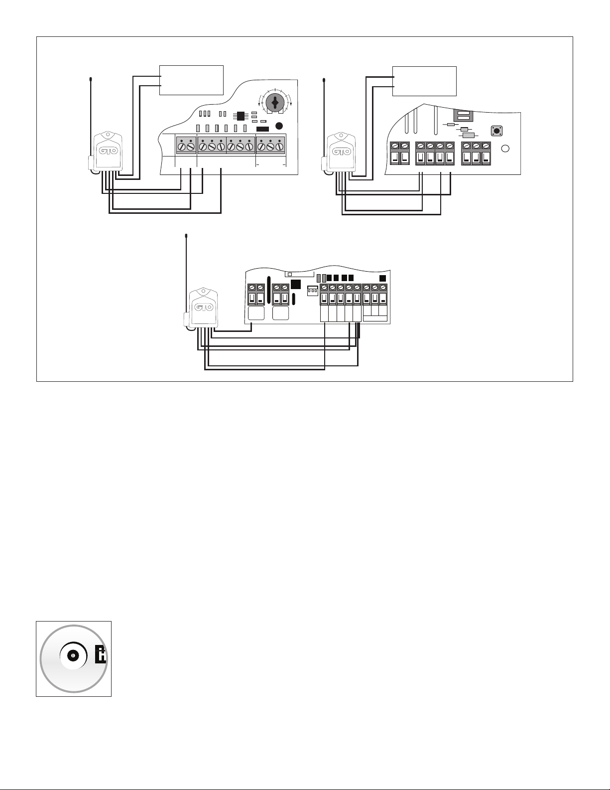
Learning an FM130 to an MM371, MM372, MM571 or MM572 Automatic Gate Opener.
1. With the power on for your control box, press and
hold the gate opener's middle, orange S3 button
( ) located on the control board until you hear
a beep, then release it
2. Take a battery out of the green FM130 transmitter
and put it back in. The control board should
beep.
3. Test the FM130 by closing the gate and removing
and replacing a battery in the green FM130
transmitter.
4. Proceed to "Test the System".
NOTE: If you hear three short beeps in succession, the
programming mode has timed out and you will need to
redo Steps 1-3.
To forget the FM130, simply follow steps 1 and 2 above
then test the keypad to verify that it no longer activates
the AGO.
Learning an FM130 to an MM271 or MM272 Automatic Gate Opener
1. Use the On/Off switch on the control box to power the system down.
2. Take the battery out of the green FM130 transmitter and put it back in.
3. While the red light is blinking on the FM130 transmitter, power the system on with the On/Off switch on the
control box
4. After the startup beep, there will be a long silence for about 10 seconds, followed by a continuous beep sound.
5. Test the FM130 by closing the gate and removing and replacing a battery in the green FM130 transmitter.
6. Proceed to “Test the System”
To forget the FM130, simply follow steps 1-5 above then test the sensor to verify that it no longer activates the AGO.
NOTE for MM271: The gate must be in the closed position with the arm extended to delete the FM130. The gate can be
in any position to learn it.
IF THE PROCESS FAILS ON THE MM271 OR MM272: You must use a dip-switch type transmitter (FM134, FM135,
MM3BT, RB741, or RB742) to program the FM130. Simply match the dip-switch patterns between the transmitter and
FM130 then learn the transmitter to the system.
Contact Tech Support for a complimentary dip-switch type transmitter to program the FM130 if you do not have one.
S4
S3
S2
LED1
LED2
LED3