Mighty Mule MMB200 User manual

Mighty Mule®
Battery Enclosure Kit
MMB200
Installation Instructions


3
TABLE OF CONTENTS
Enclosure Kit Installation Options............................................4
Package Contents........................................................5
Tools Required ..........................................................6
Mount the Battery Enclosure Kit.............................................7
MM271 Installation Preparation .............................................8
MM271 BATTERY INSTALLATION .....................................................10
MM272 Installation Preparation .............................................13
MM272 BATTERY INSTALLATION .....................................................13
Final MM271 Battery Enclosure Kit Setup .....................................16
MM271 Control Box – Battery Enclosure Kit Connection....................................16
Final MM272 Battery Enclosure Kit Setup .....................................16
MM272 Control Box – Battery Enclosure Kit connection....................................16
MM371W, MM372W, TS571W Battery Enclosure Kit Setup ........................17
Control Box – Battery Enclosure Kit Connection ..........................................17

4
ENCLOSURE KIT INSTALLATION OPTIONS
There are two available choices for Battery Enclosure Kit installations.
For MM271 and MM272 installations, the Battery Enclosure Kit will need to be installed separately from the Control Box (see
Figure 1). This method is NOT required for MM371W, MM372W and TS571W installations, but it may be used.
Separate Battery Enclosure Kit (required for MM271 and MM272)
Battery Enclosure Kit Combined with Control Box (available for MM371W, MM372W and TS571W)
This option allows MM371W, MM372W and TS571W owners to mount the Battery Enclosure Kit behind the Control Box and
cover.
See Mount the Battery Enclosure Kit on page 7.
Battery Box
Control Box
Figure 1
1. Once the Battery Enclosure Kit is mounted, the Control Box will mount onto the Battery Enclosure Kit.
2. The Control Box Cover is then attached to the to the Control Box. The provided Battery Enclosure Kit Cover may be
discarded.

5
PACKAGE CONTENTS
(1) Battery Enclosure Kit and Cover
(4) Battery Enclosure Kit Cover Screws
(4) Mounting Screws
(1) 12V 7 Ah Battery
(FM150 or RB500)
NOTE: An additional FM150 or RB500 is
recommended for solar installations (purchased
separately).
(1) Strain Relief Fitting
(2) IDC Self Stripping Connectors
NOTE: ONLY the use of the supplied IDC
Connector will not void your Mighty Mule
product warranty.
(1) Battery Harness A
(1) Battery Harness B
To Battery Harness B
To Control
Board
To Battery To Battery
To Battery
Harness A
Black –
Red +
Black –
Black –
Red +
Red +

6
TOOLS REQUIRED
Phillips Head Screwdriver
Wire Stripper (for use in cutting wires) or Wire
Cutters
(Optional) Pliers
(May be used to press and secure the IDC Self
Stripping Connectors.)
Drill with 1/2” and 7/32” Drill Bits

7
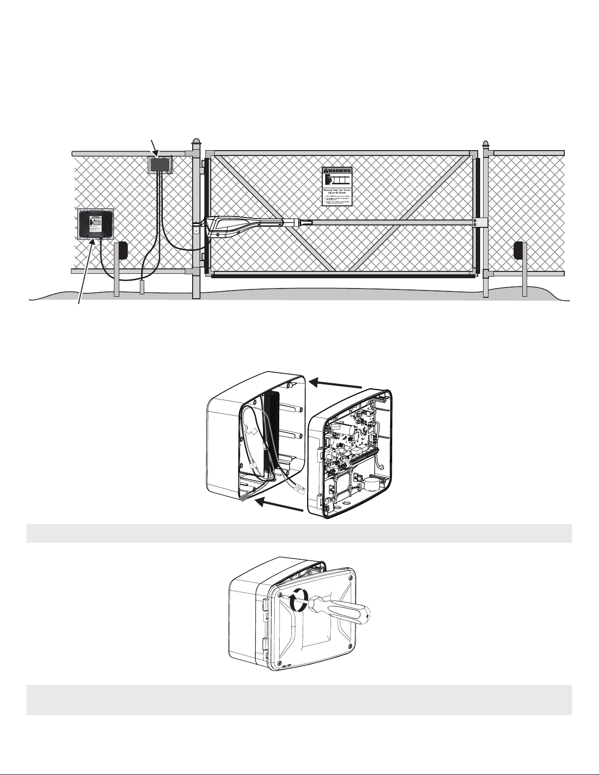
MOUNT THE BATTERY ENCLOSURE KIT
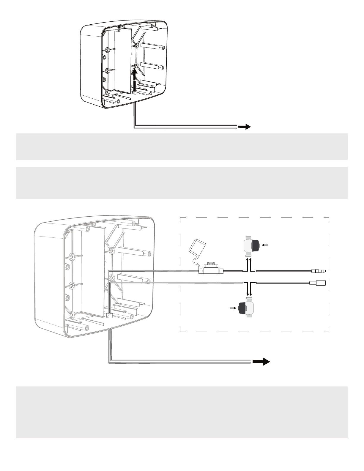
1. Insert the Strain Relief tting into the access
hole on the bottom of the Battery Enclosure
Kit, then snap it into place.
2. Identify a suitable mounting location for the
Battery Box, within 6’ of the control box.
NOTE: For MM371W, MM372W and TS571W
systems, the Battery Box may be placed where
the Control Box is currently located. The Control
Box will be attached to the Battery Box at the
end of the process.
NOTE: If the mounting surface is not wood (such
as a metal post), you must use a wood panel
between the box and the metal post which
requires additional hardware (not supplied).
3. Once you’ve identied a suitable mounting
location, mount the Battery Enclosure Kit
using the provided mounting screws.
NOTE: Orient the Battery Enclosure Kit with the
arrow on the inside of the box pointed up.
OR

8
MM271 INSTALLATION PREPARATION
In order to install the Battery Kit to your existing MM271 gate arm system, the wiring harness currently connected to the
MM271 Control Box will need to be modied using a section of a newly provided wiring harness. NOTE: DO NOT attempt to
disconnect the wiring harness from the MM271 Control Box.
Red +
Black –
Red+
Black–
Cut and Discard
1. Cut the section of the provided Battery Harness A.
POWER
OFF
AUTO CLOSE
TIME
MIN MAX
STALL
FORCE
ON OFF
SG1
ED1
K1
06
AVR-ISP
D1
C2
C7
C15
LED3
D15
R20
IC4
D16
D13
D14
K2
BATT- BATT+
STATUS
EDGE
COM
LOCK+
LOCK -
M_BLK
M_RED
VAR2
GRN
VAR3
VAR3
VAR1
VAR4
VAR5
PF1
VAR6
WHT
CYCLE
EXIT
SAFETY
COM
CHGR
CHGR
Red+
Black–
Currently Connected to
MM271 Control Box
Cut and Discard
2. POWER OFF THE MM271 CONTROL BOX.
3. Cut the indicated section from the existing wiring harness currently connected to the MM271 Control Box.
NOTE: DO NOT attempt to disconnect the existing MM271 wiring harness from the Control Box.
Battery Harness A
Existing Battery Harness

9
NOTE: DO NOT PERFORM THIS STEP BEFORE FOLLOWING STEP 3!
The IDC Self Stripping Connectors will not t through the Strain Relief Fitting and must be connected after the existing
battery harness has been fed through.
Connected to
MM271 Control Box
Press black cap
down to secure
Press black cap
down to secure
5. Splice the two harness sections together using the two provided IDC Self Stripping Connectors, ensuring that the new
harness will rest within the Battery Enclosure Kit.
Insert alike wires (Black-to-Black and Red-to-Red) into one connector, then use press rmly with your thumb (or use
pliers) to press down on the black cap to snap and secure the connection.
NOTE: Once an IDC Self Stripping Connector is snapped and secured, it cannot be removed without damage.
INSIDE BATTERY BOX
Connected to
MM271 Control Box
Splice Wires of Existing
Battery Harness
4. Feed the spliced end of Battery Harness A (connected to the MM271 Control Box) through the Strain Relief tting from
underneath the Battery Enclosure Kit. The wiring harness will then need to be constructed and sealed inside the Battery
Enclosure Kit.

10
MM271 BATTERY INSTALLATION
This section covers battery installation for the MM271. However, this set of instructions for a separate Control Box installation
can also be used for MM371W, MM372W and TS571W installations. See MM371W, MM372W, TS571W Battery Enclosure Kit
Setup, page 17, for instructions on the preferred method for MM371W, MM372W and TS571W installations.
To complete construction of the required harness, connect Battery Harness A to Battery Harness B (refer to the diagrams on
this page).
NOTE: Either end of the newly constructed Battery Harness may be connected to the rst battery. The opposite battery
connection is available for a second battery.
Battery Harness A
Battery Harness B
Red +
Black –
Black –
Red +
Black –
Black –
Red +
Red + Red +
Black –
Connect to
Control Box
Connect to
Battery 1
Connect to
Battery 2

11
1. Connect the battery harness
to the battery as shown - red
to positive, black to negative
terminals.
2. Place the rst installed battery
into the right side of the Battery
Enclosure Kit with the terminals
facing to the right and towards
the top of the Battery Enclosure
Kit.
Connects to
Control Box
OPTIONAL SECOND BATTERY
• If you’ll be installing a second
battery, connect the second set
of harness connectors to the
battery.
• Insert the battery into the left side
of the Battery Enclosure Kit with
the terminals facing outward.
NOTE: If no second battery is to be
installed, leave the second battery set
of connectors not connected.

12
3. With the battery(s) in place and
connected to the wiring harness,
use the four provided screws to
secure the Battery Enclosure Kit
cover.

13
Connect to
Control Box
Connect to
Battery Harness B
Red+
Red+
Red+
Black–
Black–Black–
Feed the Control Box end of Battery Harness A through the Strain Relief tting as displayed above.
MM272 INSTALLATION PREPARATION
MM272 BATTERY INSTALLATION
This section covers battery installation for the MM272. However, this set of instructions for a separate Control Box installation
can also be used for MM371W, MM372W and TS571W installations. See MM371W, MM372W, TS571W Battery Enclosure Kit
Setup, page 17, for instructions on the preferred method for MM371W, MM372W and TS571W installations.
To complete construction of the required harness, connect Battery Harness A to Battery Harness B (refer to the diagrams on
this page).
NOTE: Either end of the newly constructed Battery Harness may be connected to the rst battery. The opposite battery
connection is available for a second battery.
Battery Harness A
Battery Harness B
Red +
Black –
Black –
Red +
Black –
Black –
Red +
Red + Red +
Black –
Connect to
Control Box
Connect to
Battery 1
Connect to
Battery 2

14
1. Connect the battery harness
to the battery as shown: red
to positive, black to negative
terminals.
2. Place the rst installed battery
into the right side of the Battery
Enclosure Kit with the terminals
facing to the right and towards
the top of the Battery Enclosure
Kit.
Connects to
Control Box
OPTIONAL SECOND BATTERY
• If you’ll be installing a second
battery, connect the second set
of harness connectors to the
battery.
• Insert the battery into the left side
of the Battery Enclosure Kit with
the terminals facing outward.
NOTE: If no second battery is to be
installed, leave the second battery set
of connectors not connected.

15
3. With the battery(s) in place and
connected to the wiring harness,
use the four provided screws to
secure the Battery Enclosure Kit
cover.

16
POWER
OFF 120
AUTO CLOSE
TIME
MIN MAX
STALL
FORCE
ON OFF
SG1
ED1
K1
06
AVR-ISP
D1
C2
C7
C15
LED3
D15
R20
IC4
D16
D13
D14
K2
BATT- BATT+
STATUS
ANT SHLD
S9.8874
EDGE
COM
LOCK+
LOCK -
M_BLK
M_RED
VAR2
GRN
VAR3
VAR3
VAR1
VAR4
VAR5
PF1
VAR6
WHT
CYCLE
EXIT
SAFETY
COM
CHGR
CHGR
FINAL MM271 BATTERY ENCLOSURE KIT SETUP
MM271 Control Box – Battery Enclosure Kit Connection
VAR5
VAR6
K1
PF1
K2
BATT +
BATT –
K3
K4
VAR4
VAR3
VAR2
VAR1
MIN MAX OFF
≤JP1
REMOVE JUMPER FOR
PUSH TO OPEN OPTION
120
SEC.
R4722
STALL FORCE
OPEN < JOG > CLOSE
PWR. SET
LIMIT
1st OPR.
2nd OPR.
STATUS
AUTO CLOSE
SFTY.
EXIT
CYCLE
EDGE
SENSOR
COMMON
LOCK+
LOCK–
WHT
GRN
RED
BLK
WHT
GRN
SECOND OPR.FIRST OPR.
RED
BLK
CHARGE
ON OFF
OR
SOLA
FINAL MM272 BATTERY ENCLOSURE KIT SETUP
MM272 Control Box – Battery Enclosure Kit connection

17
GRN
WHT
BAT+
AUTO
CLOSE
RESET
PULL
STAGGER
WARNING
BAT–
GRN
WHT
RED
BLK
RED
BLK
COM
COM
CYCL
SAFE
EXIT
SHDW
AUX
V+
AUX
V-
LOCK
V+
LOCK
V-
CLOSE
EDGE
OPEN
EDGE
PRIMARY
SECONDARY
LOCK AUX
SW1
SW2
PUSH
12345
+
TERM6
+–
Battery Power Access
Control Box
1. In order to install the Battery Kit, you’ll need to provide wiring access from the Control Box to the Battery Enclosure Kit.
With a drill and 1/2” drill bit, drill out the plug designated for Battery Power Access.
DANGER/POISON
2. Connect the battery harness to the battery as shown: red to positive, black to negative terminals.
3. Place the battery into the right side of the Battery Enclosure Kit with the terminals facing to the right and towards the
top of the Battery Enclosure Kit.
MM371W, MM372W, TS571W BATTERY ENCLOSURE KIT SETUP
Control Box – Battery Enclosure Kit Connection

18
OPTIONAL SECOND BATTERY (Recommended for Solar installations)
• If you’ll be installing a second battery, connect the second set of harness connectors to the battery.
• Insert the battery into the left side of the Battery Enclosure Kit with the terminals facing outward.
NOTE: If no second battery is to be installed, leave the second battery set of connectors not connected.
Drill Hole
Location
4. With the 1/2” hole drilled, feed the Battery Harness connectors from the Battery Enclosure Kit through the Control Box’s
newly drilled access hole.
5. Use a 7/32” drill bit to drill out the holes required to secure the Control Box to the Battery Enclosure Kit. Use #10-14 x
3/4” Screws to attach the Control Panel to the Battery Enclosure Kit.
NOTE: Control Box mounting screws are not included with MM371W and MM372W.

19
GRN
WHT
BAT+
AUTO
CLOSE
RESET
PULL
STAGGER
WARNING
BAT–
GRN
WHT
RED
BLK
RED
BLK
COM
COM
CYCL
SAFE
EXIT
SHDW
AUX
V+
AUX
V-
LOCK
V+
LOCK
V-
CLOSE
EDGE
OPEN
EDGE
PRIMARY
SECONDARY
LOCK AUX
SW1
SW2
PUSH
12345
+
TERM6
GRN
WHT
BAT+
BAT–
RED
BLK
SECONDARY
SW1
SW2
TERM6
BLACK– RED+
+
+
–
–
BLACK– RED+
6. Connect the harness (Red+ to Red+) and (Black– to Black–).
7. Align the hinges of the Control Box cover, then close the cover.
NOTE: For MM371W, MM372W and TS571W, the Control Box and Cover can be attached to the Battery Enclosure Kit. In this
situation, the provided Battery Enclosure Kit Cover may be discarded.
8. Secure the cover with the four provided screws.
If desired, the battery enclosure can also be installed separately from the control box. To do so, simply follow steps outlined
for the MM272.

©2022 Nortek Security & Control LLC. Mighty Mule is a registered trademark of Nortek Security & Control LLC. All rights reserved.
Mighty Mule Sales: 800-543-4283 |Mighty Mule Technical Service 800-543-1236
For more information on Mighty Mule’s full line of Automatic Gate Operators, Gate Openers and Access Controls visit
www.mightymule.com
10031652 Rev-B
This manual suits for next models
5
Table of contents
Popular Camera Accessories manuals by other brands

Hanna Instruments
Hanna Instruments HI 740031 instruction manual

Westcott
Westcott 1040 Setup instructions

Really Right Stuff
Really Right Stuff WPF-QR2 installation instructions

Channel Vision
Channel Vision PRO 6210 instructions

BorMann
BorMann PRO BBP2002 quick start guide

Insignia
Insignia NS-DGPCS10-C Quick setup guide