Mighty Seven DG-585 User manual

1
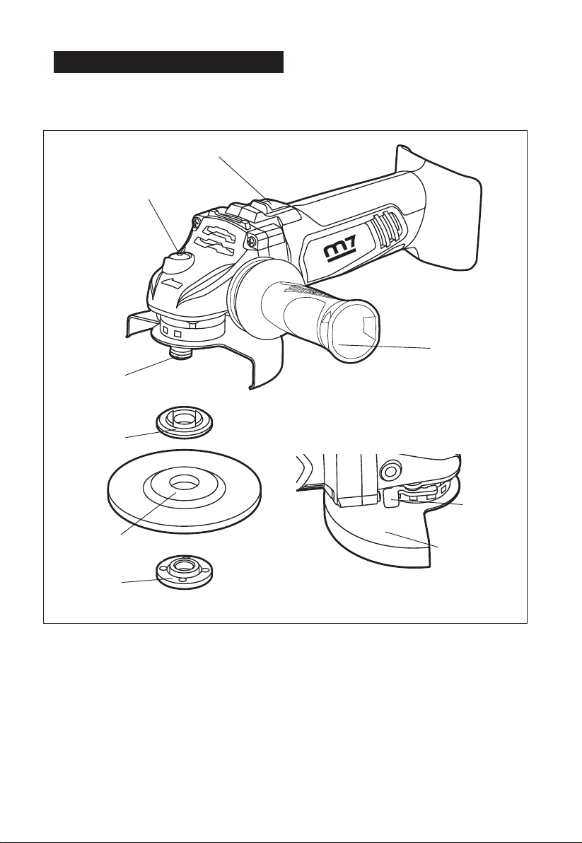
DESCRIPTION OF THE TOOL
OPERATING CONTROL
Switch button
Spindle-lock button
Grinding wheel
Spindle
Side handle
Guard-
adjusting
lever
Wheel guard
Inner flange
Outer flange
1

2
Rated speed 8000 RPM
Wheel diameter 5" (125 mm)
Arbor size M14*2
Tool weight (without battery) 3.2 lbs.(1.46kg)
SPECIFICATIONS
2
3
3
GENERAL SAFETY RULES
WARNING: Read all instructions. Failure to
follow all instructions listed below may result in
SAVE THESE INSTRUCTIONS
The term “power tool” in all of the warnings listed
below refers to your main operated (corded)
power tool or battery operated (cordless) power
tool.
1. WORK AREA SAFETY
1) Keep your work area clean and well lit.
Cluttered or dark areas invite accidents
2) Do not operate power tools in explosive
environments, such as in the presence of
create sparks, which may ignite the dust or
fumes.
3) Keep children and bystanders away while
operating a power tool. Distractions may cause
you to lose control.
2. ELECTRICAL SAFETY
1) Avoid body contact with grounded surfaces,
such as pipes, radiators, ranges, and
refrigerators. There is an increased risk of
electric shock if your body is grounded.
2) Power tool plugs must match the outlet. Never
modify the plug in any way. Do not use any
adapter plugs with grounded power tools.
reduce the risk of electric shock.
3) Do not expose power tools to rain or wet
conditions. Water entering a power tool will
increase the risk of electric shock.
4) Do not abuse the cord. Never use the cord for
carrying, pulling, or unplugging the power tool.
Keep the cord away from heat, oil, sharp edge,
or moving parts. Damaged or entangled cords
increase the risk of electric shock.
5) When operating a power tool outdoors, use an
extension cord suitable for outdoor use. Use of
a cord suitable for outdoor use reduces the risk
of electric shock.
6) If operating a power tool in a damp location
is unavoidable, use a residual current device
(RCD) protected supply. Use of an RCD
reduces the risk of electric shock.
Use the battery only with the charger listed:
BATTERY PACK CHARGER
DB1840 or DB-1850
3.PERSONAL SAFETY
1) Stay alert, watch what you are doing and use
common sense when operating a power tool.
Do not use a power tool while tired or under
A moment of inattention while operating power
tools may result in serious personal injury.
2) Use safety equipment. Always wear eye
protection. Safety equipment, such as dust
mask, non-skid safety shoes, hard hat, and
hearing protection, when used for appropriate
conditions, will reduce personal injuries.
3) Avoid accidental starting. Make sure that the
switch is in the “OFF” position before plugging
the tool into an electrical outlet. Carrying
plugging in power tools that have the power
switch “ON” invites accidents.
4) Remove any adjusting key or wrench before
turning the power tool on. A wrench or key left
attached to a rotating part of the power tool
may result in personal injury.
5) Do not overreach. Keep proper footing and
balance at all times. This enables better
control of the power tool in unexpected
situations.
6) Dress properly. Do not wear loose clothing or
jewelry. Keep your hair, clothing, and gloves
away from moving parts. Loose clothes,
jewelry, or long hair can be caught in moving
parts.
7) If devices are provided for the connection of
dust extraction and collection facilities, make
sure that these are connected and properly
used. Use of these devices can reduce dust-
related hazards.
8) Use clamps or another practical way to
support and secure the workpiece to a stable
platform. Holding the work by hand or against
your body leaves it unstable and may lead to
loss of control.
9) Do not use on a ladder or unstable support.
Stable footing on a solid surface enables
better control of the power tool in unexpected
situations.
DC-18
3

4
4
10)Keep handles dry, clean, and free from oil and
grease. Slippery hands cannot safely control
the power tool.
11)Always wear safety glasses with side shields.
Everyday glasses may have impact-resistant
lenses, but they are NOT safety glasses.
Following this rule will reduce the risk of eye
12)Protect your lungs. Wear a face or dust mask
if the operation is dusty. Following this rule will
13)Protect your hearing. Wear hearing protection
during extended periods of operation.
Following this rule will reduce the risk of
4.POWER TOOL USE AND CARE
1) Do not force the power tool. Use the correct
power tool for your application. The correct
safely at the rate for which it was designated.
2) Do not use the power tool if the switch does not
turn it ON and OFF. Any power tool that cannot
be controlled with the switch is dangerous and
must be repaired.
3) Disconnect the plug from the power source
and/or the battery pack from the power tool
accessories, or storing power tools. Such
preventive safety measures reduce the risk of
starting the power tool accidentally.
4) Store idle power tools out of the reach of
children and do not allow persons unfamiliar
with the power tool or these instructions
to operate the power tool. Power tools are
dangerous in the hands of untrained users.
5) Maintain power tools. Check for misalignment
or binding of moving parts, breakage of parts
and any other condition that may affect the
power tool’s operation. If damaged, have
the power tool repaired before use. Many
accidents are caused by poorly maintained
power tools.
6) Keep cutting tools sharp and clean. Properly
maintained cutting tools with sharp cutting
edges are less likely to bind and are easier to
control.
7) Use the power tool, accessories, blades, etc.
in accordance with these instructions and in
the manner intended for the particular type of
power tool, taking into account the working
conditions and the work to be performed. Use
of the power tool for operations different from
those intended could result in a hazardous
situation.
8) Hold power tools by the insulated gripping
surfaces when performing any operation in
which the cutting tool may contact hidden
wiring or its own cord. Contact with a “live”
wire will also make exposed metal parts of the
tool “live” and can shock the operator.
9) Know your power tool. Read the product
manual carefully. Learn the applications and
hazards related to this tool. Following this rule
10)Save these instructions. Refer to them
frequently and use them to instruct others
who may use this tool. If you lend this tool
to someone else, also lend them these
instructions.
5.BATTERY TOOL USE AND CARE
1) Make sure that the switch is in the OFF
position before inserting the battery pack.
Inserting the battery pack into power tools that
have the switch ON invites accidents.
2)
manufacturer. A charger that is suitable for one
when used with another battery pack.
3)
designated battery packs. Use of any other
4) When the battery pack is not in use, keep it
clips, coins, keys, nails screws, or other small
one terminal to another. Shorting the battery
5) Under abusive conditions, liquid may be
liquid contacts eyes, additionally seek medical
cause irritation or burns.
6) Battery tools do not have to be plugged into
in operating condition. Be aware of possible
hazards when not using your battery tool or
4

5
when changing accessories. Following this rule will
7) Do not place battery tools or their batteries
8) Do not crush, drop or damage the battery
pack. Do not use a battery pack or charger that
has been dropped or received a sharp blow.
Properly dispose of a dropped or damaged
battery immediately.
9)
Properly dispose of a dropped or damaged
battery immediately.
10)Batteries vent hydrogen gas and can explode
in the presence of a source of ignition, such
as a pilot light. To reduce the risk of serious
exploded battery can propel debris and
chemicals. If exposed to such debris or
area with water.
11)Do not charge a battery tool in a damp or wet
location. Following this rule will reduce the risk
of electric shock.
12)Under extreme usage or temperature
conditions, battery leakage may occur.
13)
If liquid contacts eyes, seek medical help.
irritation or burns.
14)If liquid comes in contact with your skin,
wash immediately with soap and water, then
15)If liquid from the battery gets in your eyes,
minutes, and then seek immediate medical
attention. Following this rule will reduce the
6.SERVICE
1)
repair person.
2) When servicing a power tool, use only identical
replacement parts.
3) Follow instructions in the Maintenance section of
this manual. Use of unauthorized parts or failure
to follow Maintenance instructions may create a
ADDITIONAL SAFETY
INSTRUCTIONS FOR GRINDING
OPERATIONS
1. Use only wheel types that are
recommended for your power tool and the
wheel. Wheels for which the power tool was
not designed cannot be adequately guarded
and are unsafe.
2. The grinding surface of centre depressed
wheels must be mounted below the plane
of the guard lip. An improperly mounted
wheel that projects through the plane of the
guard lip cannot be adequately protected.
3. The guard must be securely attached
to the power tool and positioned for
maximum safety, so the least amount of
wheel is exposed towards the operator.
The guard helps to protect the operator
from broken wheel fragments, accidental
contact with wheel and sparks that could
ignite clothing.
4. Wheels must be used only for
recommended applications. For example:
do not grind with the side of cut-off wheel.
Abrasive cut-off wheels are intended for
peripheral grinding, side forces applied to
these wheels may cause them to shatter.
that are of the correct size and shape
for your selected wheel. Proper wheel
the possibility of wheel breakage. Flanges
for cut-off wheels may be different from
grinding wheel flanges.
6. Do not use worn down wheels from larger
power tools. A wheel intended for a larger
power tool is not suitable for the higher speed
of a smaller tool and may burst. SP
5

6
SAFETY RULES FOR CHARGER
1) Before using battery charger, read all
instructions and cautionary markings in this
manual and on the battery charger, the battery
and the product using the battery to prevent
damage.
CAUTION: To reduce the risk of electric
shock or damage to the charger and battery,
charge only those lithium-ion rechargeable
charger’s label. Other types of batteries may
2) Do not use the charger outdoors or expose it
to wet or damp conditions. Water entering the
charger will increase the risk of electric shock.
3) Use of an attachment not recommended or
sold by the battery-charger manufacturer may
persons.
4) Do not abuse the cord or charger. Never use
the cord to carry the charger. Do not pull the
charger cord to disconnect the plug from
receptacle. Damage to the cord or charger
could occur and create an electric shock
hazard. Replace damaged cords immediately.
5) Make sure that the cord is located so that it
will not be stepped on, tripped over, come in
contact with sharp edges or moving parts,
This will reduce the risk of accidental falls,
the cord, which could then result in electric
shock.
6) Keep cord and charger from heat to prevent
damage to housing or internal parts.
7) Do not allow gasoline, oils, petroleum-based
products, etc. to come in contact with plastic
parts. These materials contain chemicals that
can damage, weaken, or destroy plastic.
8) An extension cord should not be used unless
absolutely necessary. Use of an improper
and electric shock. If an extension cord must
be used, make sure that:
The pins on plug of extension cord are the
same number, size and shape as those of the
plug on charger.
The cord is properly wired and in good electrical
condition
The size is large enough for AC ampere rating
The Cord Length (Feet) 25’ 50’ 100’
Cord Size (AWG) 16 16 16
NOTE: AWG = American Wire Gauge
9) Do not operate the charger with a damaged
cord or plug, which could cause shorting and
electric shock. If damaged, have the charger
repaired or replaced by an authorized service
technician at Service Center.
10)Do not operate the charger if it has received
a sharp blow, been dropped, or has
otherwise been damaged in any way. Take
it to an authorized service technician at
Service Center for an electrical check to
determine if the charger is in good working
order.
11)Do not disassemble the charger. Take it to
an authorized service technician at a
Service Center when service or repair is
required. Incorrect reassembly may result in
12)Unplug the charger from the electrical outlet
before attempting any maintenance or
cleaning to reduce the risk of electric shock.
13)Disconnect charger from the power supply
when not in use. This will reduce the risk of
electric shock or damage to the charger if
metal items should fall into the opening. It
will also help prevent damage to the charger
during a power surge.
14)Risk of electric shock. Do not touch the
uninsulated portion of output connector or
uninsulated battery terminal.
15)Save these instructions. Refer to them
frequently and use them to instruct others
who may use this tool. If you lend this tool to
someone else, also lend these instructions
to them to prevent misuse of the product and
possible injury.
6
7
7
WARNING: Some dust created by power Cutting
contains chemicals known to cause cancer,
birth defects or other reproductive harm. Some
examples of these chemicals are:
lead from lead-based paints
Arsenics and chromium from chemically
reacted lumber.
Your risk from these exposures varies, depending
on how often you do this type of work. To reduce
your exposure to these chemicals: work in a well
ventilated area, and work with approved safety
equipment.
ACCESSORIES
Angle Grinder 1
Charger 1
Battery pack 2
Be sure to check the accessories as it is subject
to change by areas and models.
OPERATION
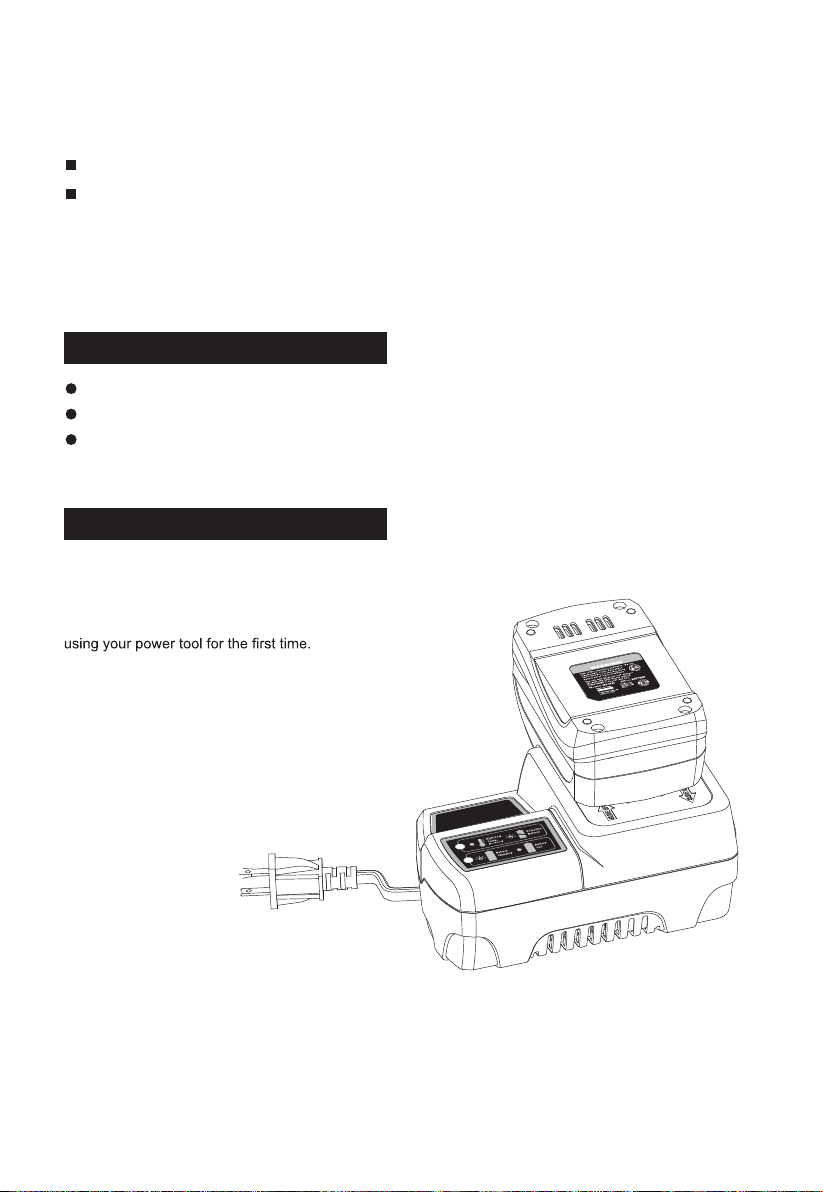
1.BATTERY CHARGING
The battery is supplied partially charged. To
ensure full capacity of the battery, completely
charge the battery in the battery charger before
A fully discharged battery pack will charge
in 50 minutes for DB1840 in a surrounding
temperature between 32° F (0° C) and 104° F
(40° C).
1. Charge the Lithium-Ion battery pack with the
correct charger.
2. Connect the charger to a power supply.
3. Align the raised ribs of the battery pack with
the slot in the charger.
4. Slide the battery pack onto the charger .
5. The charger will communicate with the
battery pack to evaluate the condition of the
battery pack.
6. The POWER BAR LED lights will cycle from
right to left during charging. This is part of the
normal charging operation.
7. After charging is complete, the green LED
on the charger will come on and the POWER
BAR LED lights will go displayed when the
POWER BAR button is pressed while the
battery pack is on the charger.
8. The battery pack will fully charge if left on the
charger, but it will not overcharge.
NOTE: For your convenience, the charger can
operate with most generators and inverters
rated at 300 watts or higher.
7

8
8
2. LED FUNCTIONS OF CHARGER
3. POWER BAR
This Lithium-Ion battery pack is equipped with a POWER BAR, which is used to display the battery
pack’s remaining run time. Press the POWER BAR button to display the LED lights. The LED lights
will stay lit for approximately 4 seconds.
NOTE: The POWER BAR can be used whether the battery is attached or removed from tool.
LED INDICATOR BATTERY PACK RED LED GREEN LED ACTION
HI/LO TEMP.
(SEE MANUAL) Hot/Cold battery On Off Charging will begin when
battery returns to 0oC-40oC
DEFECTIVE
BATTERY Defective Flashing Off Battery pack or Charger is
defective
BATTERY
CHARGING Charging Off Flashing Charging
BATTERY
FULL Fully charged Off On Charging is complete
Maintenance charging
4. LOW-BATTERY CAPACITY INDICATOR
If LED worklights on the POWER BAR begins
trigger switch on the angle grinder is
depressed, the battery pack’s power has run
out, and the battery pack should be recharged.
Unlike other battery pack types, Lithium-Ion
battery packs deliver fade-free power for their
entire run time. The tool will not experience a
slow, gradual loss of power as you work. To
signal that the battery pack is at the end of its
run time and needs to be charged, the power
to the tool will drop quickly. The POWER BAR
when the battery is completely discharged.
When this happens, remove the tool from the
workpiece, and charge the battery pack as
needed.
NOTE: The POWER BAR may also display four
temperature situation.
5. WHEN TO CHARGE THE
BATTERY PACK
The Lithium-Ion battery can be charged at any
time and will not develop a “memory” when
charged after only a partial discharge. It is not
necessary to run down the battery pack charge
before recharging. Remove the battery pack
from the tool when convenient for you and your
job.
Use the POWER BAR to determine when you
need to recharge the battery pack.
80-100% Charge
60-79% Charge
40-59% Charge
20-39% Charge
Under 20% Charge
Completely Discharged
High/low temperature
You can “top-off” your battery pack’s charge
before starting a big job or long period of use.
8
9
WARNING:
If any part is broken or
missing, DO NOT attempt to plug in the
power cord, attach the battery, or operate
the tool until the broken or missing part is
replaced. Failure to do so could result in
possible serious injury.
WARNING:
Do not attempt to mod -
ify this tool or create accessories not rec -
ommended for use with this tool. Any such
could result in a hazardous condition lead -
ing to possible serious injury.
WARNING:
Your tool should never
be connected to the power source when
you are assembling parts, making adjust -
ments, installing or removing application
tools, cleaning, or when it is not in use.
Disconnecting the tool will prevent acci -
dental starting, which could cause serious
personal injury.
CONTENTS
,hcnerw,eldnahedis,rednirgelgnasseldroC
5” grinding wheel and instruction
manual.
UNPACKING
1. Carefully remove the tool and any
accessories from the box. Make sure that all
items listed in the packing list are included.
2. Inspect the tool carefully to make sure
that no breakage or damage occurred
during shipping.
3. Do not discard the packing material
until you have carefully inspected and
satisfactorily operated the tool.
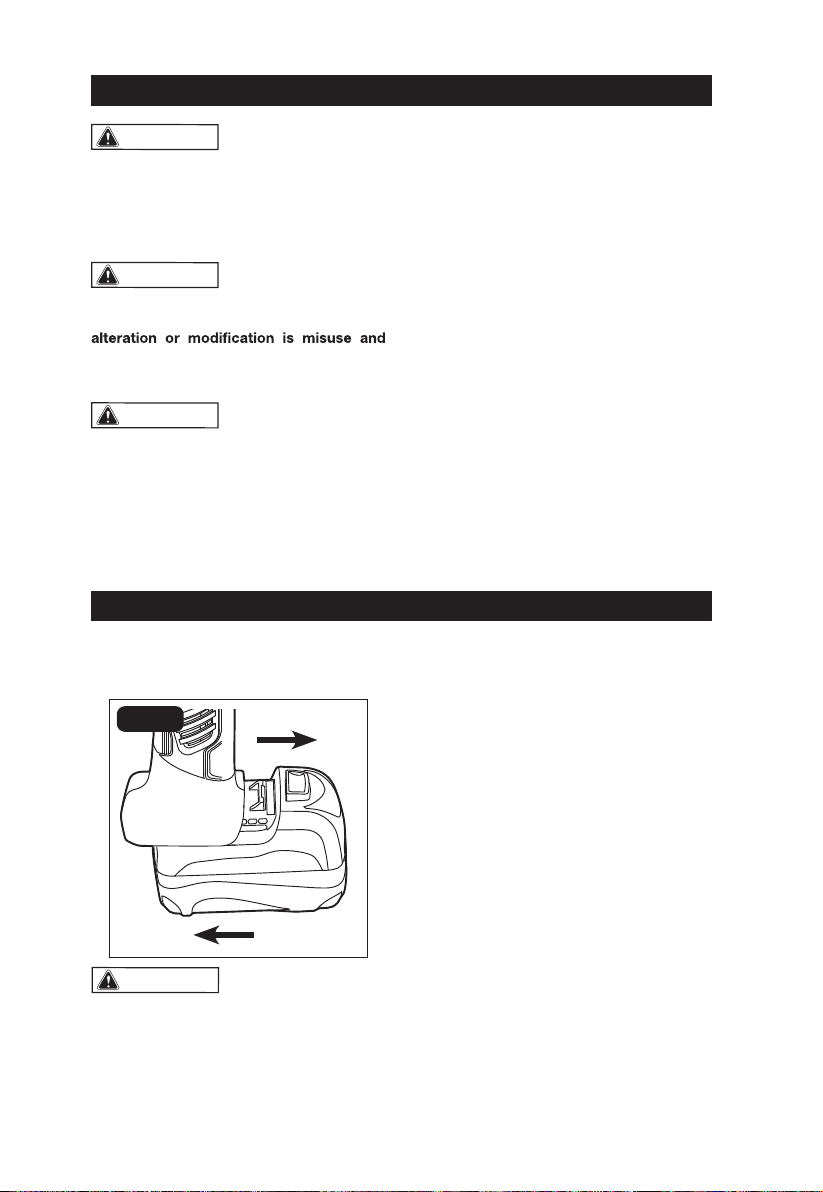
TO ATTACH THE
BATTERY PACK (FIG. 1)
FIG. 1
Attach
Detach
WARNING:
To avoid the possibility
of accidental starting, always take care not
to activate the trigger switch when you are
attaching the battery pack or performing other
adjustments to the tool.
1. Make sure that the angle grinder is
turned off.
2. Align the raised rib on the battery pack
with the grooves on the bottom of the tool,
and then attach the battery pack to the
angle grinder.
NOTICE: When attaching the battery pack
to the tool, make sure that the raised plat -
form on the pack aligns with the grooves
on the bottom of the tool and that the
latches snap properly into place. Improper
assembly of the battery pack can cause
damage to internal components.
TO DETACH BATTERY
PACK (FIG.1)
1. Make sure that the angle grinder is
turned off.
ASSEMBLY
OPERATION
9

10
2. Depress the battery-release button
located on the front of the battery pack to
release the battery pack.
3. Pull the battery pack forward to remove it
from the tool.
ON/OFF SWITCH (FIG. 2)
WARNING:
Firmly grasp the body of
the tool and the side handlebefore starting.
The tool is switched “ON” with the switch
button located at the top of the motor housing.
The switch can be locked in the “ON” position,
a convenience for long grinding operations.
The symbol “O” on the motor housing
indicates OFF; the symbol “l” indicates ON.
1. To turn the tool ON without locking it,
slide the switch button forward by applying
pressure only at the rear portion of the button.
2. To unlock the switch and turn the tool
OFF, press and release the rear portion of
the switch button; it will return to the OFF
position automatically.
FOR CONTINUOUS
OPERATION (FIG. 2)
1. Push the switch button forward to the ON
position and press the front of the button
down until the switch clicks into position.
2. To unlock the switch and turn the
tool OFF, press the rear of the button.
INSTALLING THE SIDE
HANDLE (FIG. 3)
The side handle is used to guide and
balance the tool and can be threaded into
the front housing on either side of the
tool, depending on personal preference
and comfort. Use the side handle for
safe control and ease of operation.
WARNING:
Failure to remove the
battery pack from the cordless angle grinder
when assembling parts, making adjust -
ments, or changing application tools could
result in accidental starting and cause seri -
ous injury.
1. Remove the battery pack from the
angle grinder.
2. The side handle may be installed on
the right side or the left side of the tool.
Thread the side handle into the desired
operating position.
3. Securely tighten the side handle by
turning it clockwise.
OPERATION
FIG. 2 Switch button
FIG. 3
10
11
ADJUST THE GUARD (FIG. 4)
WARNING:
Failure to remove the
battery pack from the cordless angle grinder
when assembling parts, making adjust -
ments, or changing application tools could
result in accidental starting and cause seri -
ous injury.
1. Remove the battery pack from the
angle grinder
2. Press the guard-adjusting lever, and hold
it to loosen the guard.
3. Rotate the guard to the desired position
and make sure that the lever lines up with
notches on the guard.
4. Release the guard-adjusting lever to lock the
guard; verify that the lever secures the guard.
WARNING:
ALWAYS use the guard
when grinding with a grinding wheel. It has
been designed for use only with the guard
attached. Attempting to use the grinder
with the guard removed will result in loose
particles being thrown against the opera -
tor and possibly serious personal injury.
WARNING:
Only use the guard with
grinding wheels. Make sure that the guard-
adjusting lever secures the guard before
operation. Keep the guard between you
and wheel. Do not direct the guard open -
ing towards your body.
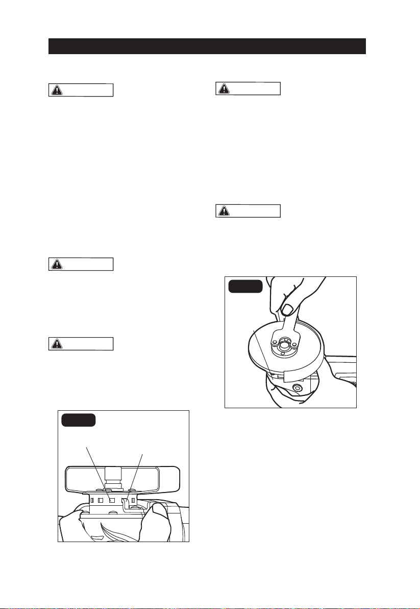
MOUNTINGTHE WHEEL (FIG. 5-6)
WARNING:
Only use grinding
wheels for which the maximum safe operat -
ing speed is rated at or above 11000 RPM.
Use only Type 27 wheels with the thickness
of 1/4” (6 mm), such as the one provided with
this product. Never attach a Type 1 straight
or cut-off wheel to this angle grinder. This
product is only designed for grinding. Use
for any other purpose is not recommended
and creates a hazard, which will result in se -
rious injury.
WARNING:
Failure to remove the
battery pack from the cordless angle
grinder when assembling parts, making
adjustments, or changing application tools
could result in accidental starting and
cause serious injury.
FIG. 5
Spindle-lock
button
1. Remove the battery pack from the
angle grinder.
2. Make sure that the guard is securely in
place. Depress and hold the spindle-lock
button. Loosen the outer flange with the
supplied wrench while holding the spindle-
lock button down (FIG. 5).
3. Place the inner flange on the spindle;
make sure that the flange is positioned so
that the shape of the opening in the flange
corresponds with the shape at the base of
the spindle.
OPERATION
FIG. 4
Guard-adjusting
lever
Notch on the
guard
11

12
4. Place the grinding wheel on the spindle.
Check the rated speed on the grinding
wheel. DO NOT use a wheel with a rated
speed lower than the speed shown on the
grinder nameplate.
5. Thread the outer flange on the spindle
with the flat side of the flange facing up,
making sure that the opening in the wheel is
positioned around the raised portion of the
outer flange (FIG. 6).
6. Press the spindle-lock button to prevent
movement of the spindle.
;desserpednottubkcol-eldnipsehtpeeK.7
ybegnalfretuodedaerhtehtnethgit
turning it clockwise with the wrench (FIG. 6).
WARNING:
Keep the guard between
you and the wheel. Do not direct the guard
opening toward your body.
FIG. 6
Outer flange
Inner
flange
Spindle
Grinding wheel
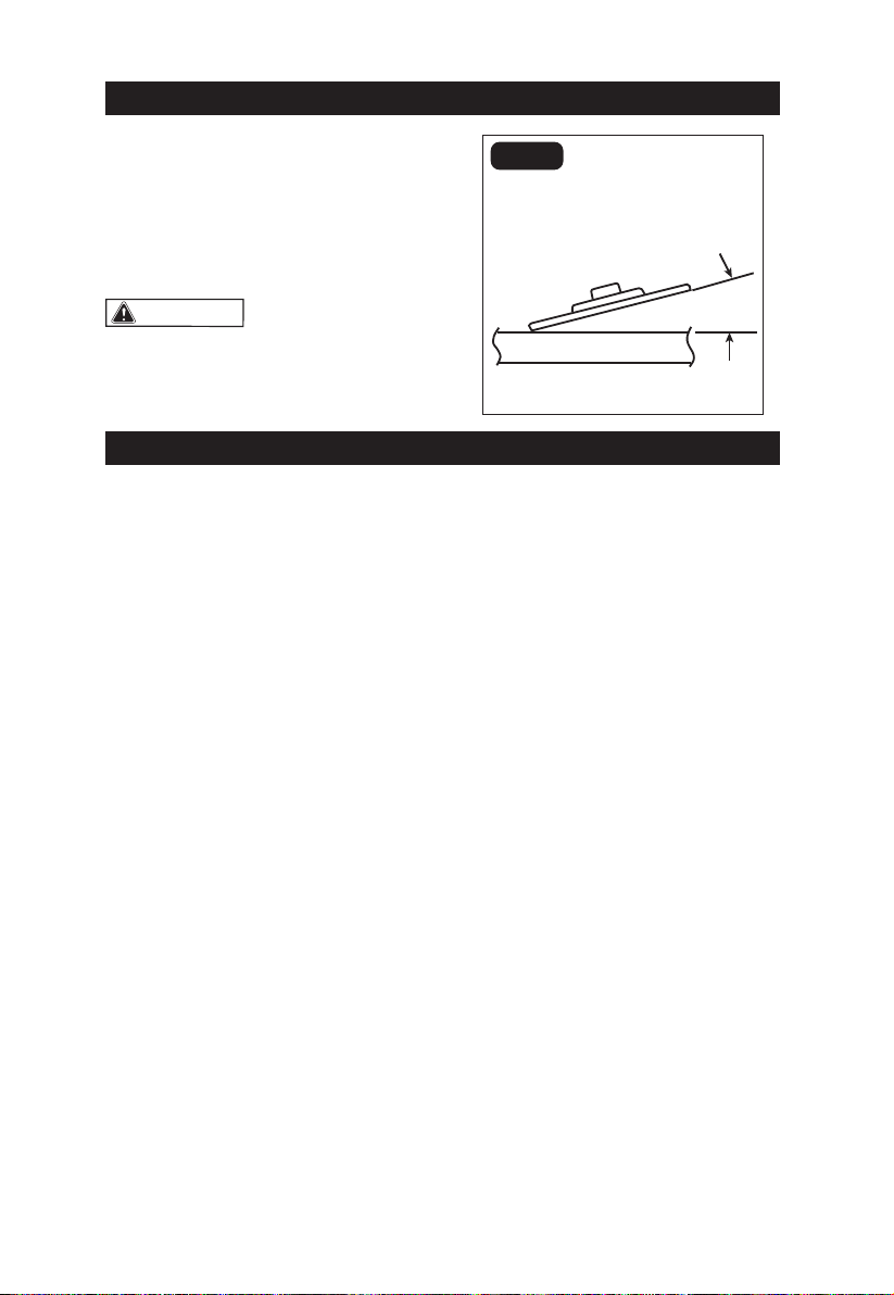
GRINDING OPERATION (FIG. 7)
WARNING:
Only use grinding wheels
for which the maximum safe operating speed
is rated at or above 11000RPM. Never use
damaged or imbalanced grinding wheels.
Do not exceed the recommended wheel
diameter. Grinding wheel type 27 is
recommended for use on this grinder.
WARNING:
Firmly grasp the body of
the tool and the side handle before starting.
1. If you have just installed an accessory or are
beginning a period of work, test it by letting
it spin for one minute before applying it to
the workpiece. Out-of-balance or damaged
accessories can mar workpiece, damage the
tool, and cause stress that may cause accessory
failure.
2. Use a clamp, vise or other practical means to
hold your work, freeing both bands to control
the tool.
3. Hold tool securely with both hands.
4. start the tool.
5. Allow accessory to come to full speed before
beginning work.
6. Control pressure to surface contact between
accessory and workpiece. Too much pressure
slows speed.
7. When finished, turn off the tool and make
sure it comes to a complete stop before laying
it down.
GRINDING TIPS
•Use a clamp, vise or other practical means
to hold your work, freeing both hands to
control your tool. Firmly grasp the body of tool
and the side handle before starting and while
the tool isin operation.
•Efficient grinding is achieved by controlling
the pressure and keeping the angle between
the wheel and the workpiece at 10° to 15°
(FIG. 7). If the angle is too shallow the tool is
difficult to control. If the angle is too steep,
the pressure is concentrated on a small area,
causing burning tothe work surface.
•Move the angle grinder back and forth with
moderate pressure to avoid discoloring the
workpiece, overheating the workpiece and
creating ridges.
• Never use a cut-off wheel to grind a
work piece.
•Always hold the tool properly so that sparks
and grinding dust fly away from the body.
• Start the tool before applying the
accessory to workpiece and let the tool come
to full speed before contacting the workpiece.
Lift the tool from the workpiece before turning
the tool OFF.
OPERATION
12
13
• When using a new grinding disc, do not
move the disc in a forward direction on the
workpiece. Doing so will cause the edge of the
disc to cut into the surface of the workpiece.
While grinding, the direction of movement
should be backward, toward the operator
(FIG 7).
WARNING:
Sparks are generated
when grinding metal. Take care that no
combustible material presented in the area of
flying sparks.
GENERAL MAINTENANCE
Using compressed air may be the most
effective cleaning method. Always wear
safety goggles when cleaning tools with
compressed air. Periodic maintenance
allows for long life and trouble-free operation.
A cleaning, lubrication and maintenance
schedule should be maintained.
1. Avoid dropping or otherwise causing impact
to the tool and keep it from oil and grease.
2. Inspect the screws periodically. If the
screws loosen, tighten them immediately, to
avoid serious accident.
3. Clean all parts of the tool; clean dust and
debris from vents. Keep the tool clean, dry
and free of oil or grease.
4. Avoid using solvents when cleaning
plastic parts. Most plastics are susceptible
to damage from various types of commercial
solvents and may be damaged by their use.
Use clean cloths and mild soap to remove
dirt, dust, etc.
LUBRICATION
All of the bearings in this product are
lubricated with a sufficient amount of
high grade lubricant for the life of the
unit under normal operating conditions.
Therefore, no further lubrication is required.
STORAGE AND HANDLING OF
GRINDING WHEELS
When not in use, grinding wheels should
be stored carefully in a rack or box to
protect them from chipping or breakage.
All grinding wheels must be handled
carefully to prevent dropping and bumping.
OPERATION
MAINTENANCE
10°~ 15°
FIG. 7
13

14
TROUBLESHOOTING
PROBLEM CAUSE OF THE PROBLEM SOLUTION
The motor stops
running Battery is empty Charge the battery pack
The angle grinder
does not work
The switch is in the “ON”
position when attaching the
battery pack
Turn off the angle grinder first and
re-start the tool
The tool is running
slowly Thegrinder wheel is worn outReplace the grinding wheel on the tool
TOOL MAINTENANCE
WARNING: Before any work on the
machine itself, remove the battery pack from
the angle grinder.
1. Inspect the screws periodically. If the
screw loosen, tighten them immediately, to
avoid serious accident.
2. Inspect tool cords periodically. If damaged,
have repaired at your nearest Authorized
Service Center.
3. Clean all parts of the tool; clean dust and
debris from vents. Keep the tool clean, dry
and free of oil or grease.
4. All service MUST only be performed by
Authorized Service Center. ALWAYS
use only accessories that are recommended
for this tool.
5. Avoid using solvents when cleaning plastic
parts. Most plastics are susceptible to damage
from various types of commercial solvents and
may be damaged by their use. Use clean cloths
and mild soap to remove dirt, dust, etc.
WARNING: Do not allow the water entering
the motor and the tool full immersed in the
ware, which will result in motor malfunction and
electric shock.
Store the batteries below 35 °C
Do not store batteries in high temperature or
high humidity environments.
It is recommended to store the batteries fully
charged.
ENVIRONMENT PROTECTION
1. Tool, accessories and packaging should be
sorted for environment-friendly recycling.
2. Power tools and accessories at the end of
their service life still contain large amounts of
valuable raw materials and plastics which can
likewise be fed back into a recycling process.
3. Some dust created by working contains
harmful chemicals must be collected by
special garbage re- cycle site.
SERVICE
1.
2. Warranty do not apply in case of normal wear,
overload or improper use of the tool.
In case of guarantee, repair or purchase of
replacement parts, always contact the qualified
service center.
And supplied with the efficient service card and
invoice.
14

15
Serial Number: Please refer to the tool
Cordless Angle Grinder with Battery Pack
Item No.: DG585 / DB1850 (Tool / Battery Pack)
18~20 Vd.c., 5.0 Ah, Li-ion Battery, 5” Angle Grinder
n0= 8000 rpm
of (MD) Machinery Directive 2006/42/EC, (LVD) Low Voltage Directive 2006/95/EC, (EMC)
Electromagnetic Compatibility Directive 2004/108/EC and Directive 2011/65/EU on ROSH and their
amendments and is manufactured and tested according to the following standards:
EN 60745-1, EN 60745-2-2, EN 55014-1, EN 61000-3-2, EN 61000-3-3, EN 55014-2, and EN 50581
Declared in: Taichung, Taiwan
Dated:2018/01/01
Jonney Chen
Declared by: QA Manager
Manufacturer:
Mighty Seven International Co., Ltd.
No. 70-25, Ching Quang Rd., Wujih Dist.,
Taichung City, 41466 Taiwan
http://www.mighty-seven.com
King Tony France
3 Rue des imprimeurs ZI République Nord 1.
86000 POITIERS FRANCE
TEL: (+33)5-49-30-30-90
E-MAIL: christian.aubineau@kingtony.eu
Signature
Original Language
ECDECLARATION OFCONFORMITY
30
Jay Lin
15

16
1/2" Dr. Cordless Impact Wrench
ltem No DG-585
K02
K01
K03
31
5" Cordless Angle Grinder
16

17
DG-585
NO. PART NO. DESCRIPTION Q'TY
1 DG-585P01 Wrench
2 DG-585P02 Outer Flange 1
3 DG-585P03 Inner Flange 1
4 DG-585T04 Tapping Screw ( 3PCS ) 1SET
5 DG-585P05 Plate 1
6 DG-585P06 Guard 1
7 DG-585T07 Screw With Washer ( 4PCS ) 1SET
8 DG-585P08 Output Shaft 1
9 DG-585P09 Plain Washer 1
10 DG-585P10 Slotted Shoulder Screw 1
11 DG-585P11 Lever 1
12 DG-585P12 Compression Spring 1
13 DG-585P13 Gear Case Cover 1
14 DG-585P14 Bevel Gear 1
15 DG-585P15 Oil Impreging Bearing 1
16 DG-585P16 Spindle Lock 1
17 DG-585P17 O Ring 1
18 DG-585T18 Tapping Screw ( 4PCS ) 1SET
19 DG-585P19 Pin Knob 1
20 DG-585T20 Spring 1SET
NO. PART NO. DESCRIPTION Q'TY
22 DG-585P22 Gear Case 1
23 DG-585P23 Bevel Pinion 1
24 DG-585P24 Ball Bearing 1
25 DG-585P25 Circlips For Shaft 1
26 DG-585P26 Rubber Ring 1
27 DG-585P27 Bearing Retainer 1
28 DG-585P28 Rotor 1
29 DG-585P29 Ball Bearing 1
30 DG-585P30 1
31 DG-585P31 Stator 1
32 DG-585P32 PCB Assembly 1
33 DG-585P33 Switch Button 1
34 DG-585P34 Left Housing 1
35 DG-585P35 Switch Actuator 1
36 DG-585P36 Spring 1
37 DG-585P37 Right Housing 1
38 DG-585T38 Tapping Screw ( 4PCS ) 1SET
K01 DG-585K01 Spindle ASSY ( 8~14 ) 1SET
K02 DG-585K02 Gear Case ASSY (15,16,17
,19,20 ) 1SET
K03 DG-585K03 "Rotor ASSY (23,24, 2 5
,27,28,29 ) 1SET
21 DG-585P21 Handle 1
32 17

18
18

1
DESCRIPTION DE L'OUTIL
COMMANDE DE FONCTIONNEMENT
Interrupteur
Bouton de verrouillage de la broche
Disque de meulage
Broche
Poignée latérale
Levier de
réglage de
la garde
Garde de
protection
Bride intérieure
Bride extérieure
19
This manual suits for next models
1


