Mikrona MIGMA 200-E Instruction Manual
430.8755.10 / 1502
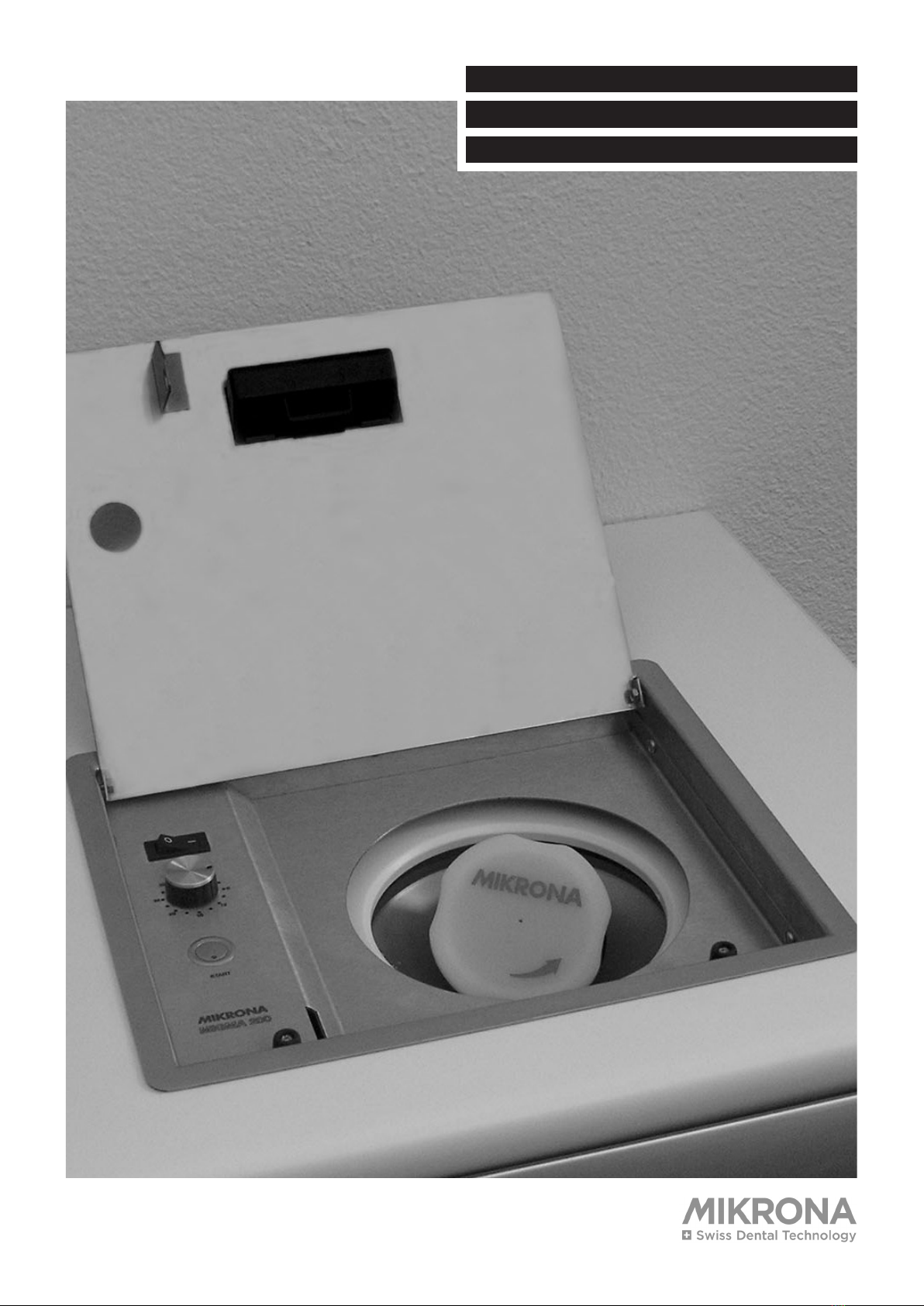
MIGMA 200-E PLANUNGS- / EINBAUANLEITUNG D
INSTRUCTIONS DE PLANIFICATION / MONTAGE
F
PLANNING / MOUNTING GUIDELINES E

2
MIGMA 200-E DEF
Einbau und Installation ..................................3
Anschlüsse (Verkabelung der Geräte) ...........4
Bedienung ......................................................5
Einbauabmessungen und
Geräteposition Möbelbreite 500mm ..............6
Einbauabmessungen und
Geräteposition Möbelbreite 350mm ..............7
Einbau ohne
Versenkung des Rahmens .............................8
Einbau mit
Versenkung des Rahmens .............................8
Mischerunterlage ...........................................8
Ausbau Bedienpanel ......................................9
Geräte-Demontage / -Montage bei
Einbau ohne Frontöffnung .............................9
Austausch
MIGMA 100-E zu
Neugerät MIGMA 200-E ...............................10
Wechsel des Bedienpanels
MIGMA 100-E zu
Neugerät MIGMA 200-E ...............................11
Wechsel des Deckels
MIGMA 100-E zu
Neugerät MIGMA 200-E ...............................11
Technische Daten .........................................12
Inhaltsverzeichnis
Informationen zur Handhabung des
Gerätes und deren Verarbeitungshinweise:
siehe Bedienungsanleitung MIGMA 200
(430.8750.01)
Mounting and installation ...............................3
Connections (cabling of devices) ..................4
Operation .......................................................5
Mounting measurements and device positio-
ning for device width 500mm ........................6
Mounting measurements and device positio-
ning for device width 350mm ........................7
Mounting without
countersinking the frame ...............................8
Mounting with
countersinking the frame ...............................8
Mixing device board .......................................8
Dismounting the service panel ......................9
Dismounting / mounting the device
without front opening .....................................9
Exchanging
MIGMA 100-E with
new device MIGMA 200-E ............................10
Exchanging the service panel
MIGMA 100-E with
new device MIGMA 200-E ............................11
Exchanging the cover
MIGMA 100-E with
new device MIGMA 200-E ............................11
Technical data ..............................................12
Montage et installation ...................................3
Raccordements (câblage des appareils) ......4
Maniement .....................................................5
Dimensions de montage et position de
l’appareil, largeur du meuble 500m ...............6
Dimensions de montage et position de
l’appareil, largeur du meuble 350mm ...........7
Montage sans
enfoncement du cadre ...................................8
Montage avec
enfoncement du cadre ...................................8
Support de mélange ......................................8
Démontage panneau de commande ............9
Démontage / montage de l’appareil en
cas de montage sans ouverture frontale .......9
Remplacement
MIGMA 100-E par
le nouvel appareil MIGMA 200-E .................10
Remplacement du panneau de commande
MIGMA 100-E par
le nouvel appareil MIGMA 200-E .................11
Remplacement du couvercle
MIGMA 100-E par
le nouvel appareil MIGMA 200-E .................11
Données techniques ....................................12
Table of contents Sommaire
For information on the device’s hand-
ling and processing see MIGMA 200 in-
struction manual (430.8750.02)
Informations supplémentaires sur le
maniement de l’appareil et ses indications
d’usinage: voir mode d’emploi
MIGMA 200 (430.8750.03)

3
DEF
1
Einbau und Installation
1. Tischabdeckung zu MIGMA 200-E in Abla-
geplatte der Möbelzeile mit Silikon einkle-
ben.
2. Einbau-Mischgerät in Möbel einschieben.
Vorgängig müssen die Transportsicherun-
gen (2 Stück) entfernt werden. Detaillierte
Informationen in der MIGMA 200 Bedie-
nungsanleitung 430.8750.01, welche dem
Gerät beigelegt ist.
3. Verkabelung des Geräts mit der Tischab-
deckung.
Anschluss ans Hausnetz (100-230V) erst
nach beendeter Montage.
Detailinformationen siehe Seite 4.
4. Mischgerät in die richtige Position
bringen
.
5. Mischgerät anheben und die Mischerun-
terlage einschieben.
Mischerunterlage dient für vereinfachtes
Herausnehmen des Mischgerät.
Detaillierte Informationen siehe Seite 8.
6. Mischgerätöffnung gegenüber der Öff-
nung der Tischabdeckung symmetrisch
ausrichten.
Das Mischgerät muss frei stehen. Keine
Berührung zu Tischabdeckung und Mö-
belseitenwände!
Abstand zu Abdeckung und Wände muss
mindestens 5mm betragen.
Gerät kann nun an das Hausnetz (100 –
230 V) angeschlossen werden.
Geräteinbetriebnahme nur in einge-
bauter Endposition. Bei Wartungen und
Demontage der Einbausituation muss das
Gerät vorgängig zwingend vom Hausnetz
(100-230V) getrennt werden!
2 3
4 5 6
Mounting and installation Montage et installation
1. Clue the table cover for MIGMA 200-E to
the worktop of the furniture using silicone.
2. Insert the built-in mixing device into the
furniture. Beforehand, remove the carriage
safety screws (2 pieces). For detailed in-
formation refer to the MIGMA 200 instruc-
tion manual 430.8750.02 which comes
with the device.
3. Cable the device with the table cover.
Do not connect the device to the mains
power supply (100-230V) before finishing
the mounting.
For detailed information refer to page 4.
4. Bring the mixing device into position.
5. Lift the mixing device and insert the mixing
device board.
This board helps to remove the mixing
device more easily.
For detailed information refer to page 8.
6. Align the opening of the mixing device
symmetrically with the table cover.
The mixing device must stand free. No
contact with table cover or furniture side
walls!
A distance of at least 5mm must be kept
to the cover and the walls.
Only use the mains power supply to con-
nect the device (100-230V)
Do not commission the device before
bringing it into its end position. It is impe-
rative to disconnect the device from the
mains power supply (100-230V) before
maintaining or dismounting any of the built-
in appliances!
Mise en service de l’appareil unique-
ment en position finale de ce dernier.
En cas de travaux de maintenance et de
démontage de l’appareil, il doit impéra-
tivement être coupé du réseau domestique
(100-230V).
1. Coller le couvercle de la table de MIGMA
200-E dans une tablette de la rangée de
meubles avec silicone.
2. Insérer l’appareil de mélange encastrable
dans le meuble. D’abord il faut enlever
les fixations de transport (2 pièces). Vous
trouverez des informations détaillées dans
le mode d’emploi 430.8750.03 de MIGMA
200 annexé à l’appareil.
3. Câblage de l’appareil avec le couvercle de
la table.
L’appareil n’est raccordé au réseau dome-
stique (100-230V) qu’après l’achèvement
du montage.
Informations détaillées voir page 4.
4. Mettre l’appareil de mélange dans la posi-
tion correcte.
5. Soulever l’appareil de mélange et insérer
le support de mélange.
Le support de mélange permet de retirer
plus facilement l’appareil de mélange. In-
formations détaillées voir page 8.
6. Orienter l’ouverture de l’appareil de
mélange symétriquement par rapport à
l’ouverture du couvercle de la table.
L’appareil de mélange doit être librement
accessible. Pas de contact avec le cou-
vercle de la table et les parois latérales du
meuble.
La distance minimale entre l’appareil et le
couvercle et les parois doit être de 5mm.
L’appareil ne peut être raccordé qu’au
réseau domestique (100-230V).

4
MIGMA 200-E DEF
Anschlüsse
(Verkabelung der Geräte)
1Hauptanschluss Hausnetz 100-230V
50/60Hz an Tischabdeckung.
2Netzverbindungsleitung zu Mischgerät
(100-230V 50/60Hz).
3Verbindungsleitung der Steuer- und Si-
cherheitseinrichtungen.
1
2
3
1Einbau in Möbelbreite 500mm
2Einbau in Möbelbreite 350mm
Geräteinbetriebnahme nur in einge-
bauter Endposition. Bei Wartungen und
Demontage der Einbausituation muss das
Gerät vorgängig zwingend vom Hausnetz
(100-230V) getrennt werden!
1 2
Do not commission the device before
bringing it into its end position. It is impe-
rative to disconnect the device from the
mains power supply (100-230V) before
maintaining or dismounting any of the built-
in appliances!
Mise en service de l’appareil unique-
ment en position finale de ce dernier.
En cas de travaux de maintenance et de
démontage de l’appareil, il doit impéra-
tivement être coupé du réseau domestique
(100-230V).
Connections
(cabling of devices)
Raccordements
(Câblage des appareils)
1Mains power supply 100-230V 50/60Hz at
table cover.
2Connection line between mains power
supply and mixing device (100-230V
50/60Hz).
3Interconnection of control and safety sy-
stem.
1Raccordement principal réseau domesti-
que 100-230V 50/60Hz au couvercle de la
table.
2Ligne électrique à l’appareil de mélange
(100-230V, 50/60Hz).
3Ligne de connexion des dispositifs de
commande et de sécurité.
1Mounting in furniture width 500mm
2Mounting in furniture width 350mm
1
Montage dans un meuble d’une largeur de 500mm
2
Montage dans un meuble d’une largeur de 350 mm
5
DEF
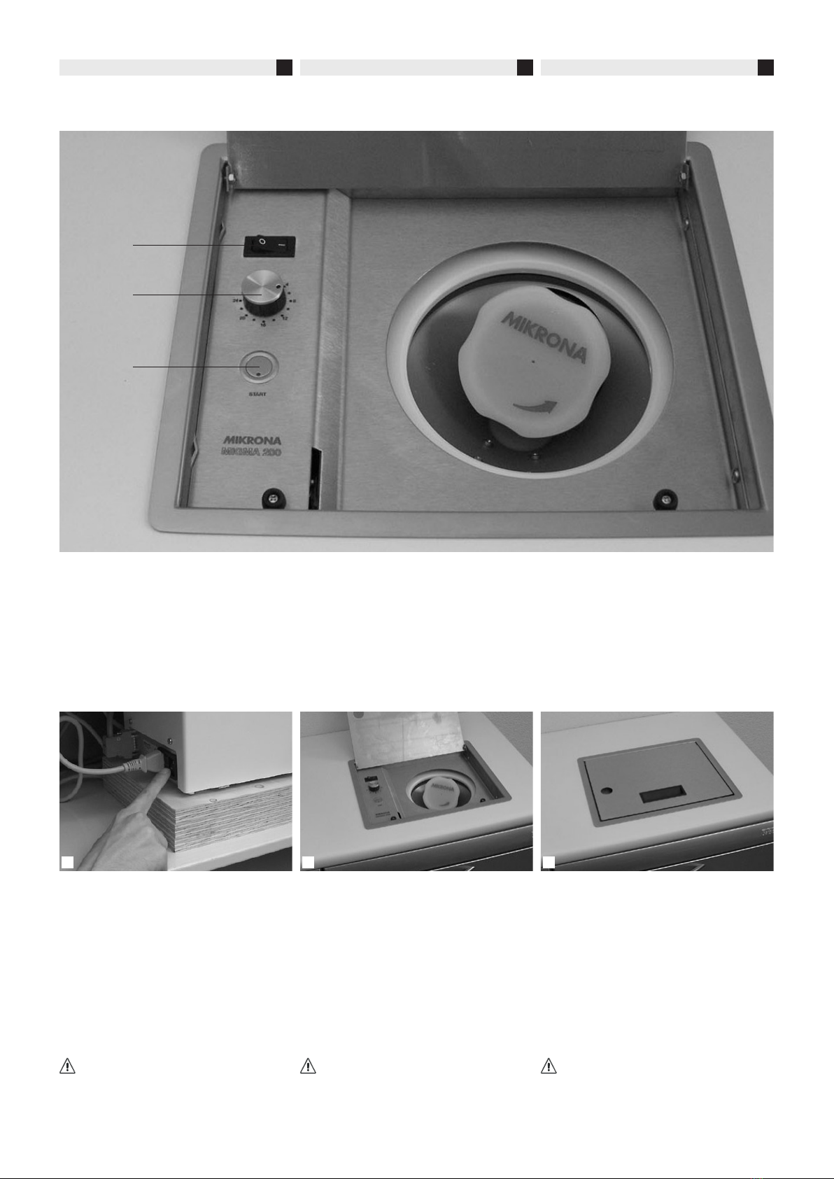
Bedienung
[1] Hauptschalter
[2] Mischzeitwähler 4 - 28 Sekunden
[3] Starttaster
1Gerätehauptschalter immer auf "ON".
Gerät wird mit Hauptschalter auf Tischab-
deckung [1] eingeschaltet.
2Hauptschalter [1] einschalten. Grüne LED
auf Starttaste [3] leuchtet. Wahl der Misch-
zeit [2] 4 - 28 Sekunden. Einsetzen des
Mischbechers mit Alginat oder anderer
Mischmasse.
3Deckel schliessen und mit Starttaste [3]
Gerät starten.
[1]
[2]
[3]
1 2 3
ManiementOperation
[1] Main switch
[2] Mixing time regulator 4 - 28 seconds
[3] Start button
[1] Interrupteur principal
[2] Sélecteur de la durée de mélange
4 - 28 secondes
[3] Touche Start
1Always keep the main switch on „ON“.
Use the main switch on the table cover [1]
to activate the device.
2Activate the main switch [1]. The LED on
the start button [3] appears green. Regu-
late the mixing time [2] 4 - 28 seconds.
Insert the mixing bowl with alginate or
another mixing compound.
3Close the cover and press the start
button [3].
1Interrupteur principal de l’appareil toujours
sur „ON“. L’appareil est mis en marche à
l’aide de l’interrupteur principal situé sur le
couvercle de la table [1].
2Activer l’interrupteur principal [1]. La LED
verte [3] est allumée. Sélection de la
durée de mélange [2] 4 - 28 secondes.
Insérer le bol de mélange avec alginate ou
une autre masse de mélange.
3Fermer le couvercle et mettre l’appareil en
marche avec la touche Start [3].
Informationen zur Handhabung des
Gerätes und deren Verarbeitungshinweise:
siehe Bedienungsanleitung MIGMA 200
(430.8750.01)
For information on the device’s hand-
ling and processing see MIGMA 200 in-
struction manual (430.8750.02)
Informations supplémentaires sur le
maniement de l’appareil et ses indications
d’usinage: voir mode d’emploi
MIGMA 200 (430.8750.03)
6
MIGMA 200-E DEF
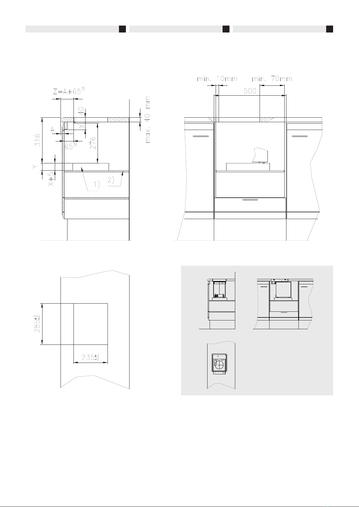
Einbauabmessungen und Geräteposition
Möbelbreite 500mm
3) Mass kann bei Möbelzeilenbreite 500mm
reduziert werden.
Mindestabstand: 40mm
2) Tragkraft der Platte oder des Einschubs
muss für ein Gerätegewicht von 20kg aus-
gelegt sein.
1) Mischerunterlage für vereinfachtes Her-
ausnehmen des Mischgerätes (siehe
Seite 8).
Mindestgrösse der Unterlage:
300 x 250 x Y mm
3) The Measurement can be reduced if the
furniture width is 500mm.
Minimal distance: 40mm
2) The worktop and the board must have a
minimal load capacity of 20kg.
1) Mixing device board for easy removal of
the mixing device (see page 8).
Minimal board size:
300 x 250 x Y mm
Mounting measurements and device posi-
tioning for device width 500mm
Dimensions de montage et position de
l’appareil, largeur du meuble 500mm
3) La largeur de la rangée de meubles de
500mm permet de réduire la dimension.
Distance minimale: 40mm.
2) La force portante de la plaque ou de
l’élément enfichable doit être conçue pour
un poids de l’appareil de 20kg.
1) Support de mélange pour retirer plus fa-
cilement l’appareil de mélange (voir page
8).
Dimensions minimales du support:
300 x 250 x Y mm
7
DEF
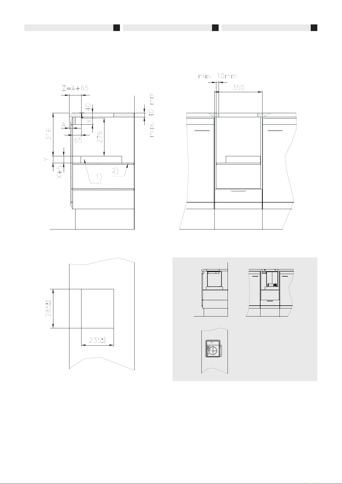
Einbauabmessungen und Geräteposition
Möbelbreite 350mm
2) Tragkraft der Platte oder des Einschubes
muss für ein Gerätegewicht von 20kg aus-
gelegt sein.
1) Mischerunterlage für vereinfachtes Her-
ausnehmen des Mischgerätes (siehe
Seite 8).
Mindestgrösse der Unterlage:
300 x 250 x Y mm
Mounting measurements and device posi-
tioning for device width 350mm
2) The worktop and the board must have a
minimal load capacity of 20kg.
1) Mixing device board for easy removal of
the mixing device (see page 8).
Minimal board size:
300 x 250 x Y mm
Dimensions de montage et position de
l’appareil, largeur du meuble 350mm
2) La force portante de la plaque ou de
l’élément enfichable doit être conçue pour
un poids de l’appareil de 20kg.
1) Support de mélange pour retirer plus fa-
cilement l’appareil de mélange (voir page
8).
Dimensions minimales du support:
300 x 250 x Y mm
8
MIGMA 200-E DEF
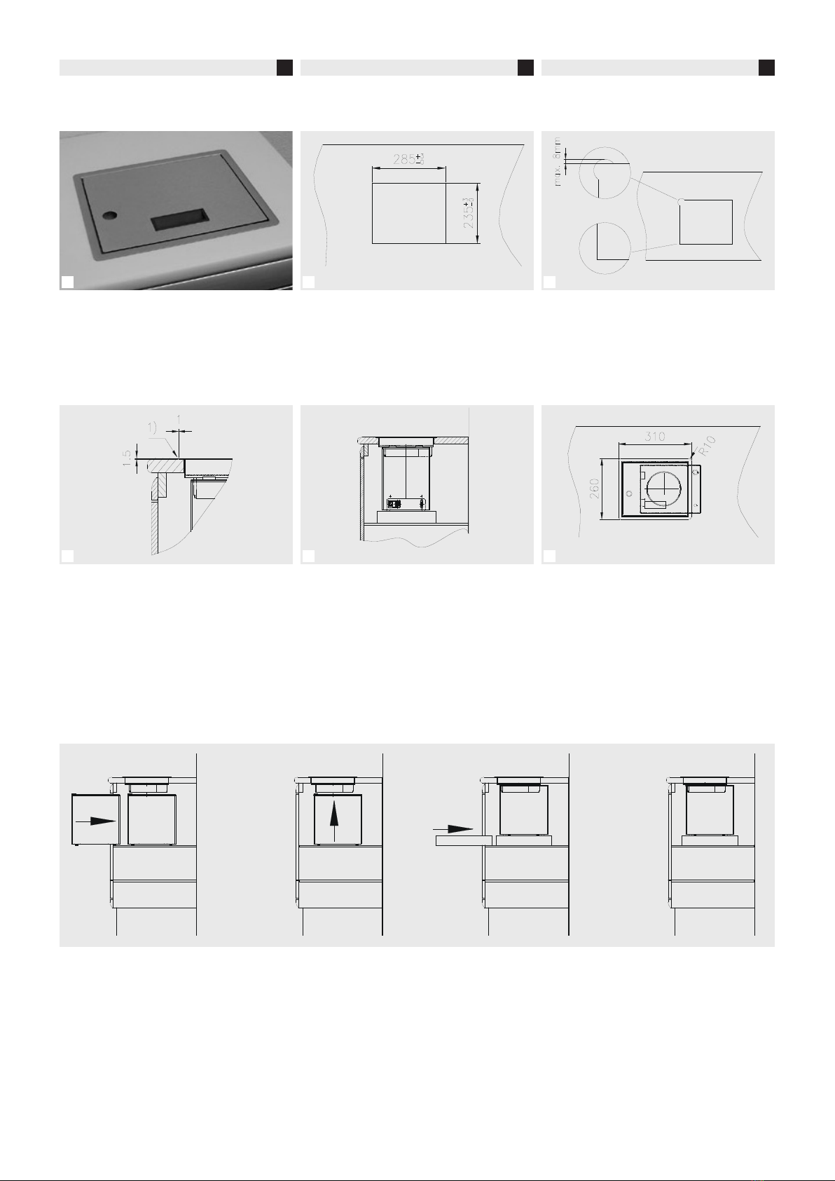
Einbau ohne Versenkung des Rahmens
1Tischabdeckung mit Silikon einkleben.
2Tischplattenöffnung 235 x 285mm
3Ausschnitt scharfkantig oder positive
Rundung (maximal 8mm gösser als Basi-
sauschnitt).
Einbau mit Versenkung des Rahmens
1Versenken des Rahmens auf Tischplatten-
höhe (Rahmendicke 1,5mm)
1) Silikonfuge ca. 1mm
2Tischplatte und Arbeitsplatte haben die
gleiche Höhe.
3Rahmengrösse 310 x 260 mm.
Zugabe für Silikonfuge von ca. 1mm je
nach gewählter Einbautechnik.
Mischerunterlage
Mischerunterlage dient für vereinfachtes Her-
ausnehmen des Mischgerät. Je nach Möbel-
konstruktion müsste ansonsten die Auflage-
platte verstellbar sein oder das Gerät muss bei
Wartungsarbeiten durch die Tischabdeckung
entfernt werden.
Mindestgrösse der Mischerunterlage:
300 x 250 x Y mm
Höhe Y muss nach Möbelblende und Position
der Auflageplatte ausgelegt werden.
1 2 3
1 2 3
Mounting without countersinking the frame
Montage sans enfoncement du cadre
1Clue the table cover using silicone.
2Opening of worktop 235 x 285mm
3Cut it out with sharp edges or with positive
rounding (max 8mm larger than basic
cut).
Mounting with countersinking the frame Montage avec enfoncement du cadre
1Countersink the frame to the level of the
worktop (frame thickness 1.5mm),
1) silicone joint of approx. 1mm
2Table cover and worktop are at the same
level.
3Frame size 310 x 260 mm.
Depending on the mounting technique,
add approx. 1mm for the silicone joint.
Mixing device board
This board serves to remove the mixing device
more easily. Depending on the construction
of the furniture, the worktop would otherwise
need to be adjustable or
the device would have to be removed for
maintenance work.
Minimal size of the mixing device board:
300 x 250 x Y mm.
The height Y must be laid out according to the
furniture end and the position of the worktop.
1
Coller le couvercle de la table avec silicone.
2
Ouverture du plateau de table 235 x 285mm
3Coupe à vive arête ou arrondissage positif
(max. 8 mm plus grand que la coupe de
base).
1Enfoncement du cadre à la hauteur du
plateau de table
(épaisseur du cadre 1,5 mm)
1) joint silicone env. 1mm
2Le plateau de table et la plaque de travail
ont la même hauteur.
3Dimension du cadre: 310 x 260 mm.
Addition d’environ 1 mm pour le joint
silicone en fonction de la technique de
montage choisie.
Support de mélange
Le support de mélange permet de retirer plus
facilement l’appareil de mélange. Sinon, la
plaque de support devrait être réglable en
fonction de la construction du meuble ou l’ap-
pareil doit être enlevé à travers le couvercle de
la table lors des travaux de maintenance.
Dimensions minimales du support de mélan-
ge: 300 x 250 x Y mm.
La hauteur Y doit être conçue en fonction du
bandeau du meuble et la position de la plaque
de support.
9
DEF
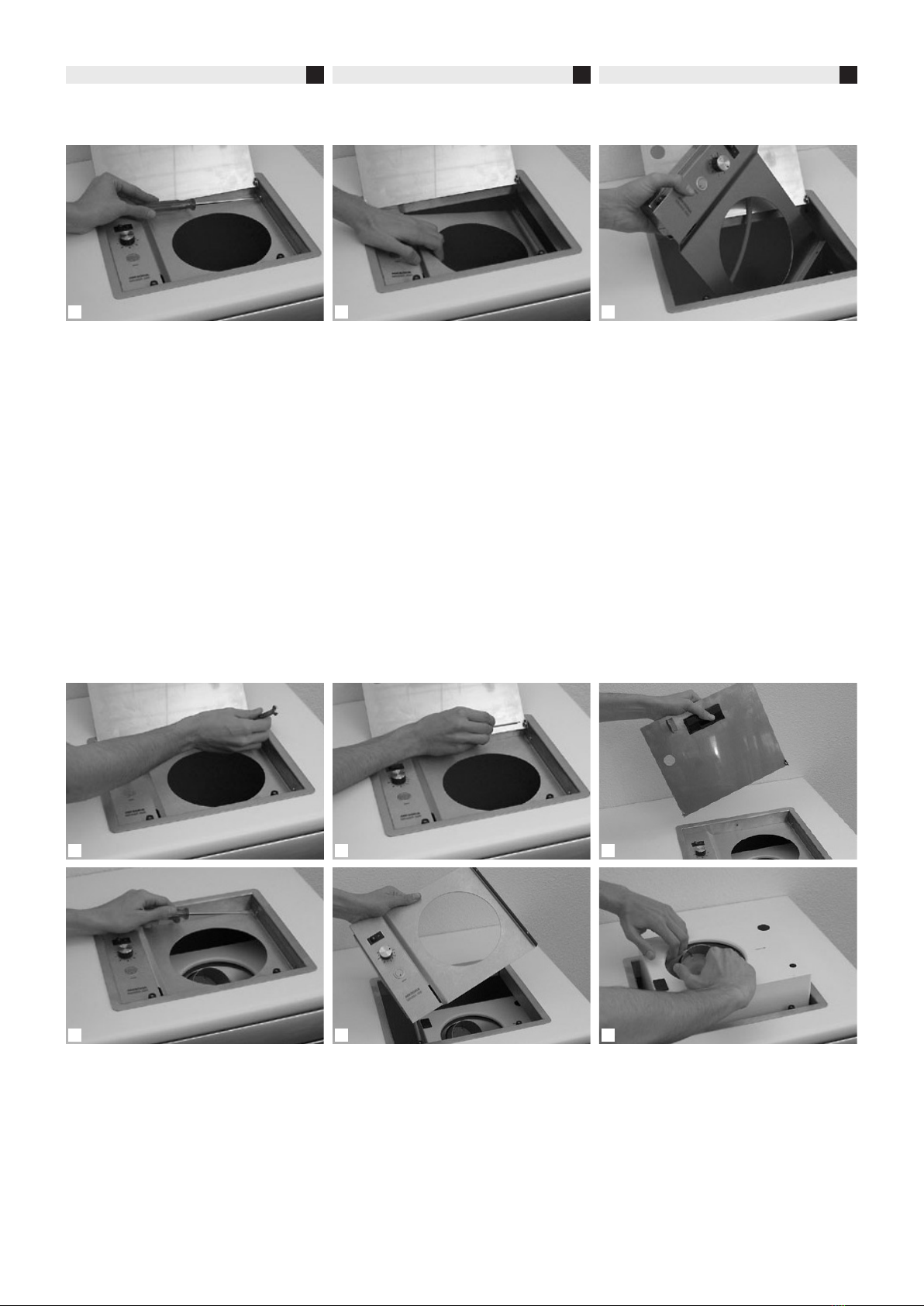
Ausbau Bedienpanel
1Die beiden Befestigungsschrauben lösen
und entfernen.
2Bedienpanel rechts nach unten schwen-
ken und aus der linken Aufnahmevorrich-
tung ziehen.
3Bedienpanel abdrehen und durch die Öff-
nung herausziehen.
Geräte-Demontage / -Montage bei Einbau
ohne Frontöffnung
1Kontermutter rechts und links am Schar-
nier lösen.
2Scharnierachse beidseitig heraus-
schrauben.
3Deckel entfernen.
4Panelbefestigungsschrauben lösen und
entfernen.
5Bedienpanel entfernen.
6Gerät durch die Öffnung entfernen.
1 2 3
1 2 3
4 5 6
Dismounting the service panel Démontage panneau de commande
1Release and remove the two attachment
screws.
2Push the service panel down on the right
side and release it from the retainer on the
left.
3Turn the service panel and take it out
through the opening.
1Dévisser et retirer les deux vis de fixation.
2Pivoter le panneau de commande à droite
vers le bas et retirer du dispositif de récep-
tion.
3Deviser le panneau de commande et reti-
rer à travers l’ouverture.
Dismounting / mounting the device without
front opening
Démontage / montage de l’appareil en cas
de montage sans ouverture frontale
1Release the counter nut at the hinge on
the right and the left.
2Remove the hinge axis on both sides.
3Remove the cover.
4Release and remove the two attachment
screws.
5Remove the service panel.
6Take out the device through the opening.
1Dévisser le contre-écrou à droite et à gau-
che de la charnière.
2Dévisser l’axe de charnière des deux cô-
tés.
3Enlever le couvercle.
4Dévisser et retirer les vis de fixation du
panneau.
5Retirer le panneau de commande.
6Retirer l’appareil à travers l’ouverture.
10
MIGMA 200-E DEF
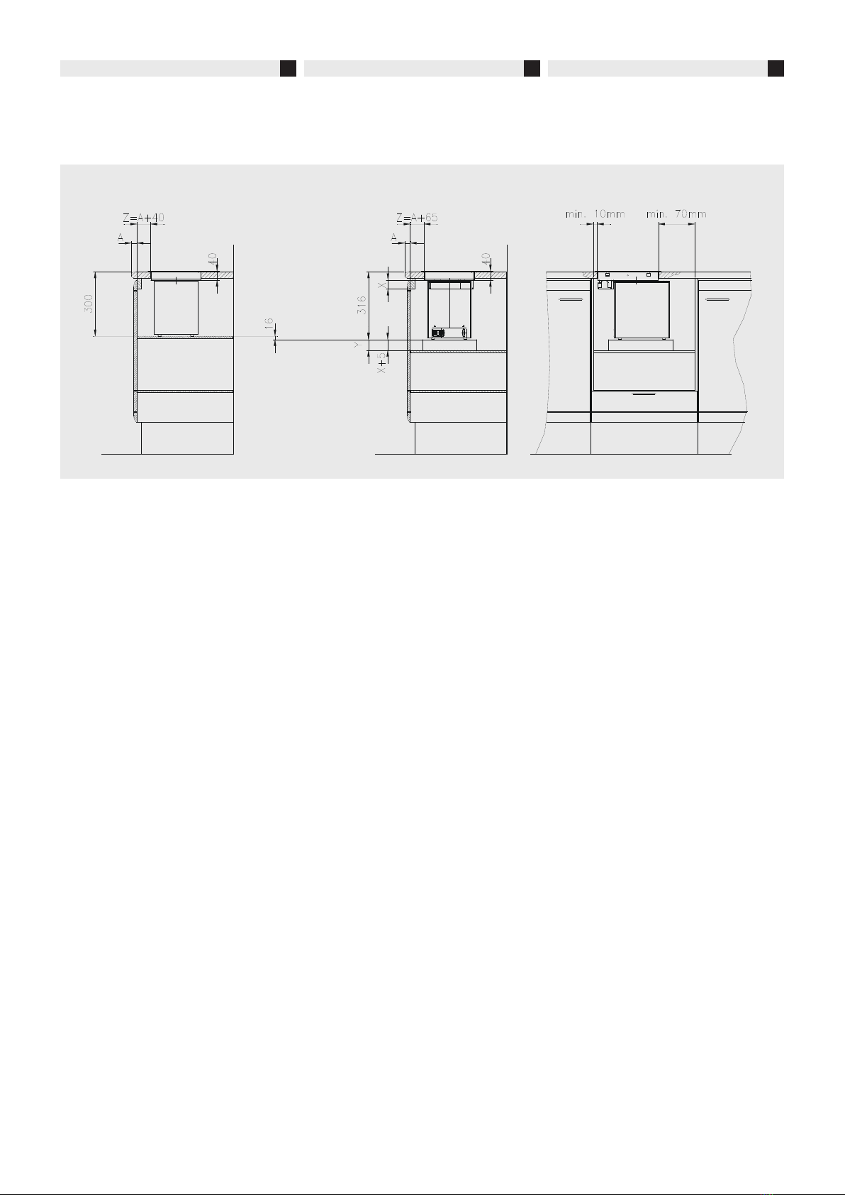
Austausch MIGMA 100-E
zu Neugerät MIGMA 200-E
MIGMA 200-E ist 16 mm höher als das
Vorgängergerät MIGMA 100-E.
Tablar oder Schrankboden muss um
16 mm tiefer gesetzt werden können.
Der Abstand von der Tischkante bis Ein-
bauloch empfehlen wir bei MIGMA 200-E
+25mm gegnüber dem Vorgängermodell.
bei Möbelbreite 500 mm kann das
empfohlene Einbaumass von 65 mm
auf 45 mm reduziert werden, wenn
das Minimalmass zur Seitenwand
eingehalten werden kann.
Einbau wie Vorgängermodell!
Der Rahmen, der im TIschblatt eingelegt
wird, ist bei beiden Modellvarianten der
gleiche.
Somit ist auch die Aussparung im
Tischblatt gleich gross.
Beim Austausch eines Einbau-
mischers zu einem MIGMA 200-E
kann der Rahmen im Tischblatt weiter
verwendet werden. Ausgewechselt
werden muss der Deckel und das
Bedienpanel.
MIGMA 100-E MIGMA 200-E
Exchanging MIGMA 100-E
with new device MIGMA 200-E
Remplacement MIGMA 100-E
par le nouvel appareil MIGMA 200-E
MIGMA 200-E is 16 mm higher than its
predecessor MIGMA 100-E.
The shelf or the cupboard floor must
be lowered by 16 mm.
We recommend increasing the distance
between table-edge and mounting hole by
+25 mm compared to the former measu-
res.
With a furniture width of 500 mm,
the recommended mounting distance
of 65 mm can be reduced to 45 mm if
the minimal distance to the side wall
can be kept.
Same mounting as predecessor!
The size of the frame that is inserted in the
worktop remains the same.
Therefore, the size of the opening
remains the same as well.
You can continue using the same
frame in the worktop that has been
used for a built-in mixing device when
changing to MIGMA 200-E. You need,
however, to replace the cover and the
service panel.
MIGMA 200-E est 16 mm plus haut que
l’appareil précédent MIGMA 100-E.
Le tablard ou le fond de l’armoire doit
pouvoir être abaissé de 16 mm.
Nous recommandons pour le MIGMA
200-E une distance entre le bord de la ta-
ble et le trou de montage de +25 mm par
rapport au modèle précédent.
Si la largeur du meuble est de
500 mm, la dimension de montage
recommandée peut être réduite
de 65 mm à 45 mm lorsque la dimen-
sion minimale à la paroi latérale peut
être respectée.
Montage à l’instar du modèle précédent!
Le cadre inséré au plateau de table est le
même pour les deux modèles.
Ainsi, le creux dans le plateau de tab-
le présente les mêmes dimensions.
Lors de l’échange d’un appareil de
mélange encastrable par un
MIGMA 200-E, le cadre du plateau de
table peut être réutilisé. Le couvercle
et le panneau de commande doivent
être remplacés.

11
DEF
1 2 3
1 2 3
Wechsel des Bedienpanels
MIGMA 100-E
zu Neugerät MIGMA 200-E
1Bedienpanel MIGMA 100-E entfernen und
neuen Bedienpanel MIGMA 200-E einfü-
gen.
2Einhängen der Platte in die Haltevorrich-
tung auf der linken Seite des Rahmens.
Panel von unten nach oben einklappen.
3Befestigung der Platte mit zwei Schrauben
auf der rechten Seite.
Wechsel des Deckels
MIGMA 100-E
zu Neugerät MIGMA 200-E
1Deckel MIGMA 100-E entfernen und
neuen Deckel MIGMA 200-E einsetzen.
2Scharnierschraube rechts und links ein-
setzen.
Einstellen der Deckelposition mit Hilfe der
Positions- und Kontermutter.
3Festziehen der Kontermutter am rechten
und linken Scharnier.
Exchanging the service panel
MIGMA 100-E
with new device MIGMA 200-E
Remplacement du panneau de commande
MIGMA 100-E
par le nouvel appareil MIGMA 200-E
1Remove the service panel MIGMA 100-E
and replace it with the new service panel
MIGMA 200-E.
2Fit the panel into the retainer on the left
side of the frame and pull it up to engage
it.
3Attach the panel with two screws on the
right side.
1Retirer le panneau de commande MIGMA
100-E Insérer le nouveau panneau de
commande MIGMA 200-E.
2Accrocher la plaque dans le dispositif de
support sur le côté gauche du cadre.
Rabattre le panneau du bas vers le haut.
3Fixation de la plaque à l’aide de deux vis
sur le côté droite.
Exchanging the cover
MIGMA 100-E
with new device MIGMA 200-E
Remplacement du couvercle
MIGMA 100-E
par le nouvel appareil MIGMA 200-E
1Remove the cover MIGMA 100-E and re-
place it with the new cover
MIGMA 200-E.
2Insert the hinge screw on the left and the
right and adjust the position of the cover
with the positioning and counter nut.
3Tighten up the counter nut at the right and
left hinge.
1Retirer le couvercle MIGMA 100-E et
insérer le nouveau couvercle
MIGMA 200-E.
2Insérer la vis de charnière à droite et à
gauche.
Régler la position du couvercle à l’aide
d’un écrou de position et un contre-écrou
3Serrer le contre-écrou à la charnière droite
et gauche.

12
MIGMA 200-E DEF
Technische Daten
Tischabdeckung
Abmessung (cm) BxTxH ............31 x 26 x 8,5
Material ....................................................Inox
Gewicht netto (kg) .....................................2,8
Artikel-Nr. .....................................430.6103.01
Einbau Mischgerät
Abmessung (cm) BxTxH ....25,8 x 20,3 x 27,7
Gewicht netto (kg) ...................................17,1
Farbe ...............................................RAL 9003
Drehzahl (min-1)......................................2'800
Artikel-Nr. .....................................430.6102.01
Elektrischer Anschluss
Spannung (VAC) ............................. 100 - 230
Frequenz (Hz)...................................... 50 / 60
Leistung (W) ..............................................250
Einschaltdauer......................................... 15%
Sicherung ...........................................2 x 4 AT
Transportverpackung
Abmessung (cm) BxTxH .............45 x 29 x 50
Gewicht netto (kg) ...................................19,9
Gewicht brutto (kg) ..................................23,1
Bestellnummer
430.6505.01 Universal Mischgerät
MIGMA 200-E
Netzstecker Typ A (Schuko)
430.6505.02 Universal Mischgerät
MIGMA 200-E
Netzstecker Typ L (Schweiz)
430.6505.03 Universal Mischgerät
MIGMA 200-E
Netzstecker Typ K (US)
430.6505.04 Universal Mischgerät
MIGMA 200-E
Netzstecker Typ D (GB)
Technical data
Table cover
Dimensions (cm) WxDxH .......... 31 x 26 x 8,5
Material ....................................................Inox
Net weight (kg) ..........................................2,8
Article no. ....................................430.6103.01
Mounting of mixing device
Dimensions (cm) WxDxH .. 25,8 x 20,3 x 27,7
Net weight (kg) ........................................17,1
Color ..............................................RAL 9003
Revolutions (min-1) .................................2’800
Article no. ....................................430.6102.01
Electrical connection
Voltage (VAC) ................................. 100 - 230
Frequency (Hz) ................................... 50 / 60
Power (W) .................................................250
Duty rate ................................................. 15%
Fuse protection ..................................2 x 4 AT
Transport packaging
Dimensions (cm) WxDxH ........... 45 x 29 x 50
Net weight (kg) ........................................19,9
Gross weight (kg) ....................................23,1
Order number
430.6505.01 Universal mixing device
MIGMA 200-E
power plug type A (Schuko)
430.6505.02 Universal mixing device
MIGMA 200-E
power plug type L (Schweiz)
430.6505.03 Universal mixing device
MIGMA 200-E
power plug type K (US)
430.6505.04 Universal mixing device
MIGMA 200-E
power plug type D (GB)
Données techniques
Couvercle de la table
Dimension (cm) LxPxH............... 31 x 26 x 8,5
Matériel .....................................................Inox
Poids net (kg)..............................................2,8
Numéro d'article...........................460.6103.01
Montage appareil de mélange
Dimension (cm) LxPxH....... 25,8 x 20,3 x 27,7
Poids net (kg)............................................17,1
Couleur ............................................RAL 9003
Vitesse (min-1).........................................2'800
Numéro d'article...........................430.6102.01
Raccord électrique
Tension (VAC) .................................. 100 - 230
Fréquence (Hz).................................... 50 / 60
Puissance (W)............................................250
Durée de mise en service........................ 15%
Fusible.................................................2 x 4 AT
Emballage de transport
Dimension (cm) LxPxH................ 45 x 29 x 50
Poids net (kg)............................................19,9
Poids brut (kg)..........................................23,1
Numéro de commande
430.6505.01 Appareil de mélange universel
MIGMA 200-E
cordon électrique type A (Schuko)
430.6505.02 Appareil de mélange universel
MIGMA 200-E
cordon électrique type L (Schweiz)
430.6505.03 Appareil de mélange universel
MIGMA 200-E
cordon électrique type
K (US)
430.6505.04 Appareil de mélange universel
MIGMA 200-E
cordon électrique type
D (GB)
MIKRONA TECHNOLOGIE AG Wigartestrasse 8 | 8957 Spreitenbach | Switzerland
Table of contents
Other Mikrona Dental Equipment manuals


