Mikroskop Technik Rathenow RMA 5 User manual
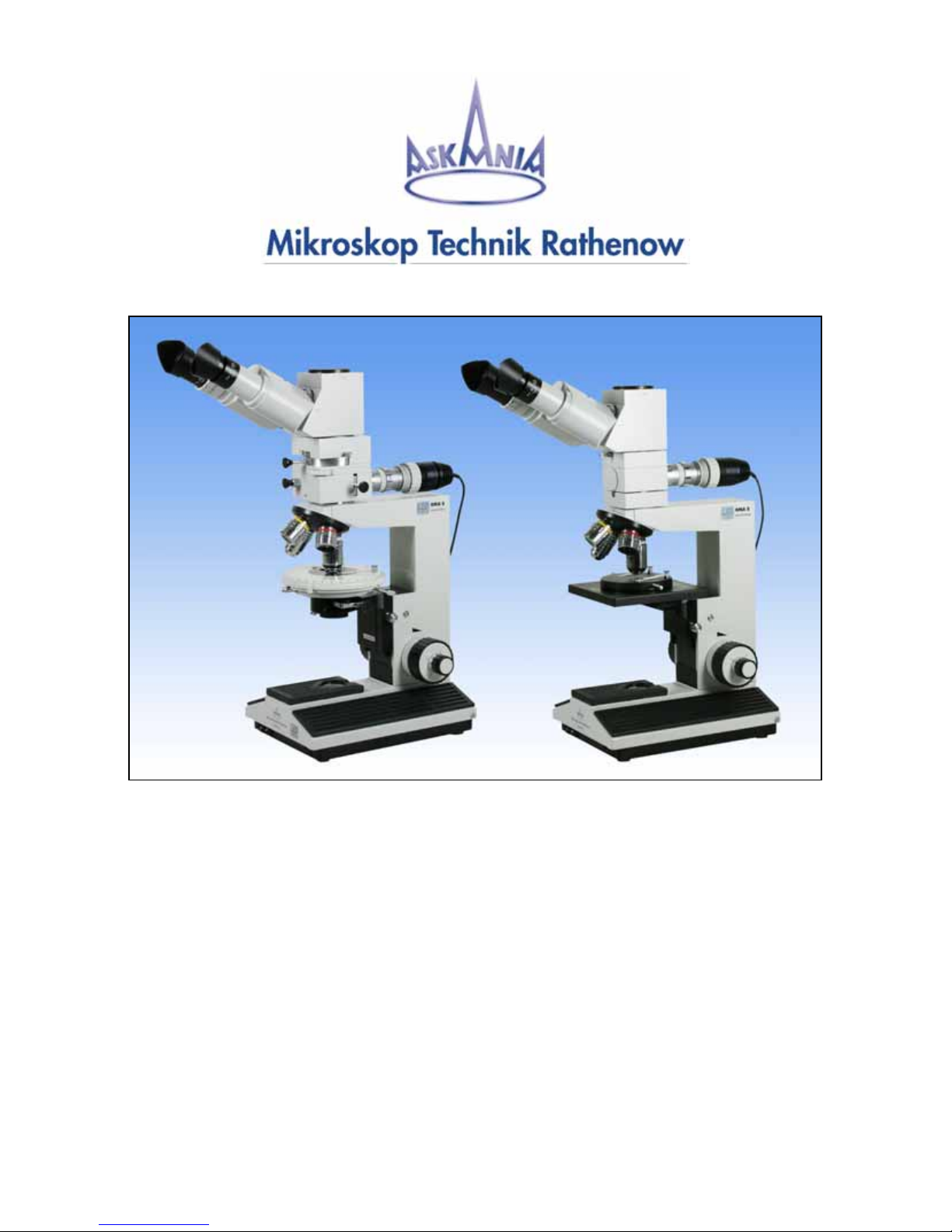
Polarization Microscope - RMA 5 pol
Technical Incident Light Microscope - RMA 5
User Guide


3
Table of contents
1. Safety Instructions
1.1. Characteristics and Applications……………………………………………..5
1.2. Assembly and Operation RMA 5 pol….……………………………………. 6
1.3. Technical Data RMA 5 pol…………………………………………………. 7
1.4. Assembly and Operation RMA 5……………………………………………. 8
1.5. Technical Data RMA 5………………………………………………………. 9
2. Starting Operations
2.1 Assembly……………………………………………………………………… 10
2.2 Adjusting the sharpness……………………………………………………….10
2.3. Incident light illumination………………………………………………………11
2.4 Polarization units………………………………………………………………11
2.4.1 Incident light polarization………………………………………… 11
2.4.2 Transmitted light polarization…………………………………….. 12
2.4.3 Compensator………………………………………………………12
2.5. General Operating Instructions……………………………………………….13
2.5.1. Vertical adjustment of the Microscope……………………………13
2.5.2 Optimising the illumination………………………………………..13
2.5.3 Changing the tubes………………………………………………. 13
2.5.4. Changing the objectives…………………………………………. 13
2.5.5. Changing the eyepieces…………………………………………. 13
3. Maintenance and Service
3.1. Changing the fuse……………………………………………………………. 14
3.1.1. RMA 5……………………………………………………………..14
3.2. Care of components………………………………………………………… 14
3.2.1. Dioptre rings……………………………………………………….14
3.2.2. Eyepieces, Tubes and Objectives……………………………….. 14
3.2.3. Microscope………………………………………………………..14
3.2.4. Gliding stage…………………………………………………….. 14
4. Supplementary Equipment
4.1. Eyepieces…………………………………………………………………….. 15
4.1.1. Fixed eyepieces………………………………………………….. 15
4.1.2. Adjustable eyepieces……………………………………………..15
4.2. Tubes…………………………………………………………………………..15
4.2.1. Monocular straight tube …………………………………………. 15
4.2.2. Binocular straight tube……………………………………………. 15
4.3. Objectives……………………………………………………………………. 16
4.4. Color filter……………………………………………………………………..16

4
5. Intermediate Tubes
5.1. Angled tube…………………………………………………………………...16
5.2. Photo-/TV tube……………………………………………………………….. 16
5.3. Wide field Photo Tube for M-Plan objectives……………………………….. 17
6. Measuring instruments
6.1. Eyepiece with measuring plate……………………………………………….17
6.2. Object measuring plate……………………………………………………….17
6.3. Measuring software………………………………………………………….. 17
7. Documentation
7.1. Photography over Photo-/TV tube…………………………………………… 18
7.2. Digital photography………………………………………………………….. 18
8. TV – Transfer
8.1. TV-Transfer over Photo-/TV tube……………………………………………..19
8.1.1. TV – Adapter 1,0x……………………………………………….. 19
8.1.2 TV - Adapter 0,3x; 0,4x; 0,4xWF; 0,63x; 1,6x….…………. 19
9. Illumination
9.1. 3W-LED transmitted light…………………………………………………….. 20
9.2. Oblique incident light (dark field)…………………………………………….20
10. Stages
10.1. Gliding stage………………………………………………………………….21
10.2. Stage carrier with object guide……………………………………………… 21
10.3. Stage carrier with rotary stage………………………………………………. 21
10.4. Magnet spherical stage……………………………………………………… 21
10.5 Depth measurement………………………………………………………….. 22
10.5.1 with combination drive……………………………………………22
10.5.2 with coaxial coarse and fine drive……………………………….22
10.5.3 with dial indicator gauge…………………………………………22
11. System overview………………………………………………………………23
12. Complaints, Warranty………………………………………………………..24

5
1. Safety Instructions
CAUTION! Please read the following
information carefully before using the unit and its
supplementary equipment!
This unit was constructed and checked
according to the safety regulations for electronic
measuring devices, and was delivered securely.
This User Manual contains information and
warning notices that should be heeded by the
user.
The unit is a light microscope, drafted according
to the newest scientific and technical knowledge
for the visual, micro photographic and video-
technical investigation of microscopic objects.
The unit should only be used for the designed
purpose. All other uses (also the insertion of
single components which were not designed by
the manufacturer) constitute a misuse of the
product. We are not liable for any damages
caused by this misuse.
This unit is not meant for unattended continuous
operation.
The microscope does not have any special
safeguards against samples with caustic toxic,
radioactive or other hazardous materials. The
allowed sample amount may not be exceeded.
The unit may only be operated on the voltages
indicated on the unit. Please heed the
instructions in the user manual! We are not liable
for any damages caused by the disregard of
these instructions.
If the unit is connected to voltage, contact
clamps can lead to dangerous voltages and
opening the coverings or removing parts can
uncover a piece under a dangerous voltage.
The unit must be disconnected from power
before it can be opened for adjustments,
replacements, servicing or repairs.
Existing ventilation slits should not be obstructed.
This also applies for ventilation slits on the
bottom of the unit. No tools, loose objects or
liquids should enter the unit through ventilation
slits or other openings in the unit.
Only fuses with the required nominal current may
be used as substitutes for the prescribed use. It is
prohibited to use makeshift fuses or short-circuit
the fuse support.
If safety is endangered , the unit must be
removed from use and secured against
unattended operation. The unit should then be
sent to the production factory or a competent
service technician.
Before switching on the unit, set the controller for
the illumination intensity to the left catch in order
to prevent blinding.
1.1. Characteristics and Application
The microscope RMA 5 is equipped with high
quality optics, and excels due to its high optical
performance.
The following additional devices are available:
evaluation of investigations over Photo-/TV
adapter and digital cameras, Polarization
equipment, measuring software...
Different interchangeable objectives and
eyepieces, which can be changed easily by a
revolver (quadruple), make an extension area in
an interval of 50x ... 640x possible (standard
configuration).
6
1.2. Assembly and Operation RMA 5 pol
The polarization microscope RMA 5 pol comes
with a fixed stand. All further components of the
microscope are mounted on this stand. There is
a pol.-suited binocular straight tube with wide
field eyepieces (spectacles) for a research of
objects.
The microscope RMA 5 pol is assembled with a
revolving nosepiece (quadruple) and four M-Plan
∞objectives.. The ball bearing revolver has click
stops for the positions of each objective.
There are three stages for fixing the objects
under the microscope (gliding stage, stage
carrier with object guide and stage carrier with
rotary stage). The objects will be illuminated by
a 3W-LED incident light or transmitted light
illumination (Koehler principle).
All electronic parts for the illumination are
integrated into the microscope base. There is a
control for adjusting the illumination in front and
on the side of the microscope base. It is also
possible to add other kind of illuminations to the
microscope (transmitted light illumination, striped
incident light).
Further information, how polarization microscopy
is working, you can find in special literature.
We will describe only necessary features of the
microscope RMA 5 pol at the following pages.
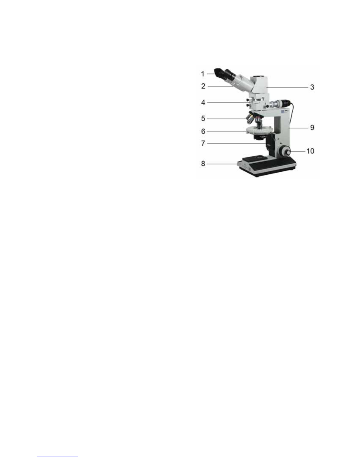
Polarization Microscope RMA 5 pol
pic.1: overview RMA 5 pol
1 Eyecup with eyepiece
2 Binocular straight tube
3 Angled tube / photo /TV tube 1x/0,8x
4 Incident light polarization tube
5 Revolving nosepiece with objectives
6 Microscope stage
7 Stage holder
8 Microscope base
9 Microscope stand
10 Coaxial coarse and fine drive adjustment

7
1.3. Technical Data RMA 5 pol
With Semi- Apochromat ∞Objectives (standard)
Objective (incident light) M-Plan ∞
5x; 10x; 20x; 50x
Eyepiece GF-Pw 10x/ 20
Tube factor 1x Visuell
0,8x photo/TV
Illumination
Koehler principle with filter holder,
field diaphragm and aperture diaphragm
Total magnification
Vt = Vobj x Veyep 50x ... 500x
Object field (mm) 4,0... 0,4
Adjustable range of coarse drive 20 mm
Max. High of objects 35 mm
Interpupillary adjustment 55...80 mm
Adjustment ametropia +/- 6 dpt
Adjustment Object-guide 40 mm x 20 mm
Adjustment Gliding stage d = 40 mm
Coaxial coarse and fine drive
Resolution 2 µm
8
1.4. Assembly and Operation RMA 5
The incident light microscope RMA 5 comes with
a fixed stand. All further components of the
microscope are mount on this stand. There is a
binocular straight tube with wide field eyepieces
(spectacles) for a research of objects.
The microscope RMA 5 is assembled with a
revolving nosepiece (quadruple) and four M-Plan
∞objectives. Alternative you can use achromatic
corrected objectives and semi plan achromatic
objectives for a mechanical tube length of
160mm. The ball bearing revolver has click
stops for the positions of each objective.
There are four stages for fixing the objects under
the microscope (gliding stage, magnet spherical
stage, stage carrier with object guide and stage
carrier with rotary stage). The objects will be
illuminated by a 3W-LED incident light
illumination (Koehler principle).
All electronic parts for the illumination are
integrated into the microscope base. There is a
control for adjusting the illumination in front of
the microscope base. It is also possible to add
other kind of illuminations to the microscope
(transmitted light illumination, striped incident
light).
Further information, how a incident light
microscope is working, you can find in special
literature.
We will describe only necessary features of the
microscope RMA 5 at the following pages.
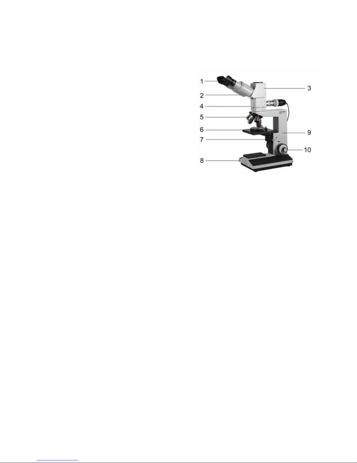
Technical – Incident Light Microscope RMA 5
pic.2: overview RMA 5
1 Eyecup with eyepiece
2 Binocular straight tube
3 Angled tube
4 Incident light tube
5 Revolving nosepiece with objectives
6 Microscope stage
7 Stage holder
8 Microscope base
9 Microscope stand
10 Combined Coaxial coarse and fine
drive adjustment

9
1.5. Technical Data RMA 5
Microscope: E-Plan ∞Objectives
Objectives (incident light) M-Plan ∞
5x; 10x; 20x; 50x
Eyepiece GF-Pw 10x/ 20
Tube Factor 1x
Illumination
Koehler principle with filter holder,
field diaphragm and aperture diaphragm
Total magnification
Vt = Vobj x Veyep 50x ... 500x
Object field (mm) 4,0... 0,4
Adjustable range of coarse drive 15 mm
Max. High of objects 35 mm
Interpupillary adjustment 55...80 mm
Adjustment ametropia +/- 6 dpt
Adjustment Object-guide 76 mm x 26 mm
Adjustment Gliding stage d = 40 mm
Coaxial coarse and fine drive
Resolution 2 µm
Microscope: Achromatic 160mm Objectives
Objectives
4x; 10x; 20x; 40x
Eyepiece GF 10x/ 18
Tube Factor 1,6x
Illumination Koehler principle with filter holder,
field diaphragm and aperture diaphragm
Total magnification
Vt = Vobj x Veyep 64x... 640x
Object field (mm) 2,8... 0,28
Adjustable range of coarse drive 15 mm
Max. High of objects 35 mm
Interpupillary adjustment 55...80 mm
Adjustment ametropia +/- 6 dpt
Adjustment Object-guide 76 mm x 26 mm
Adjustment Gliding stage d = 40 mm
Combination drive
Resolution 2,8 µm

10
2. Starting Operations
2.1. Assembly
Please open carefully the packaging of the
microscope.
At first the microscope stand (10) has to be
taken out of the packaging and has to be put on
a plan subsoil. After that the incident light tube
(4) has to be set on the quick-change equipment
of the microscope stand. Clamp it with the
screw.
The binocular straight tube (2) and the angled
tube (3) has to be taken from the packaging.
Assemble the binocular straight tube into the
quick-change equipment of the angled tube and
clamp it with a screw.
Take this pre-assembled parts and set them to the
quick-change equipment of the incident light tube
and clamp it with the screw.
Now the objectives will be taken out of their
protective packaging and the objectives has to
be placed into the revolving nosepiece (5) in
this way, that if the revolver will be rotated
clockwise, the magnification will be increase.
The stage (gliding stage, stage carrier with
object guide or stage carrier with rotary table)
will be done into the stage holder (7) and will
be clamped. The adjustment of the objectives
will be done by the combined coaxial coarse
and fine drive adjustment (9).
At last the eyepieces GF – Pw 10x/20 (1) will
be assembled into the binocular straight tube.
The eyepiece can be used with or without
eyecups. The eyepiece is usable as eyepiece for
spectacles. To avoid dirt within the tube, the
eyepieces should be stay the whole time in the
tube.
The power connection of the incident light tube
can be found on the backside of the microscope
base (8). The intensity of the incident light
illumination can be set by the adjustment in front
of the microscope base.
Further it is possible to use different filter in the
filter holder of the incident light tube.
2.2. Adjusting the sharpness
The adjustment of the sharpness is only
necessary if the binocular straight tube is in use.
The microscope can be adjusted in that kind that
a sharp image is the result at all levels of
magnifications.
You can achieve this in the following way:
- The distance of the eyepieces has to be
adjusted by screwing up the eyepiece cone to
the individual interpupillary distance.
- The left dioptre ring has to be adjusted to -0- .
- Adjust a sharp picture with help of the drive
mechanism (you have to look with the right eye
through the right eyepiece).
- You have to adjust the sharpness on the left eye
by adjusting the dioptre ring.
2.3. Incident light illumination
The incident light illumination tube consists a
intermediate tube with a tube factor of 1x or
1,6x, an illuminating adapter and a 3W-LED
illumination.
The objects will be illuminated by a 3W-LED
incident light illumination (Koehler principle).
The aperture diaphragm and the field
diaphragm are integrated in the illuminating
adapter.
11
The field diaphragm is necessary to improve the
contrast (by reducing the scattered light on the
object layer). The biggest effect is visible at the
border of the field diaphragm. In case the
illumination aperture is to high, there is too much
scattered light in the object field and the pictures
have a low contrast. The field diaphragm is also
necessary for focusing at incident light
illumination.
The resolution capability, the contrast and the
depth of field can be also optimised by the
aperture diaphragm.
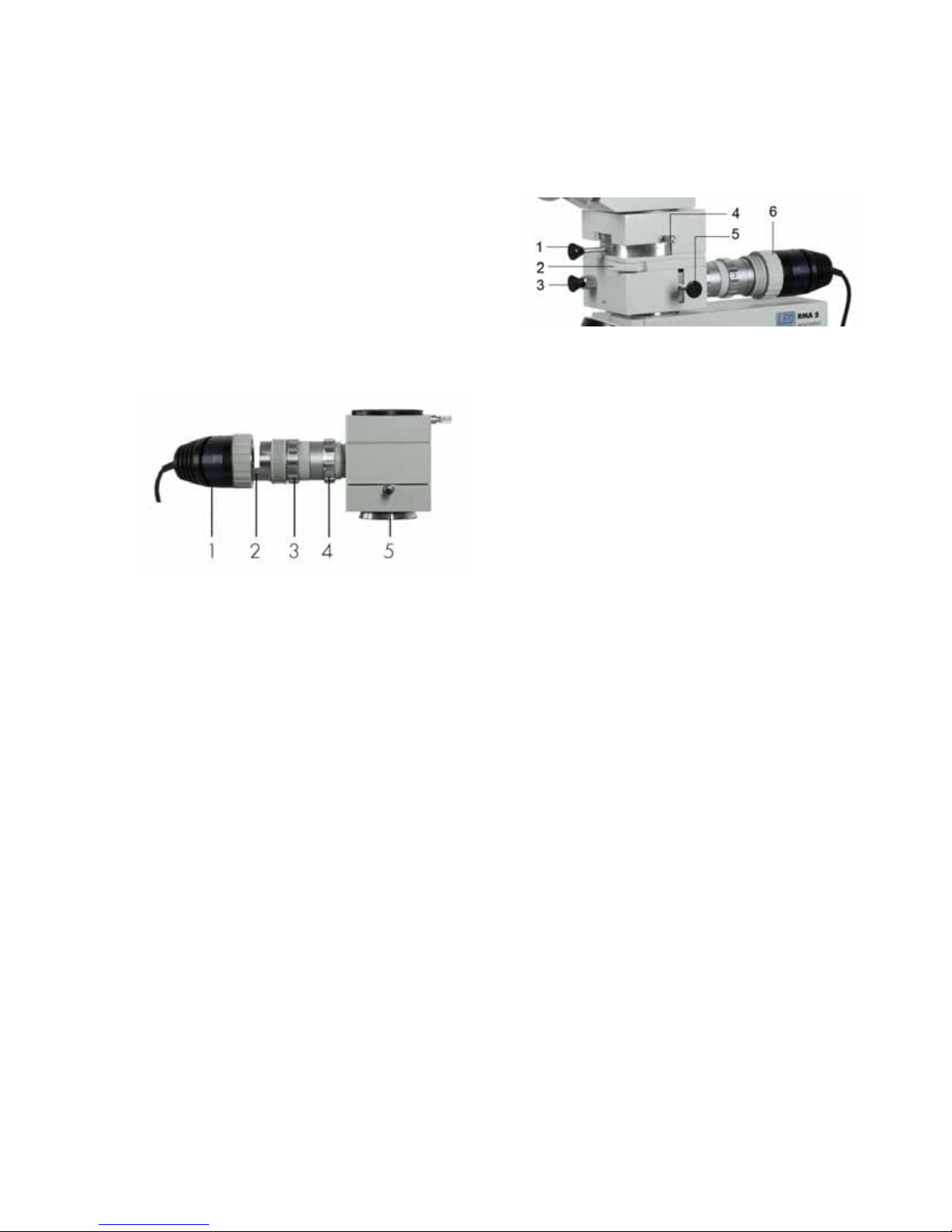
pic.3: overview – incident light tube
1 3W-LED illumination
2 Filter holder (opened)
3 Adjusting ring for the aperture stop
(aperture diaphragm)
4 Adjusting ring for the illuminated field
aperture (field diaphragm)
5 Intermediate tube (RMA 5 ∞)
2.4 Polarization units
2.4.1 Incident light polarization
pic.4: overview – incident light tube
1 analyzer slide
2 slide for compensator
3 slide for incident light
4 locking screw for analyzer
5 polarizer slide
6 incident light unit (pic. 3)
To active the incident light push the switch on the
left side of the stand and the slide for incident
light (3). The polarizer slide (5) is on the right
side of the tube. The 180° rotatable analyzer
slide (1) is can be clamped by the locking screw
(4). The incident light tube is the same as for the
RMA 5 ∞.(pic.3)

12
2.4.2 Transmitted light polarization
pic.5: overview – incident light tube
1 Analyzer slide
2 slide for compensator
3 locking screw for analyzer
The polarization microscope can only be used
with transmitted light. The polarizer slide is
placed in the condenser of the stage or can be
used as rotatable polarizer which is directly
mounted into the filter holder of the transmitted
light illumination of the microscope. The 180°
rotatable analyzer slide (1) is can be clamped
by the locking screw (3).
2.4.3 Compensator
pic.6: compensator slide λand λ/4
Compensator (λ; λ/4) filters can be used for
evaluation and measurement of optical path
differences and improvement or change of
image contrast. The compensator have their own
constant optical path difference (birefringence)
and are placed in a 45° angle between the two
crossed polarizers.

13
2.5. General Operating Instructions
2.5.1. The adjustment of the microscope in the
High positioning can be done with the drive
mechanism.
2.5.2. The illumination level can be changed
by changing the adjustment in front of the
microscope base or by using of different kind of
filters. With help of the aperture diaphragm it
is possible to change the contrast.
2.5.3. All tubes can be changed at the same
kind. The screw under the tube has to be
dissolve so that you can remove the tube. The
tube has to be set into the tube mount for
assembling the tube.
Don’t forget to clamp the screw again. If
necessary the tubes can be mount also by
rotating in 180°. It isn’t possible to use more
than one intermediate tube at the same time.
2.5.4. A change of the objectives is for all
existing objectives the same. The nosepiece has
a uniform, centred and adjusted W0,8” (RMS)
fine thread. Please handle all objectives with
care so that it can’t come off. Do not touch the
objective directly with your hands. A removed
objective should be placed again into the
protective packaging of the objective.
2.5.5. All fixed or adjustable eyepieces from
laboratory or technical microscopes can be used
in the microscope RMA 5.

14
3. Maintenance and Service
The Technical Microscope RMA 5 and its
supplemental equipment are service-free over a
long period of time, assuming normal use. In the
case of continual use (shift operation) and
especially in the case of unfavourable
environment conditions (dust, etc.), the unit
should be serviced when needed in the
following ways.
Before any servicing of the equipment, the
power supply should be disconnected.
Please be carefully with all optical parts. A
damage of these part will cause aberrations or
not sharpen images.
All loose parts, e.g. preparations, filter or so on
have to be removed from the microscope.
3.1. Changing the fuse
Warning: Do not adjust inadvertently the mark of
the main voltage!
3.1.1. The fuse of the microscope RMA 5 is
located in the base of the microscope. To
change the fuse you have to put the microscope
on the back and you have to open the base
plate carefully with a slotted bolt turner.
The defect fuse is to be replaced with a new
fuse (delay fuse 100mA for 115V to 230V).
After that the base plate can be closed and
saved with a screw again and the microscope
can be set up.
3.2. Care of components
3.2.1. The dioptre rings are unscrewed, those
threads easily greased and by repeated and
movement of the dioptre rings it is all greased
evenly. When mounting the rings, ensure that
their marks agree with the index lines on the
eyepiece connecting piece.
3.2.2. Eyepieces, tube and interchangeable
objectives should be cleaned regularly with a
soft hair brush. In addition these parts should be
removed from the equipment and all accessible
optical parts should be carefully cleaned. Each
attempt to disassemble the objective will cause a
complete adjustment error of the objective.
Optics and lenses can be cleaned by a
cleaning tissue for optics. Medical alcohol is
recommend as cleaner.
3.2.3. In case the microscope isn’t in use you
should cover the microscope with the delivered
protective cover.
3.2.4. We recommend to use antifriction
bearing grease of middle consistency for
lubricating the slide faces of the sliding stage.
Lightly lubricate both faces in regular time
intervals with this grease. Before doing this,
carefully remove the old grease with a grease
dissolver.
15
4. Supplementary
Equipment
4.1. Eyepieces
4.1.1. Fixed eyepieces are available for
different magnifications (first number) and with
different field of view numbers (second number).
With its assistance the total magnification can
be changed beyond the range of the
magnification changer, without the work
distance is affected. All eyepieces are
equipable with eyecups. All eyepieces GF – Pw
10x/20 and GF - P 16x/12,5 are usable as
eyeglass (spectacles) wearer eyepieces
(eyeglass symbol, ) .
4.1.2. Adjustable eyepieces will be offered for
simple measurements or for counting and can be
fitted with various reticles.
The fixed eyepiece will be removed and the
adjustable eyepiece will be inserted. By setting
the eye lens the adjustable eyepiece will be
focused on the reticle.
4.2. Tubes
4.2.1. The monocular straight tube is a tube,
which is used mainly as the second
perpendicular observation view in connection
with a binocular straight tube and a Phototube
pic.7: monocular straight tube
4.2.2. The polarized light able binocular
straight tube requires the use of two oculars of
the same enlargement [a fixed ocular for the left
adjustable tube pipe and an adjustable ocular]
for the right fixed tube pipe.
The sharpness adjustment can be done with the
adjustable eyepiece for the right side and with
the dioptre ring for the left side.
pic.8: binocular straight tube
The standard equipment of the binocular straight
tube is prepared for eyepieces with a plug-in
diameter of 30 mm. A special equipment is
prepared for eyepieces with a plug-in diameter
of 23,2 mm, or 23,2 mm eyepieces can also
be used in case with a special adapter.

16
4.3. Objectives
There are different kind of objectives, e.g. M-Plan
∞or achromatic objectives in different
magnifications (5x ; 10x ; 20x ; 50x)
pic.9: objectives
4.4. Colour filter
A blue matted glass with a diameter = 32 mm
can be done into a filter holder, so that the light
becomes daylight similar (if halogen light
illumination is in use). In order to change
generally the colour of the lighting, colour filters
are used, which are in a similar holder like the
blue matted glass.
5. Intermediate Tubes
5.1. Angled tube
The angled tube is used in connection with the
straight binocular tube. The tube is equipped with
a 30° angle and image erection (IE). It is
attached between the centre section of the
microscope and the straight binocular tube. (for
160mm Objectives)
pic.10: angled tube 30° with IE
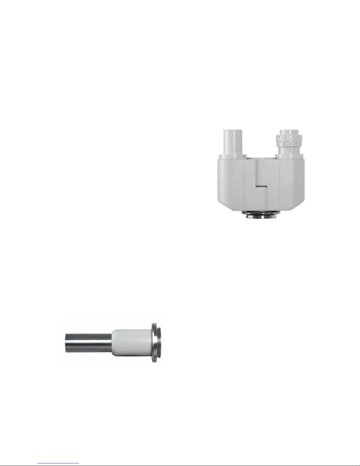
5.2. Photo-/TV tube
If binocular observation and photographic or
video-technical recording should take place
simultaneously, you can use the photo tube. The
tube is equipped with a 30° angle and image
erection (IE).The photo tube is set on the centre
part of the microscope and has connections for
the straight binocular tube and a photo or TV
adapter.
pic.11: photo tube 30° with IE
Beyond that a further Photo-/TV tube with a firm
division ratio of 80/20 are available, i.e. 80%
of the light are used for visual observation and
20% for the photographic reproduction or the
video image. (for 160mm Objectives)
17
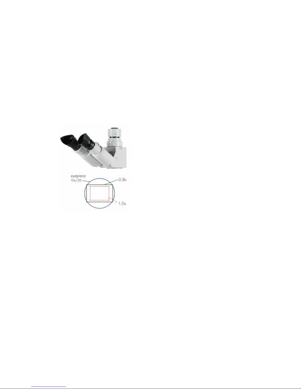
5.3 Wide Field Photo Tube for M-Plan
Objectives
The trinocular phototube 50/50 with image
erection is especially suited for visual
observation as well as photo and TV
documentation at the same time. For an optimal
view the visual optical path is equipped with a
30° angle.
The photo exit with a 0,8x magnification factor
means an according field of view adjustment for
a efficient pixel saturation and a wide
unvignetted image field.
pic.12: wide field photo tube
∞
1x/0,8x
6. Measuring instruments
6.1. Eyepiece measuring plate
The eyepiece measuring plates are provided
and a measuring scale is inserted into a
adjustable eyepiece.The eyepiece - cross-line
divides the field of view into 4 quadrants and
marks the field of views centre. To use the
eyepiece measuring plates the eyepiece - line
disk version is unscrewed, and the line plate is
inserted in such a way into these that the
engraving points downward to the object.
When connecting, the screen is again screwed
in.
6.2. Object measuring plate
The Object measuring plate serves for the
calibration of the measuring software for normal
and as well as for microscopic linear
measurements. The division is on the top side of
the plate. For calibrating, the division is turned to
the objective. For direct linear measurement of
even objects these are placed on the object
measuring plate with the division downward on
the object surface.
The object - surface plate 70/0.5 10/0.1
2/0.01 orders a calibration of 0.5mm and in
the centre a division length of 10 mm with a
calibration of 0.1 mm on a division length of
70mm. Moreover it orders a division of 2.0mm
with a calibration of 0.01mm additionally in the
centre of this division.
6.3. Measuring software
Objects can be captured with a video- or photo
camera which is mounted directly on a
microscope. These captured objects can be
stored in digital form. After a calibration of the
whole microscope system (with help of a
measuring plate) it is possible to measure this
objects.
Several measuring programs are available. For
the use of these programs it is necessary to
equip a computer with digital camera like a
digital USB camera or a digital D-SLR camera to
the microscope (over the Photo-/TV tube).
The measuring programs will be describe
separately in the manual of the manufacturer of
the software (the manual is not part of this
manual).

18
7. Documentation
7.1. Photography over Photo-/TV tube
If visual observation and photographic
photographs without changes are to be made,
then the use of the Photo-/TV tube offers itself. A
photo adjustment and the type of camera
appropriate T2 – adapter is needed. There are
different photo adjustments available: 1x ; 1,6x
and 3,2x.
It is better to insert into the adjustable eyepiece a
cross-line plate to see which part of the object
(picture) will be shown on the film and to
suppress the individual accommodation.
The Photo-/TV tube is mounted on the
intermediate tube and the photo adjustment on
the upper exit of the Photo-/TV tube itself. The
objective is removed from the camera and the
T2-adapter will be mounted there.
The photo adjustment cannot be adjusted,
because it is so balanced that after the normal
alignment of the microscope also the picture
appears sharp on the film level.
7.2 Digital photography
The connection of digital single lens reflex
cameras is done by a sensor fitted photo
adaptation and camera suited T2 adaptation
ring. Three different photo adaptation 1,0x;
1,6x; 3,2x are available.
For a maximum object field following optimal
combinations between sensor size an photo
adaptation are recommend:
Full frame 24,0mm x 36,0 mm →3,2x
APS-C 14,8mm x 22,2mm →1,6x
Four Thirds 13,5mm x 18,0mm →1,0x
pic.13: photo adaptations 3,2x; 1,6x; 1,0x

19
8. TV – Transfer
8.1. TV – Transfer over Photo-/TV tube
For the TV transfer is only a Photo-/TV tube and
a TV with camera and a monitor adjustment are
needed. For the right adaptation of the image
detail of the camera in comparison to the image
in the eyepiece there are four different TV-
adapter available with magnification factor
0,3x ; 0,4x ; 0,4xWF ; 0,63x ; 1x and 1,6x.
The Photo-/TV tube is set for adjustment on the
microscope centre section. At the upper exit of
the Photo-/TV tube will be mount the TV adapter
and above the TV adapter will be set a video
camera (in most cases the thread is c-mount)
All TV-adapter will be aligned factory-made at
the delivery. In normal case you don’t have to
change nothing. In case you don’t have a clear
picture you have to follow the instructions at
points 8.1.1 and 8.1.2.
8.1.1 The TV-adapter 1x comes in two parts
which will be clamped with two screws. The
lower part will be set directly on the Photo-/TV
tube, the upper part will be set on the T2-
adapter . Both parts will be add together and
will be adjust against each other at a good
aligned microscope with smallest magnification
factor until there is a clear and sharpen picture
on the monitor. Now you have to align the
camera itself (left and right side of a picture) and
the screws will be tighten.
pic.14: Tv – adaptation 0,3x … 1,6x
pic.15: phototube with Tv adaptation 0,63x
and camera
8.1.2 You have to do the same steps for the
TV-adapter 0,3x ; 0,4x ; 0,4x WF ; 0,63x and
1,6x (analogous in comparison to the TV-
adapter 1x)

20
9. Illumination
9.1. 3W – LED Transmitted light
For a research of transmitted objects it can be
helpful to observe the objects not only in incident
light illumination. The use of transmitted light
illumination is good to define structures much
more better.
pic.16: stage carrier with object guide and
condenser for transmitted light
Please note: The 3W-LED transmitted light can
be only used in combination with stage carrier
with object guide.
pic.17: optics for transmitted light (placed in the
stand)
Further it is necessary to use a condenser. The
condenser comes with a wide field lens and an
aperture stop.
9.2. Oblique incident light (dark field)
For a lot of objects dark field will most suited –
contours have a high contrast; finest structures,
reliefs, damages on surfaces are much more
better visible than with bright field illumination.
The equipment comes with an articulated arm
and a 3W-LED incident light illuminator,
focusable and a transformer for the 3W-LED
illumination, adjustable. This illumination is suited
for the objectives 5x; 10x; 20x.
pic.18: oblique incident light
Table of contents


