North American Tool 42801 User manual
NM00000OP 3/10
FACTORY SERVICED
8 Gallon Air Compressor
90-DAY LIMITED WARRANTY
FOR NON-COMMERCIAL USE
DO NOT RETURN THIS
PRODUCT TO THE RETAILER!
Replacement parts:
Replacement parts for this tool are
available at our authorized services
centers across the USA. For
servicing, contact us at the email
address or 800# below. Please be
prepared to provide the model#
located below the pump on the
product (directly above the UPC
code) and purchase date along
with your proof of purchase. Please
use the 4 digit number listed in the
parts breakdown diagram for all
parts orders (where applicable).
CALIFORNIA PROPOSITION 65
WARNING: You can create dust
when you cut, sand, drill or grind
materials such as wood,paint,
metal, concrete, cement, or other
masonry. This dust often
contains chemicals known to
cause cancer, birth defects, or
other reproductive harm. Wear
protective gear.
WARNING: This product or its
power cord may contain
chemicals, including lead,
known to the State of
California to cause cancer
and birth defects or other
reproductive harm. Wash
hands after handling.
Breathable Air Warning:
This compressor/pump is not
equipped and should not be
used “as is”to supply
breathing quality air. For any
application of air for human
consumption, the air
compressor/pump will need
to be fitted with suitable in-
line safety and alarm
equipment. This additional
equipment is necessary to
properly filter and purify the
air to meet minimal
specifications for Grade D
breathing as described in
Compressed Gas Association
Commodity Specification G
7.1 - 1966, OSHA 29 CFR
1910. 134, and/or Canadian
Standards Associations
(CSA).
Important Safety
Instructions
RISK OF EXPLOSION OR
FIRE:
It is normal for electrical
contacts within the motor and
pressure switch to spark.
Always operate the
compressor in a well
ventilated area free of
combustible materials such
as gasoline and solvent
vapors. If spraying flammable
materials, place the
compressor at least 20 feet
away from the spray area (an
additional length of hose may
be required).
If electrical sparks from the
compressor come in contact
with flammable vapors, they
may ignite, causing fire or
explosion. Covering any of
the compressor ventilation
openings will cause serious
overheating and possibly fire.
Model: 42801
STOP
feedback@natitools.com 89042801

2
Store flammable materials in a
secure location away from the
compressor. Never place
objects against or on top of the
compressor. Operate
compressor in an open area at
least 12 inches away from any
wall or obstruction that would
restrict the flow or fresh air to
the ventilation openings.
Operate compressor in a clean,
dry and well ventilated area. Do
not operate compressor indoors
in a confined area.
Unattended operation of this
compressor could result in
personal injury or property
damage. Always remain with
the compressor when it is
operating.
RISK OF BURSTING
Failure to properly drain
condensed water from the tank
can cause rust and thinning of
the tank. Drain tank daily or
after every use. If the tank
develops a leak, replace tank or
get a new air compressor.
Never drill into, weld or make
any modifications to the tank or
its attachments. Never make
any unauthorized modifications
to the unloader valve, safety
valve or any other components
which control tank pressure.The
tank is designed to withstand
specific operating pressures.
Never make any adjustments or
parts substitutions to alter the
factory set operating pressures.
Excessive vibration can weaken
the air tank and cause rupture or
explosion. Exceeding the
operating pressure of air tools
can cause them to explode. For
essential control of air pressure,
you must regulate the air using
an air regulator (or install one if
not provided) on the air outlet.
RISK OF BURNS
Touching exposed metal such as
the compressor head or outlet
tubes can result in serious burns.
Never touch any exposed metal
parts or compressor during or
immediately after operation. The
compressor will remain hot for
several minutes after use. Do not
touch areas around protective
shrouds or attempt maintenance
until the compressor has cooled
down completely.
RISK OF PROPERTY DAMAGE
WHEN TRANSPORTING
Oil can leak or spill and could
result in fire or breathing
hazards, serious injury , or death.
Oil leaks will damage carpet,
paint or other surfaces in
vehicles or trailers. Always place
compressor on a protective mat
when transporting to protect
against damage to vehicle from
leaks. Remove compressor from
vehicle immediately upon arrival.
AIR COMPRESSOR
SPECIFICATIONS AND
ELECTRICAL INFORMATION
Specifications:
Voltage……………………120V
Peak Horsepower………….1.5
Amperage………….……11.7A
RPM (no load speed) …..3400
Phase ……………….………...1
Hertz………………………60Hz
Max operating pressure 125psi
POWER SUPPLY
WARNING: YOUR
COMPRESSOR MUST BE
CONNECTED TO A 120V
BRANCH CIRCUIT WITH A
MINIMUM 15-AMP. FAILURE TO
CONNECT IN THIS WAY CAN
RESULT IN INJURY FROM
SHOCK OR FIRE
GROUNDING
Your compressor must be properly
grounded. Not all outlets are
properly grounded and if you are
unsure if your outlet is or not,
contact a qualified electrician.
WARNING: NOT PROPERLY
GROUNDING THIS
COMPRESSOR CAN CAUSE
ELECTRICAL SHOCK,
ESPECIALLY WHEN USED IN
DAMP LOCATIONS. IF THE
POWER CORD IS WORN OR
DAMACED IN ANY WAY, HAVE IT
REPLACED IMMEDIATELY TO
AVOID SHOCK OR FIRE.
feedback@natitools.com
3
If this compressor malfunctions
or breaks down, grounding
provides a path of least
resistance for the electric current
and reduces the risk of shock.
This cut-off is equipped with a
cord that has a grounding
conductor and plug. The plug
must be plugged into an
appropriate outlet that is properly
installed and grounded in
accordance with all local codes
and ordinances. TO
MAINTAIN PROPER
GROUNDING, DO NOT
REMOVE OR ALTER THE
GROUNDING PRONG IN ANY
MATTER.
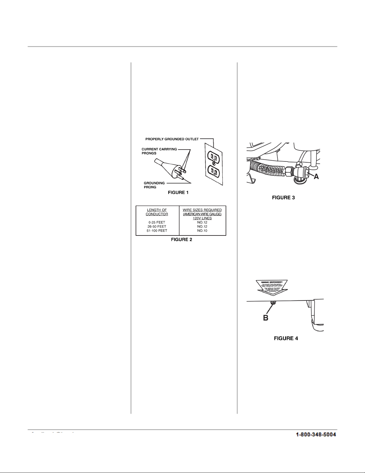
120V OPERATION
Your compressor is ready to run
using a 120V electrical supply
straight from the factory. This
machine is intended for use on a
circuit that has an outlet and a
plug which looks like the one
illustrated in Fig.1.
WARNING: Do not use a two-
prong adaptor, they are not in
accordance with local codes and
ordinances. Never use in
Canada.
EXTENSION CORDS
The use of any extension cord
will cause some loss of power. IT
IS RECOMMENDED TO USE A
LONGER AIR HOSE INSTEAD
OF AN EXTENSION CORD. If
you do not have a choice, use
the table in Fig.2 to determine
the minimum wire size (A.W.G. -
American Wire Gauge) extension
cord. Use only 3-wire extension
cords that have
3-prong grounding type plugs and
2-hole receptors.
For circuits that are further away
from the electrical circuit box, the
wire size must be increased
proportionately in order to deliver
ample voltage to the compressor
motor. Refer to Fig. 2 for wire
length and size.
CHECK VALVE (A) FIG.3
When the air compressor is
operating, the check valve is
‘open’, allowing compressed
air to enter the air tank. When
the air compressor reaches
‘cut-out’pressure, the check
valve ‘closes’, allowing
pressurized air to remain
inside the air tank.
AIR COMPRESSOR PUMP To
compress air, the piston moves up
and down in the cylinder. On the
down stroke, air is drawn in
through the intake valves. The
exhaust valves remain closed. On
the upstroke of the piston, air is
compressed. The intake valves
close and compressed air is
forced out through the exhaust
valves.
COOLING SYSTEM
This compressor contains an
advanced cooling fan. The cooling
fan is working when air is being
expelled.
DRAIN VALVE (A) FIG.4
The drain valve is located at
the bottom center of the air
tank and is used to drain
condensation from the tank at
the end of each use. Turn
valve clockwise to drain
condensation.
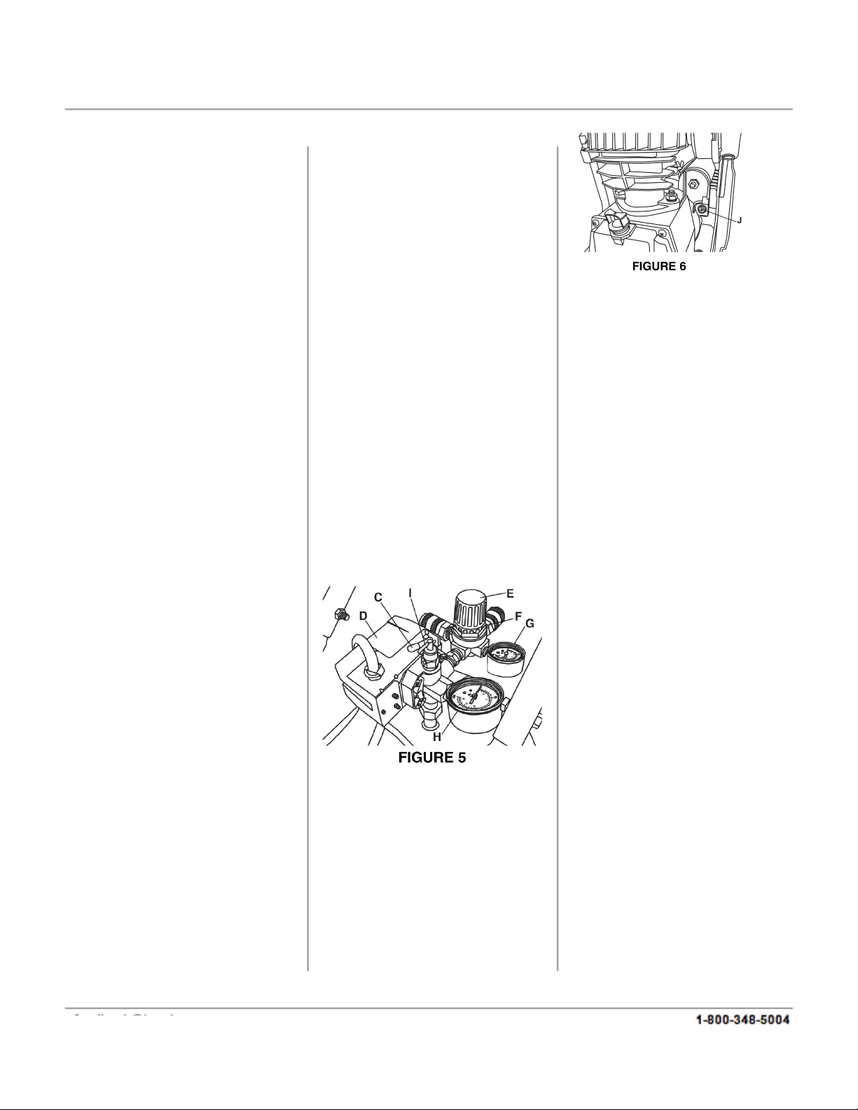
ON/AUTO-OFF SWITCH (C)
FIG.5
Turn this switch ON to provide
power to the automatic pressure
switch and OFF to remove power
at the end of each use.
feedback@natitools.com
4
PRESSURE SWITCH (D) FIG.5
The pressure switch automatically
starts the motor when the tank
pressure drops below the factory
set ‘cut-in’pressure. It also stops
the motor when the air tank
pressure reaches the factory set
‘cut-out’or maximum pressure.
REGULATOR (E & F) FIG.5
The air pressure coming from the
air tank is controlled by the
regulator (E). To unlock the
regulator, turn the regulator lock
rink (F) counterclockwise and then
turn the regulator clockwise to
increase pressure and
counterclockwise to decrease
pressure, tighten the regulator
lock rink to relock it into position.
To avoid minor readjustment after
making a change in the pressure
setting, always approach the
desired pressure from a lower
pressure. When reducing from a
higher to a lower setting, first
reduce the pressure less than that
desired, then bring it up to the
desired pressure. Depending on
the air requirements of each
particular accessory, the outlet
regulated air pressure may have
to be adjusted while operating the
accessory. This process may
require expelling air from the air
outlet, hose, tool, or accessory.
OUTLET PRESSURE GAUGE(G)
FIG.5
The outlet pressure gauge
indicates the air pressure
available at the outlet side of the
regulator. The pressure is
controlled by the regulator and is
always less than or equal to the
tank pressure.
TANK PRESSURE GAUGE (H)
FIG. 5. The tank
pressure gauge indicates the air
pressure in the tank.
SAFETY VALVE (I) FIG. 5. If the
pressure switch does not shut off
the air compressor at its cutout
pressure setting, this safety valve
will protect against high pressure
by popping out at its factory set
pressure (slightly higher than the
pressure switch cut-out setting).
WARNING!: If the safety valve
does not work properly, over
pressurization may occur,
causing air tank rupture or an
explosion. Daily pull the ring on
the safety valve to make sure
that the safety valve operates
freely. If the valve is stuck or
does not operate smoothly, it
must be replaced with the same
type of valve.
MOTOR THERMAL
OVERLOAD PROTECTOR
(RESET (J) FIG. 6). The electric
motor has an automatic thermal
overload protector. If the motor
overheats for any reason, the
thermal overload protector will
shut off the motor. The motor
must be allowed to cool before
restarting. Press the reset button
(J) after 15 minutes.
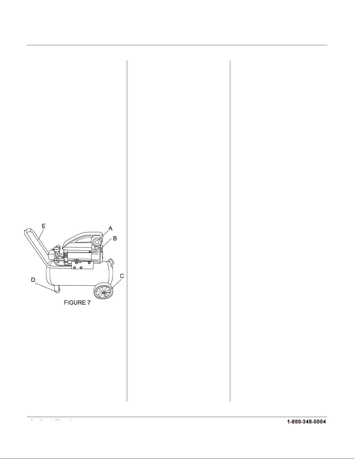
ASSEMBLY AND LOCATION
OF THE AIR COMPRESSOR
Your compressor requires some
assembly. Install intake filter (A)
Fig.7 to the cylinder cover.
Remove plastic cap and install
the oil breather cap (B) to the
crankcase cover. Install both
wheels (C) using the large hex.
bolts, spring washers and hex.
nuts supplied. Then install the 2
rubber feet (D) using the small
hex. bolts, washers, spring
washers and hex. nuts. Install
handle (E) and the storage
compartment (not shown) to the
tank using hex. bolts, washers,
spring washers and hex. nuts.
where applicable.
Operate the air compressor in a
cool, dry, clean and well
ventilated area. The air
compressor pump and case are
designed to allow for proper
cooling. Clean or blow off dust or
dirt that collects on the air
compressor. A clean air
feedback@natitools.com
5
compressor runs cooler and
provides longer service. The
ventilation openings on your air
compressor are necessary to
maintain proper operating
temperature. Do not place rags
or other containers on or near
these openings.
ADDITIONAL REGULATORS
AND CONTROLS
Since the air tank pressure is
usually greater than that which
is needed, a regulator is
employed to control the air
pressure ahead of any
individual driven device.
Separate air transformers which
combine the function of air
regulation, moisture and dirt
removal should be used where
applicable.
DOING THE FOLLOWING
BREAK-IN PROCEDURES.
SERIOUS DAMAGE MAY
RESULT IF THE FOLLOWING
BREAK-IN INSTRUCTIONS ARE
NOT CLOSELY FOLLOWED.
THIS PROCEDURE IS
REQUIRED BEFORE THE AIR
COMPRESSOR IS PUT INTO
SERVICE, OR AFTER
REPLACING THE CHECK
VALVE, AND WHEN THE
PISTON OR THE CYLINDER
SLEEVE IS REPLACED.
A. Set the pressure switch to the
OFF position.
B. Plug the power cord into the
correct branch circuit receptacle.
C. Turn the drain valve (B) Fig. 4
clockwise, opening it fully, to
prevent air pressure build-up in
the tank.
D. Move the pressure switch to
ON/AUTO. The compressor will
start.
E. Run the compressor for 15
minutes. Make sure the drain
valve is open and there is no tank
pressure build-up.
F. After 15 minutes, close the
drain valve by turning the knob.
The air receiver will fill to cut-out
pressure and the motor will stop.
The air compressor is now ready
for use.
OPERATING PROCEDURES
Preparation for use:
1. Before attaching air hose or
accessories, make sure the
OFF/AUTO is set to OFF and the
air regulator is closed.
2. Attach hose and accessories.
WARNING: Too much air
pressure causes a hazardous
risk of bursting. Check the
manufacturer's maximum
pressure rating for air tools
and accessories. The regulator
outlet pressure must never
exceed the maximum pressure
rating of the tool being used.
3. Turn the OFF/AUTO to ON
and allow tank pressure to
build. Motor will stop when
tank pressure reaches cut-out
pressure.
4. Open the regulator by
turning lock ring to unlock it
and then turning the regulator
clockwise. Adjust the regulator
to the correct pressure
setting.The compressor is
ready for use.
5. Always operate the air
compressor in well ventilated
areas; free of gasoline or other
solvent vapors. Do not operate
the compressor near a spray
gun operating area.
After Use:
6. Set the switch to OFF.
7. Lift then turn the regulator
button counterclockwise to set
the outlet pressure to zero and
finally push the button down
again to lock in place.
8. Remove the air tool or
accessory.
9. Pull ring on safety valve (I)
Fig. 5, allowing air to bleed
from the tank until tank
pressure is approximately
20psi. Release safety valve
ring.
BREAK-IN PROCEDURES
NOTE: MAKE SURE THAT
YOU HAVE FILLED THE
CRANKCASE WITH
COMPRESSOR OIL UP TO
THE CENTER DOT OF THE
OIL LEVEL AS DESCRIBED IN
THE MAINTENANCE
SECTION AND THAT ALL
ASSEMBLY INSTRUCTIONS
ABOVE HAVE BEEN
FOLLOWED BEFORE
feedback@natitools.com
6
10. Drain water from air tank.
Turn drain valve (B) Fig. 4,
clockwise to open.
WARNING!: WATER WILL
CONDENSE IN THE AIR
TANK. IF NOT DRAINED
WATER WILL CORRODE AND
WEAKEN THE AIR TANK
CAUSING A RISK OF AIR
TANK RUPTURE
NOTE: If drain valve is plugged,
pull ring on safety valve (I) Fig.
5, and hold until air pressure
has been released. The valve
can then be removed, cleaned,
and reinstalled.
ALL ADJUSTMENTS OR
REPAIRS MUST BE DONE
WITH THE COMPRESSOR
DISCONNECTED FROM THE
POWER SOURCE. FAILURE
TO COMPLY MAY RESULT IN
SERIOUS INJURY.
MAINTENANCE
Before doing any maintenance
or adjustments to your air
compressor, the following safety
precautions should be taken:
- Disconnect electrical power.
-Drain air tank of pressure.
Daily or before each use
1. With the compressor on a
relatively level surface, check oil
level. Oil level should be
centered with the red dot.
2. Drain condensation from
tank.
3. Check for any unusual noise
or vibration.
4. Be sure all nuts and bolts are
tight.
Monthly
1. Inspect air system for leaks by
applying soapy water to all joints.
Tighten those joints if leakage is
observed.
250 hours of use or six months
(which ever comes first)
1. Change compressor oil. See
following instructions.
2. Replace oil more often if
compressor is used near paint
spraying operations or in dusty
environments.
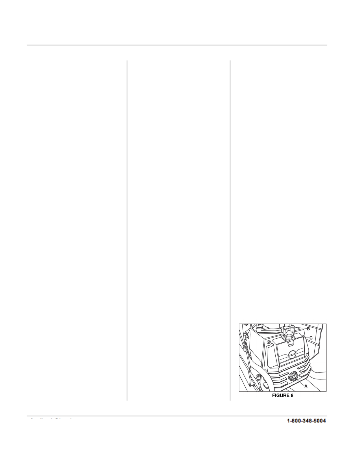
CHANGING OIL
To change oil, oil must be drained
from the crankcase by removing
oil sight glass (A) Fig.8. Drain oil
into a small receptacle and
replace oil sight glass. To fill the
crank case with oil, first unscrew
and remove oil breather cap (B),
pour approximately 300ml of air
compressor oil (SAE 10W30 or
SAE 10W20 non detergent oil)
into crankcase oil opening (C)
until the oil level reaches the
center red dot on the oil sight
glass. Retighten oil breather cap
(B).
KEEP TOOL CLEAN
Periodically blow out all air
passages with dry compressed
air. Clean all plastic parts with a
soft damp cloth. NEVER use
solvents to clean plastic parts.
They could possibly dissolve or
otherwise damage the material.
CAUTION: Wear safety glasses
while using compressed air.
FAILURE TO START
If your compressor fails to start,
check to make sure the plug is
properly connected to the outlet.
Also, check for blown fuses or open
circuit breakers in the line. If using an
extension cord, try using a longer air
hose instead and try restarting the
compressor.
STORAGE
1. Set the OFF/AUTO button to OFF
2.Lift and turn the regulator
counterclockwise to set the outlet
pressure to zero.
3. Remove the air tool or accessory .
4. Pull ring on safety valve (I) Fig. 5,
allowing air to bleed from the tank,
until tank pressure is approximately
20psi. Release safety valve ring.
5. Drain water from air tank. Turn
drain valve (B) Fig. 4, clockwise, to
open.
NOTE: If drain valve is plugged, pull
ring on safety valve (I) Fig. 5, and
hold until air pressure has been
released. The valve can then be
removed, cleaned, and reinstalled
6. After the water has been
completely drained, turn drain valve
to close. The air compressor can now
be stored.
7. Protect the electrical cord and air
hose from damage by winding them
loosely around the air compressor.
8. Store the air compressor in a clean
and dry location.
feedback@natitools.com

7
-Replace oil with SAE 10W30 or
SAE 10W20 non detergent oil
(300ML)
-Drain crankcase and fill to
proper level
-Air pressure regulated too high -
Replace filter
-Improper oil viscosity
-Too much oil in crankcase
-Compressor overheated
-Restricted air filter
Oil discharge in air
-Check for proper adjustment
and if problem persists, replace
pressure switch
-Defective pressure switch or improper
adjustment
Safety valve releasing
-Check valve manually by pulling
upwards on ring. If condition
persists replace valve
-Clean or replace as necessary -
Replace check valve
-Air leak in safety valve
-Restricted air filter
-Defective check valve
Low pressure
-Check voltage, eliminate
extension cord or reset
-Check wiring connections
-Press the reset button or wait for
automatic reset (15 minutes)
-Fuse blown or circuit breaker tripped -
Loose electrical connections -
Overheated motor
Not starting
Corrective ActionPossible Cause(s)Symptom
feedback@natitools.com

8
North American Tool (NAT) Industries makes every effort to ensure that this product meets high
quality and durability standards. NAT warrants to the original retail consumer a 90-Day limited
warranty from the date the product was purchased at retail and each product is free from defects in
materials. Warranty does not apply to defects due directly or indirectly to misuse, abuse, negligence or
accidents, repairs or alterations, or a lack of maintenance. NAT shall in no event be liable for death,
injuries to persons or property, or for incidental, special or consequential damages arising from the
use of our products. To receive service under warranty, the original manufacturer part must be
returned for examination by an authorized service center. Shipping and handling charges may apply. If
a defect is found, NAT will either repair or replace the product at its discretion.
feedback@natitools.com
feedback@natitools.com 89042801

feedback@natitools.com
Table of contents
Other North American Tool Air Compressor manuals


