MILE HIGH WINGS XACT User manual

Xact
Composite Aerobatic ARF
INSTRUCTIONAL MANUAL
Wingspan: 54.7in (1390 mm)
Length: 51in (1295 mm)
Wing Area: 550 sq.in (35.5 dm2)
Flying Weight: 4.6 lb (2.1 kg)
Wing Loading: 19.5 oz/sq.ft (60 g/dm2)
Engine Req. : .40-.61 2s/.50-.70 4s or electric
Mile High Wings
Boulder, Colorado, USA
www.milehighwings.com

2
TABLE OF CONTENTS
INTRODUCTION........................................2
SAFETY........................................................2
Radio..............................................................3
Engine Recommendations .............................3
ITEMS REQUIRED....................................3
Hardware and Accessories.............................3
Adhesives and Building Supplies ..................3
Optional Supplies and Tools..........................3
KIT CONTENTS.........................................4
GLUING INSTRUCTIONS........................4
ASSEMBLING THE PLANE.....................4
1. Installing Control Horns
on Stabilizer and Rudder............................4
2. Installing Horizontal Stabilizer..................4
3. Installing Rudder and Tail Wheel..............4
4. Mounting Rudder and Elevator
Servos.........................................................5
5. Adjusting Elevator and Rudder
Control Rods..............................................5
6. Mounting Aileron Servos and
Control Horns.............................................5
7. Mounting Engine and Throttle Servo ........6
8. Installing Fuel Tank...................................6
9. Installing Main Gear..................................7
10. Mounting Receiver and Battery...............7
11. Attaching Wings ......................................7
12. Setting Control Throws............................7
INTRODUCTION
Thank you for purchasing this plane.
Xact is not recommended as the first plane as
it does not have excessive stability, typical for
a trainer. Instead, Xact offers impressive
aerobatic performance due to its light weight
and low inertia. Its structural design is based
on the best F3A pattern ships, but its smaller
size allows for the use of inexpensive engines
and standard servos. Despite the light weight
of the plane, all the high stressed areas, like
wing and gear mounts, were designed with
large safety factors—they will withstand
excessive loads without damage. High degree
of pre-fabrication reduces your building time.
We hope you will enjoy flying this plane!
SAFETY
1. If your Xact is not assembled and operated
correctly, it could possibly cause injury to
yourself or spectators and damage to
property.
2. You must use R/C radio on a legal
frequency and in good operational
condition. It is a good idea to send your
radio for service in one of the certified
service centers (e.g., Futaba is serviced by
Great Planes / Tower Hobbies and their
prices are very reasonable; Hitec has very
long warranty and often fixes everything
free of charge).
3. You must correctly install all R/C and
other components, so that the model
performs flawlessly on the ground and in
the air.
4. You must check the operation of the mo-
del before every flight to insure that all
equipment is operating and that the model
is structurally sound. Be sure to check
clevises and other connectors often and
replace them at first signs of wear.

3
5. If you are not an experienced R/C pilot,
you should fly the model only with the
help of an experienced R/C pilot.
6. WARNING:Xact is made of fiberglass,
which fibers may cause eye, skin and
respiratory tract irritation. Never blow into
a part to remove fiberglass dust, as dust
will get into your eyes. Always wear
safety goggles, a particle mask, and rubber
gloves when grinding, drilling, sanding
and gluing fiberglass parts. Vacuum the
parts and work area thoroughly after work.
To fly this model at AMA (Academy of
Model Aeronautics) sanctioned clubs you
have to join AMA. AMA has over 2,500
chartered clubs across the country. You can
find more information at AMA Web site:
www.modelaircraft.org
No liability or responsibility is assumed by
Mile High Wings for any injury or damage
incurred as a result of using this product.
Radio
If you use a 4-channel radio, you will have to
utilize Y-harness to drive aileron servos. A
6+-channel computer radio is recommended.
Standard size servos can be used for the
rudder and the elevator, though mini servos
may be used to save weight. For ailerons, we
recommend mini servos, like Hitec 225, as
they are easier to install in the wings.
Engine Recommendations
A light .40 to .50 size two-stroke engine with
an appropriate propeller. Electric motor of
about 450W power (to achieve 100W/lb
power loading) can be used.
ITEMS REQUIRED
Hardware and Accessories
Virtually no extra hardware is needed, as
everything is provided in this kit. You will
only need engine mounting screws and blind
nuts as well as servo mounting hardware,
which comes with the servos.
Adhesives and Building Supplies
You will need small amount of slow curing
epoxy, which is stronger than 5- or 30-munute
flavors, as well as some high strength filler,
e.g. Aerosil Microfiber (Aerospace Composite
Products part EF-01). Microsphere is not
recommended as, while saving weight, it
greatly reduces the strength of the glue joint.
You may also need CA glue for servo mounts.
Optional Supplies and Tools
We recommend installing fuel filters and
fueling valve, e.g. Great Planes Easy Fueler.
The regular set of modeling tools should be
sufficient for assembling the plane. Dremel-
type rotor tool is convenient to cut holes in the
cowl. Fine sand paper is needed for surface
preparation before gluing the stabilizer and
servo mounts.

4
KIT CONTENTS
1. Wings with ailerons
2. Fuselage and cowl
3. Stabilizer with elevator
4. Rudder
5. Wing tube
6. Landing gear
7. 2.5” Lightweight wheels, 2
8. Wheel mounting hardware, 2 sets
9. Tail wheel assembly
10. Canopy
11. 2” Spinner
12. 8oz Fuel tank
13. Control rods, 2
14. Control horns small (for tail feather), 2
15. Control horns large (for ailerons), 2
16. Clevises, 4
17. Du-Bro E/Z Links, 4
18. Plastic wing-nuts
19. M2×16mm screws, 4
20. Fuselage servo panel
GLUING INSTRUCTIONS
Unlike typical built-up balsa planes, this ARF
requires very little gluing. You will only have
to glue:
-horizontal stabilizer to the fuselage
-rudder hinges
-servo mounts
We recommend the use of slow curing epoxy
mixed with Aerosil Microfiber (e.g.,
Aerospace Composite Products part EF-01).
When gluing balsa to the fiberglass, sand
fiberglass surface lightly with 120 grit or finer
sandpaper, then apply very little clear epoxy
to the balsa surface, mix the remaining epoxy
with Aerosil to the thickness of sour cream
and apply a thin layer of the mix to any of the
two surfaces. Press the parts together leaving
1/16” (1.5mm) fillet around the joint.
ASSEMBLING THE PLANE
1. Installing Control Horns on Stabilizer
and Rudder
It is easier to install control horns before
gluing the elevator and the rudder to the
fuselage. The elevator control horn is located
at the bottom surface of the starboard (right)
half of the elevator. Position it as close to the
centerline as possible with all the base of the
horn touching the elevator. Temporarily
install the rudder and position the control horn
at the same level as the control rod exit hole in
the fuselage. Make sure that the screws of the
rudder horn do not interfere with the hole for
the tail wheel bracket. Always make sure that
the clevis attachment holes in the control horn
are located exactly above the hinge centerline.
2. Installing Horizontal Stabilizer
Temporarily install the wings.
Insert the horizontal stabilizer into the
fuselage slot and align it by measuring the
distances from the wing trailing edges to the
tips of the stabilizer. Mark the outline of the
fuselage on the stabilizer and put electric tape
on the top and bottom surfaces of the
stabilizer 1/32” (1mm) outside of the
markings.
Figure 1.
5
Sand the paint off the thin strip of the
stabilizer, which will contact the fuselage. Be
careful not to damage the fiberglass, just
remove the paint. Apply small amount of
Aerosil/epoxy mix to the fuselage and/or to
the stabilizer; insert the stabilizer into the
fuselage slot aligning it to the electric tape;
remove excessive mix from the outside of the
joints to form 1/32” (1mm) fillet.
3. Installing Rudder and Tail Wheel
Apply generous amounts of Aerosil/epoxy
mix into the hinge slots in the fuselage as well
as a little of the mix on the hinges. First, glue
the plastic bearing of the tail wheel bracket
into the slot in the fuselage and screw the
aluminum plate to the bottom of the fuselage
to hold the bracket in place. Apply some
Aerosil/epoxy mix into the bracket hole in the
rudder and slide the rudder in place.
Figure 2.
4. Mounting Rudder and Elevator Servos
Make cut-outs in the servo mounting panel for
the servos you are using. Glue the panel to the
fuselage in front of the rear wing threaded
rods (make sure there is enough clearance for
the wing nuts):
Figure 3.
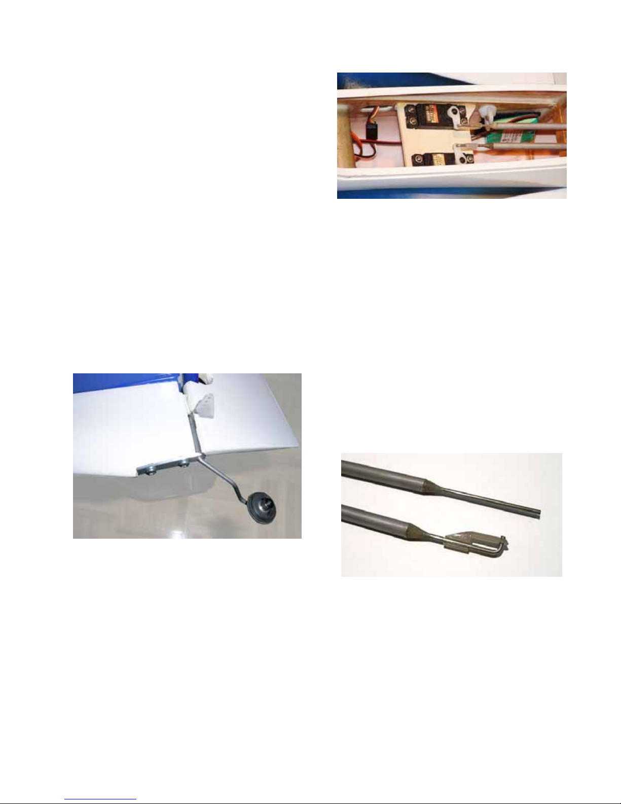
5. Adjusting Elevator and Rudder Control
Rods
Install the control rods in the fuselage with the
threaded ends backward. Thread clevises onto
the control rods and then mount them on the
rudder and elevator control horns. With the
fuselage servos in place, mark the location of
the servo arm holes on the control rod wires.
Unscrew the clevises and remove the control
rods from the fuselage. Bend the control rod
wire by applying the force to the wire and not
to the aluminum tubing. Cut the wire 3/8”
(10mm) off the bend and snap Du-Bro E/Z
Link onto it:
Figure 4.
6. Mounting Aileron Servos and Control
Horns
Cut pieces of scrap balsa or bass wood to size,
screw the aileron servo to them the usual way
and glue balsa to the wing. If you want to be
able to easily remove the servo from the wing,
you can make a simple servo mount as shown
below:

6
Figure 5.
Once the servo is secured in the wing, cut a
slot for the servo arm in the servo bay lid then
fix it in place with the scotch. Make control
rods from the piano wire using the supplied
clevises and E/Z Link-s.
Figure 6.
7. Mounting Engine and Throttle Servo
The plywood motor mounts are spaced for
O.S. 46LA engine. For larger engines, you
may need to remove some material using a
rotary tool. Position the engine so that the
prop drive washer with the spinner back plate
makes at least 1/16” (1.5mm) clearance with
the fuselage. Drill the holes for the engine
mounting bolts and install suitable T-nuts on
the rear surface of the motor mount.
Figure 7.
You may have to remove the carburetor from
the engine while you are positioning it, and,
after the engine position is determined, you
may need to remove some material from the
nose of the fuselage for the carburetor to fit.
The throttle servo can be mounted behind the
engine (a mini-size servo can be installed
sideways, as moving the throttle arm does not
require much force):
Figure 8.
For convenience, you may install Great Planes
Easy Fueler (part GPMQ4160, not included)
on an aluminum bracket glued to the firewall.

7
Using a rotary tool cut ventilation and other
necessary holes in the cowl.
Figure 9.
8. Installing Fuel Tank
Assemble and install the fuel tank behind the
firewall, wedging it inside the fuselage with
pieces of foam and/or bubble wrap.
9. Installing Main Gear
Using M4 screws, mount the wheels on the
main gear: put a washer, the wheel, then
another washer followed by a plain M4 nut,
then the gear, and the stop nut, as shown in
Figure 10:
Figure 10.
10. Mounting Receiver and Battery
Mount the receiver and the battery using
Velcro with sticky backing. Position them so
that the C.G. is located exactly at the axis of
the wing tube.
11. Attaching Wings
Insert the wing tube into the fuselage and
carefully slide the wings on the tube. Screw
four plastic wing nuts onto the threaded wing
inserts. Wing nuts should turn rather tight,
which is normal.
12. Setting Control Throws
Xact is a very light plane with all the heavy
components (engine, battery, etc.) are located
near its center of gravity. Because of this, it
has small moments of inertia and requires
unusually little control surface deflections.
Please set the following maximum control
throws, at least for the first flights:
ELEVATOR ± 1” (± 25mm)
RUDDER ± 1.25” (± 32mm)
AILERON ± 0.5” (± 12mm)
Even though the above control throws may
seem small, you will discover that they are
sufficient for all the maneuvers.
Table of contents
Popular Toy manuals by other brands

Staufenbiel
Staufenbiel Aquila instruction manual

Chipolino
Chipolino JUMBO owner's manual

Microaces
Microaces North American Mustang P-51D Assembly instructions

Hartland Locomotive Works
Hartland Locomotive Works Emma Nevada Operation manual

Jamara
Jamara Mercedes-Benz Arocs instructions

LEGO
LEGO SPEED CHAMPIONS 75875 Building instructions

Fisher-Price
Fisher-Price BUBBLE MOWER H8910 manual

RTS
RTS 7C7 Assembly instructions

Fisher-Price
Fisher-Price K6779 instruction sheet

Hasbro
Hasbro Fur Real Friends Daisy Plays-with-me kitty care guide

Hobby Lobby International
Hobby Lobby International TEL1600 manual

POLA G
POLA G Residential Building with Pergola 331084 Assembly instructions


