Hobby Lobby International TEL1600 User manual

SENIOR TELEMASTER KIT
TEL1600
MADE IN THE USA
Hobby Lobby International
5614 Franklin Pike Circle
Brentwood TN 37027 USA
Phone 866-512-1444
TEL1600 -REV 1.13


Terminology used in this manual.
With the precision of laser cut parts and notch and tab construction, the assembly and gluing sequence becomes very im-
portant. If components are glued in place to soon, they will not allow enough movement to install other components. When
instructed to install a part, do only that. You will be instructed to glue it when it is no longer required to be moveable.
Test Fit:
Test t and install but do not glue.
Install and glue:
Permanently install the part.
Locate and prepare:
Find the parts requested, you can locate them faster using the parts locator pages at the back of this manual. The parts locator
will direct you to the correct sheet number as well as describe the part for easier identication. Most of the parts are sup-
plied still in the sheet. These sheets are called the carrier sheet and the parts are held in the carrier sheet by small breaks in
the cutting line. These are called retainer breaks and in most cases the parts can be extricated by simply exing the carrier
sheet and the retainer breaks will release the parts. In harder materials it may be necessary to use your hobby knife to sever
the retainer breaks to remove the parts. After removing the parts, a small nub may remain where the retainer break was, this
must be removed with a light swipe of sandpaper so it will not interfere with the parts t.
Adhesives:
There are four primary types of adhesives recommended for constructing your model. They are CyanoAcrilate (referred to
as CA) in all viscosities, Aliphatic Resin Glue (carpenters glue), Polyurethane glue referred to as PU and Epoxy. CA is the
primary adhesive to use however there are times when it is not the best choice.
They are:
1. When you need more time to carefully position a part than a fast setting adhesive will allow.
2. When attaching plastic such as a windshield (Use Pacer formula 560 here).
3. When gluing laser cut aircraft grade plywood’s. The microwave set adhesives used in aircraft grade plywood does not
ablate well under a laser beam. As a result it burns the wood bers near by leaving a charred edge. Fast setting CA ad-
hesives do not allow time for the adhesive to penetrate this layer of char and bond to the wood ber underneath. Use a
slower setting adhesive such as Aliphatic Resin for maximum strength use Epoxy on aircraft grade ply parts. Lite Ply’s do
not use this type of adhesive and do not suffer from this problem.
To apply thin CA we recommend the Dave Brown pipets available from Hobby Lobby. Be sure to stretch the end (pull it
with a pair of pliers) to a thin applicator tip, as they are not supplied in this conguration.
1
Assembling the registration pins.
We will be using two types of pins; registration pins and push pins.
Registration pins are assembled from two ber blocks and two
specially prepared 2-1/2” nails. Push pins will be used to tempo-
rarily secure parts to the building board.
Locate the two pinning blocks supplied. Note that they have a
counter sink on one side. This is the side that the nail must be
inserted from. Place the block on a piece of scrap wood to prevent
the ber block from tearing out when the nail is driven through.
Now hammer the nail through just far enough to exit the block.
Next place the block up against the side of the bench or other
heavy object and nish installing the nail. When done, the nail
head should be in the recess so the block can sit at on the bench.
Repeat this process with the second pinning block assembly.

c 1
WING ASSEMBLY
2
c 3
c 2
During the wing assembly you will be making several subassemblies. In some cases you will be making
a left and right-handed assembly. It is best to make both assemblies at the same time in a mirror image of
each other to minimize the possibility of making two assemblies of the same hand. In the case of the rib
doublers, it is important that these be installed on the correct side of the rib. To help clarify this we will
refer to these as the Root Side and Tip Side of the part. The Root Side being the side that faces the direction
of the wing root and the Tip Side being the side that faces the wing tip. Compare each assembly to the plans
each time as they may vary. If installed on the wrong side of the rib they will not function properly.
Cut the wing plans between the left and right
panel and lay one of the plans on the work-
bench. Cover the plans with waxed paper. The
root rib assembly, W1 is composed of two
1/8” ply ribs (W1-IN and W1-OUT) that must
be assembled before installing into the wing.
This is an example of a left and right-handed
assembly. W1-IN should be facing into the
wing (Tip Side) and W1-OUT should be fac-
ing toward the fuselage (Root Side) when the
assembly is installed into the wing. Locate
W1-IN and W1-OUT and use the registra-
tion pins in the holes provided at the front and
back of the ribs to assemble them. Use plenty
of pressure to hold the assembly perfectly at
until the glue has cured. Assemble bothW1
assemblies at the same time.
The W1/W1-A assembly in the background is for the left wing. The
right wing W1 assembly is being prepared in the foreground with
W1 on the bottom and W1-A about to be glued to it on the registra-
tion pins. This pin positioning system will be used thoughout the
build.
Use a 3/16” dowel as a temporary alignment
tool to align W1-C with the 3/16” hole at the
aft end of the W1 assembly and the glue W1-C
in place. W1-C should be on the Tip Side of
the W1 assembly.
W1-C will serve as a guide for the anti pivot pin when installed.
Here it is being positioned by the temporary use of a 3/16” dowel.
Take care not to glue the dowel into the assembly.
Using the registration pins in the holes pro-
vided, glue W1-A to the W1 assembly on the
Tip Side.

3
c 13
c 12
c 11
c 10
c 9
c 8
c 7
c 6
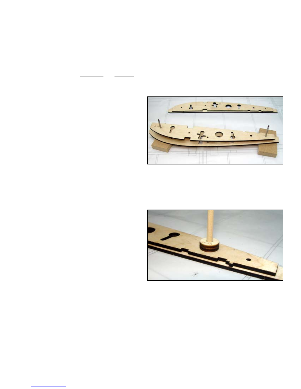
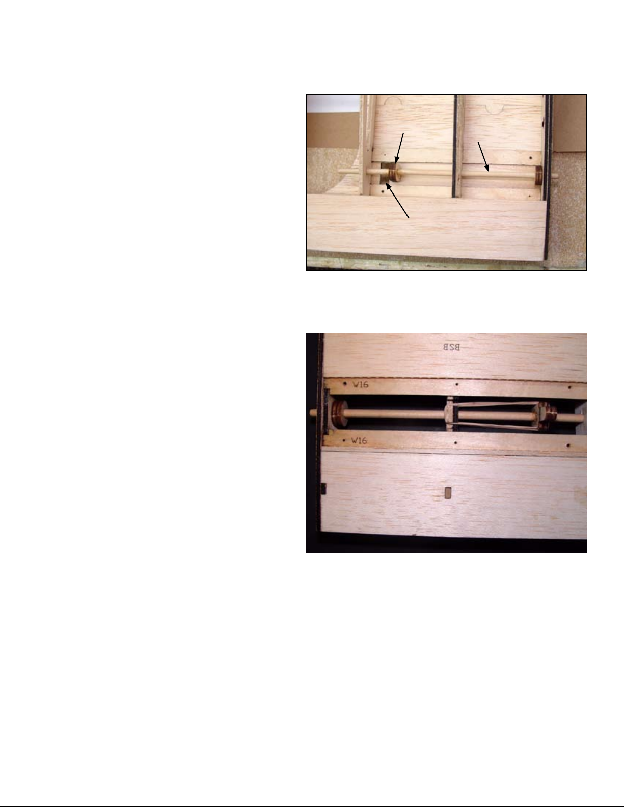
c 4The dihedral angle will be set by W1-B so it
is important that W1-B be accurately tted in
position, Glue W1-B to the W1 assembly en-
gaging the notch in W1-A. W1-B must be per-
fectly at against the W1 assembly. Use the
building square to insure that W1-B is at 90°
to the W1 assembly.
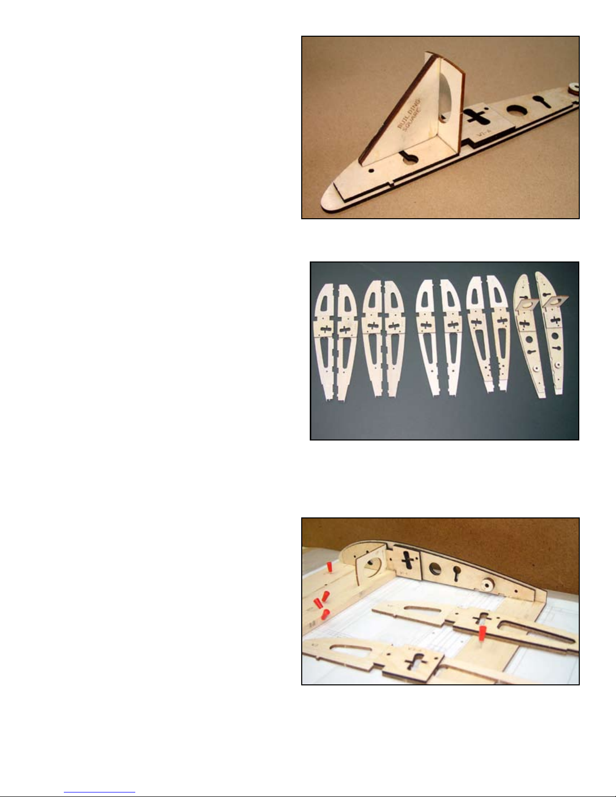
c 5Again, using the registration pins in the holes
provided, glue W2-A to W2. Note that W2-A
should be on the Tip Side of W2.
Glue W3-A to the Tip Side of W3.
Glue W4-A to the Root Side of W4.
Glue W5-A to the Tip Side of W5.
Carefully align the leading edge plate (LEP-
A) with the plans and pin in place. You may
notice a discrepancy between the parts and
the plans as far as position is concerned. This
is normal as the paper the plans are printed
on can change size with changes in tempera-
ture and humidity. Align the slot in TEP with
the W2 on the plans and use the plans only to
align the parts. The parts are correct.
W1-B will determine the correct dihedral angle for your wing so it
must be assembled accurately. Make sure it is fully engaged in the
tab of W1-A and at against the W1 assembly.
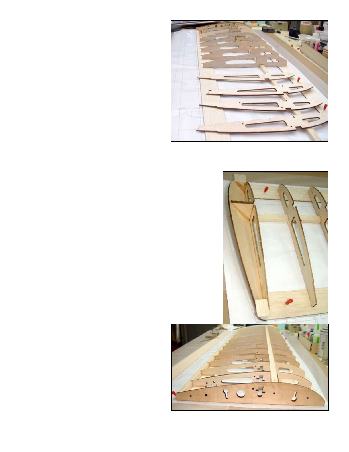
The rib subassemblies should look like this. It is best to assembly
them all at the same time to avoid errors. When installing them into
the wing, observe the correct direction they face, Root Side or Tip
Side as they will vary.
Temporarily place ribs W2 and W13 in there
respective notches in LEP, place a 3/8” x 1/2”
X 48” balsa spar in the bottom notches in each
rib to align it and then pin it at W2 and W13.
Place (TEP) into position with the notches for
Ribs W2 and W13 fully engaged. Make sure
ribs W2 and W13 are perfectly parallel with
the ribs on the plans and then pin TEP and
the bottom spar in place then remove W2 and
W13.
W1W5 W4 W3 W2
Carefully align the bottom sheeting part A
(BSA) to LEP and glue it to LEP.
Use Epoxy to glue the W1 assembly to the
wing assembly, LEP, TEP, BSA and the bot-
tom spar. Make sure the bottom spar is fully
engaged in the notch provided in the W1 as-
sembly and that W1-B is glued to the bottom
spar. W1-B will set the correct dihedral so it
must be at against BSA when installed.
LEP and TEP have been positioned. BSA has been installed and
now the W1 assembly is being Epoxyed to the wing assembly.

4
c 17
c 16
c 15
c 14 Loose t all ribs into there appropriate notches
in LEP, then use thin CA to glue them in and
use the Building Square to insure that each rib
is at 90° to the bench. Assure that all ribs are
bottomed in there respective notches before
applying glue. Glue them at LEP, the bottom
spar and TEP. Ribs W2 and W3 will also be
glued to BSA. NOTE: Ribs W2 through W6
must be in their correct locations or you will
not be able to insert the wing bar later. They
look very similar however the buttery open-
ing is cut to accommodate the dihedral angle
and will not line up if out of sequence.
Trim the bottom spar ush with the outside
of W15.
Plane or sand a slight bevel on the bottom of the wing tip (WT)
to increase glue land. Use the 45° gusset (WTG) to get the correct
angle on it and glue it at the leading and trailing edge as well as
the gusset. Align the gusset on center with the spar. Glue in a 1”
piece of 1” triangle stock at the leading edge and a 1” piece of
¾” triangle stock at the trailing edge. Cut and glue pieces of 3/8”
triangle stoct to W14 and WT between the leading edge and the
gusset and between the gusset and the trailing edge. Use a razor
plane to plane the leading edge and trailing edge triangle stock
ller pieces to contour with W15 and WT. Use a straight edge
across the top of W14 and W15 to help align the top of WT.
Place the top spar in position in the notches
provided and mark the location of the W1
assembly. Trim the spar off at this line then
place the spar in position and use aliphatic
resin to glue in the top spar. Weight it to as-
sure it remains bottomed in the rib notches
until cured.
RIGHT: the wing tip (WT) has been in-
stalled with WTG and the triangle stock
for and aft, all that remains is to place the
1/4” triangle stock at the bottom.
Glue on the ½” x ½” x 48” trailing edge, make
sure it is also glued to each rib.
c 18
Top spar and trailing edge installed, next will be the trailing edge
top sheeting being prepared at the left.
Rib installation is underway, make sure each rib is in the correct
location and use the building square to insure all ribs are perpen-
dicular to the bench.

5
c 23
c 22
c 21
c 19 Use a razor plane to shape the trailing edge of
the ½” square into contour with the ribs. Use
a short straight edge to guide material remov-
al. Plane the tip to contour with the ribs and
trailing edge as well. The trailing edge sheet
will extend out to the wing tip. When shaping
the tip, use a straight edge laid on top of W14
and W15 to determine when WT is correctly
shaped.
Planing the trailing edge to contour with the ribs. here one of the
pinning blocks serves as a straight edge to check material removal.
c 20 Install and glue 3/32” sheer webs to the front
of the spars, make sure that the sheer webs
are ush with the top of the ribs. Between W3
and W4 use SW-W4, this sheer web must also
be ush with the tops of the ribs. This will
provide a ledge for installing the leading edge
sheeting later.
Install and glue the ½” x ¾” x 48” leading
edge to LEP and each rib.
Cut two 12-1/2” pieces of 1/8” x ¼” bass-
wood these will be the Wing Bar Guide Rails.
Install these into the slots provided in the
wing bar buttery opening. These will serve
to guide the wing bar when installing into the
wing. Tolerances here are very tight so make
sure each strip is bottomed it the slot before
applying glue, test t the wing bar and sand
the basswood sticks as necessary for a smooth
t, then glue in place.
Install and glue the trailing edge anti crush
webbing between TEP and the top sheeting.
Recess the webbing as required until it con-
tacts both the top and bottom sheeting and
then glue it in place.
The wing bar guide rails are test tted and adjusted as necessary
for a smooth t when the wing bar is inserted. Then they are glued
rmly in place.
RIGHT: The trailing edge ant-crush web-
bing is installed between TEB and the top
trailing edge sheeting.

6
c 25
c 24 Install and glue the two anti pivot PIN hatch
screw rails (APHR) in the slots provided in
ribs W1, W2 and W3. Use the following pro-
cedure for a perfect t. Lay the screw rails
in the notches provided in W1, W2 and W3.
Lay the hatch (PPHC) over these and align
the screw holes. Install six #2 X ¼: at head
wood screws through the hatch and into the
screw rails. Apply glue to the ribs and then
place this assembly in the ribs. When the glue
has cured, remove the screws and the hatch
cover.
The anti-pivot pin hatch screw rails glue to W1, W2 and W3. Oc-
casional access to the pivot pin assembly may be required to check
or change the rubber band.
Assemble the bottom sheeting supplied in two
pieces, BS-A and BS-B. Glue this assembly to
the wing and then remove the dash cut mate-
rial.
c 26 Cut four pieces of 3/16” x 3/8” basswood
1-1/2” long and glue them to the wing servo
mount (WSM) at the front and back of the
servo opening to provide screw support. Glue
one servo mount assembly between W4 and
W5 and one between W11 and W12 in the
notches provided, the basswood blocks should
be on the inside.
c 27 Cut four pieces of ¼” triangle stock 3-1/2”
long and glue them in the corners between the
servo mounts and the ribs for additional brac-
ing.
c 29 The leading edge sheeting is supplied as twp
4” and one 3” 3/32” x 48” sheets. These must
be edge glued and then two 4-1/4” sheets cut
from this assembly. Butt the straight edge of
this sheet up against the top spar and use a
piece of masking tape at each rib to hold it
rmly against the spar. Using the tape as a
hinge, swing the sheet back and apply a bead
of aliphatic resin glue to the top spar and then
bring the sheeting back down in to position.
Let this glue cure before proceeding.
The servo mount is glued to the ribs and then braced with 1/4”
triangle stock. The basswood blocks are added for screw support.

7
c 29 Apply a bead of aliphatic resin glue to the
leading edge of ribs W1 and W2 under the
sheeting and along the entire leading edge.
Use four inch pieces of masking tape at each
rib to pull the leading edge sheeting tightly
down against the ribs and the leading edge.
Turn the wing over and apply thin CA to
each rib to complete the leading edge sheet-
ing installation. Trim and sand as necessary.
The leading edge is checked with a straight edge for contour to the
ribs in preparation for installing the leading edge sheeting.
The leading edge is shaped to contour with all ribs and W1-IN in
preparation for installing the top leading edge sheeting.
The leading edge sheeting is rst glued to the top spar and held
rmly in place with strips of masking tape until cured.

8
c 30 Temporarily install the pivot pin hatch cover
(PPHC) with some #2 screws.
c 31 Before installing the top center section sheet-
ing we will need to install and test the wing
pivot pin assembly. The pivot pin must move
freely in the 3/16” holes provided in ribs
W1, W2 and W3. Sand the 3/16” x 7” dowel
smooth and slightly round one end. This end
will snap into the hole in the fuselage wing
platform when installing the wing onto the
fuselage. The dowel should t loose enough
that if the wing were tipped up the dowel
would fall out. Slide the dowel through W1
and W2 and then through APL and then on
through W3. APL should protrude through the
T shaped opening in PPHC. Place the dowel
so 5/16” of it protrudes out of W1. With the
dowel in this position, slide ALP so it bottoms
in the narrow end of the T shaped slot. Glue
APL to the dowel in this position.
The anti pivot pin is checked for t and adjusted for throw before
APL is glued permanently in place. The pin must slide freely in the
holes in W1, W2 and W3.
APL ANTIPIVOT
PIN
T SLOT
c 32 Flip the wing over and remove PPHC. Install
a #27, 1/8” rubber band around the slots pro-
vided in W2 and the notches provided in APL
and then reinstall PPHC. Test the pin by slid-
ing it back and rotating it in the T shaped slot
to retain it in the retracted position. When you
rotate it to the center of the T shaped open-
ing it should snap into the extended position.
NOTE: Rubber bands age and can become
brittle and weak; it is recommended that you
change these rubber bands once a year to in-
sure proper performance.
c 33 The top center section sheeting is supplied in two sections, TRS-B and TRS-C Glue one to the aft edge of
the spar and one to the front of the trailing edge sheeting. Trim as necessary where they meet for a good
t.
At the wing tip, glue a short piece of the scrap cut off of the spars to the end of the top spar and the aft edge
of the leading edge sheeting to ll the gap between the leading edge sheeting and the wing tip sheeting.
c 34
c 35 The top wing tip sheeting is supplied in two sections, TWTS-A and TWTS-B. Glue TWTS-B to the trailing
edge of the top spar, the tip (TS) and W14 and W15. Glue the TWTS-B sheet to the trailing edge and trim
to t where they meet.
A #8 rubber band provides the tension to retain the anti-pivot pin in
the correct position.

c 38
c 37
c 36 The bottom wing tip sheeting is supplied in three pieces. Sections WTS-B and WTS-C must be glued to-
gether before installation onto the wing. Glue WTS-A and the WTSB&C assembly into position.
Shape the leading edge to contour using the
supplied Leading Edge Template as a guide.
The leading edge of any wing is critical to the
performance of that wing, so take your time
and get it right.
The hinge slots in the ailerons and aps are
laser cut so position is assured however the
slots in the wing trailing edges must be cut
by the builder so a Wing Hinge Slotting Tool
is supplied to simplify the exact placement
of these slots. The Wing Hinge Slotting Tool
must be assembled from two parts, WHST-
A and WHST-B. Glue WHST-A to WHST-B
with the labeled side of WHST-A facing away
from WHST-B. That way you can read the
labeling while in use. VERY IMPORTANT,
make sure that WHST-B is bottomed in the
slots in WHST-A when assembled or the hinge
slots will be at the wrong level.
c 39 Lay the wing assembly over the plans and
mark the hinge location onto the trailing
edge. NOTE that the wing hinge-slotting tool
has two slots, one marked AIL for the aile-
ron hinge slots and one marked FLP for the
ap hinge slots. Use an X-Acto knife to cut
the hinge slots. Make shallow repetitive cuts,
each one a little deeper till you break through.
Place the slotting tool against the bottom of the
wing and be sure to use the correct slot for the
hinge you are slotting. If you want to remove
a little material from the slots, a steel diamond
dust ngernail le makes an inexpensive and
effective tool for this purpose. Take care not
to remove too much as you want the hinges to
t snugly when installed.
Shaping the leading edge using the Leading Edge Template as a
guide.
Cutting the hinge slots for the heavy duty CA hinges is simplied
with this hinge slotting tool.
9
This concludes the wing panel assembly. Repeat steps 1 through 39 to assemble the second panel.

c 1The ailerons and aps are built over a base sheet so you do not need the plans to assemble these compo-
nents. Once again. Be sure to assemble a LEFT and a RIGHT ap and aileron. Place one of the ap bases
(FB) on the bench and glue in one horn block (HB) in the slot provided. The slot must be perpendicular to
the leading edge to accept the control horn.
c 6Install and glue the ¼” end ribs (FL1) and all
the 1/8” interior ribs (FL2) to the FB and the
leading edge.
c 5Plane the leading edge and the aft edge of FB
to contour with the ribs in preparation for in-
stalling the top sheeting.
c 7Install and glue the ap top sheeting (FS).
c 8Place one of the aileron bases (AB) on the
bench and glue in the control horn block
(HB).
c 9Glue on the leading edge (ALE).
c 10 Install and glue the ¼” tip ribs (A1) and the
internal ribs (A2).
c 11 Taper the leading edge and the trailing edge of
AB to contour with the ribs.
c 12 Install and glue on the top sheeting (AS).
c 13 Cut a 2-1/8” length of ¾” triangle stock and
glue it to the outboard tip if the aileron. Shape
it to match the contour of the aileron and the
wing tip.
Flap assembly underway, here the leading edge is being glued to the
ap base while held straight with a straight edge.
One of the aps before (top) and after (bottom) shaping in prepa-
ration for applying the top sheeting.
10
AILERON ASSEMBLY
c 2Place the aileron base on the bench, note that you will need to build a left and a right. Place both AB’s on
the bench in a mirrored orientation. Mark UP on both base sheets and build them with this side up. This
will assure a left and a right ap.
c 3Install and glue the horn block (HB) into the
notch provided. Make sure that AB and HB
are at on the bench.
c 4Pin AB to the bench to stabilise it and install
and glue the aileron leading edge (ALE) to
the leading edge in the notches provided. Use
a straight edge to insure it remains perfectly
straight.

c 6
c 5
c 4
c 3
c 2
c 1
FLAP ASSEMBLY
Place the ap base on the bench, note that you
will need to build a left and a right. Place both
FB’s on the bench in a mirrored orientation.
Mark UP on both base sheets and build them
with this side up. This will assure a left and a
right ap.
Install and glue the horn block (HB) into the
notch provided. Make sure that FB and HB
are at on the bench.
Pin FB to the bench to stabilise it and install
and glue the ap leading edge (FLE) to the
leading edge in the notches provided. It is a
good idea to use a straight edge to insure it
remains perfectly straight.
Install and glue the 1/4” balsa end ribs (F1).
Install and glue the remaining internal ribs
(F2).
Taper the leading and trailing edge to contour
with the ribs in preparation for installing the
top sheeting.
c 8
c 7Glue on the ap top sheeting (FS).
After nish sanding the ap, bevel the bottom
3/32” sheeting at a 45° angle to allow clear-
ance for rotation.
11
c 14 Taper the leading and trailing edge to contour
with the ribs in preparation for installing the
top sheeting.
c 15 Glue on the aileron top sheeting (AS).
c 16 After nish sanding the aileron, the leading
edge will need a double bevel, bevel the bot-
tom (from the hinge line down) wit ha 15°
bevel and a 25° bevel above the hinge line.
See the plans for clarication.

STABILIZER ASSEMBLY
To make the empennage easily removable, it has been designed with the servo’s integral to it. This makes
the construction a little more complicated but is well worth the extra effort when removing the stabilizer/
rudder assembly.
c 1The stabilizer is built over the plans, cover the plans with waxed paper to protect them.
c 2The stabilizer base (SB) is supplied in two sections that must be assembled. Glue the two SB sections to-
gether. Use thick CA or Epoxy to insure a strong bond.
c 3Install four #4-40 blind nuts into the holes indicated on the plans into the stabilizer base (SB). Note that
the #4-40 blind nuts will be installed from the top of SB. Use a dab of Epoxy or thick CA to insure that the
blind nuts cannot come loose as once the stabilizer is covered there will be no access to them.
c 4Study the exploded view drawing of the SB assembly. Refer to the plans for location and using the registra-
tion pins, install and glue the Stabilizer Servo Mount part A (SSMA) to SB, note that there is one on each
side of SB.
ABOVE: the exploded view of the SB assembly. BELOW: SSMA
has been installed and SSMB is in the process of being installed.
BELOW: The stabilizer assembly underway with the servo
mounts, the bottom spar, the leading and trailing edge and
ribs glued in place.
12

c 16
c 14
c 9
c 8
c 5Install the Stabilizer Servo Mount part B to SB in the same manner; there are two of these as well.
c 6Pin the SB assembly to the building board over the plans and install and glue the bottom spar. Slide a 1/8”
x ½” piece of balsa into the slot under SSMA and glue in place. Align the other end of the spar with the
plans and pin in place. Trim the spar off at the Tip Side of the outer S2 rib. Repeat this procedure for the
opposite side.
c 7Install and glue the stabilizer leading edge (SLE) to the stabilizer assembly.
Install and glue on the trailing edge (STE).
Install and glue the 1/8” balsa S1 ribs to SB.
c 10 Install and glue the S2 and S3 ribs to SB.
c 11 Pin the leading and trailing edges at to the building board and aligned with the plan.
c 12 Install and glue the remaining ribs S3 through S7. Make sure all ribs are bottomed in the leading and trail-
ing edge notches for a nice straight stabilizer.
c 13 Install and glue a vertical sheer web centered on the bottom spar from rib W3 to W7.
Install and glue the top spar. Note that this spar is one contiguous piece from tip to tip. Trim it to the outside
of the tip ribs.
c 15 Plane or sand a small bevel onto the bottom edge of the stabilizer tip (ST) to increase glue land between
it and S7. Use the 1/4” stabilizer tip gusset (STG) located on center with the spar to set the correct angle.
Glue a ¾” piece of ½” triangle stock at the leading and trailing edges.
Assemble the 1/32” top center section sheet-
ing (SST-A and SST-B). Carefully align the
dash cut center with the two center ribs and
pin in place. The sheeting will butt glue to the
leading edge, the spar and the trailing edge.
Glue both sections to the stabilizer.
c 17 Cut and remove the dash cut material at the
center. DO NOT cut the top spar.
c 18 Four 1/32” balsa shims (SSMC) are required
to bring the servo plate (SPL&R) ush with
the bottom of the stabilizer. Flip the stabilizer
assemble up side down and install and glue
the four balsa shims, (SSMC) glue one each to
SSMA and SSMB. The holes in SSMC should
line up with the holes in SSMA and SSMB.
13
The stabilizer tip is installed with a gusset and some 1/2” triangle
stock at the leading and trailing edges.

SERVO INSTALLATION
c 1The servo mounts are installed onto the servo
mount plate with Epoxy. Use the servo you
plan to install as your guide for spacing of the
mounts.
c 2When the Epoxy has set, mark and drill the
holes for your servo. Remove the servo and
saturate the servo mount with thin CA. When
that has cured, re-rill the screw holes and
mount your servo.
The servo shown here is a Hitec HS225MG which is
the largest servo you will be able to use in the limited
space of the stabilizer. You could also use a HS85MG
which is smaller. The metal gear servo is important
on the rudder servo to accommodate shock generated
by the tail wheel.
c 1
ELEVATOR ASSEMBLY
Place a straight edge on the plans aligned with
the elevator leading edge and secure in place.
Butt the elevator cores (EV-L) and EV-R)
up against the straight edge and pin in place.
Place the elevator joiner (EJ) into position.
NOTE: You will need to remove the material
in from EV-L where EJ will t.
ABOVE TOP: The servo mounts have been glued to the servo plate
with Epoxy, using the HS225MG servo to set the spacing. Then
hardened with thin CA. ABOVE BOTTOM: The mounted servo is
ready to be installed in the stabilizer.
LEFT: Installed in the stabilizer and with the linkage in place. The
servo leads are guided through the holes provided in ribs S1 and
S2 and then out the hole in the bottom of SP. When removing the
empenage assembly all that is required is to unplug the servos. Use
a #2-56 threaded rod and clevis with a Z-bend at the servo arm for
the linkage.
RIGHT: A straight edge is used to align the elevator
halves and the elevator joiner. when glueing.
14

c 9
c 8
c 7
c 6
c 5
c 4
c 3
c 2Install and glue the elevator leading edge (ELE)
Install and glue elevator ribs EVRA. You will
need to taper the leading edge of these ribs to
t against EJ and the leading edge.
Use some scrap 1/8” balsa to ll in against EJ
to get more glue land.
Install and glue all remaining elevator ribs.
The leading edge and trailing edge of the core
sheets need to be planed to contour with the
ribs before installing the top sheeting. Plane
of sand these components to match the ribs.
Glue the top sheeting in place on both eleva-
tor halves. Cut a piece of 1/16” scrap and glue
it in place on top of EJ between the elevator
halves to bring it up ush with the top sheet-
ing.
Cut two 2-1/2” pieces of ½” triangle stock
and glue them to the elevator tips. Trim them
to match the stabilizer tips.
Bevel the leading edge to a 25° angle centered
on the hinge slots.
Some 1/8” square balsa is used to add glue land between the eleva-
tor base and the stabilizer joiner.
ABOVE: A piece of 1/8” square balsa is cut to ll the gap left at
the top of the elevator joiner and then the 1/16” balsa ller (W7) is
glued on to ll out the joiner area. LEFT: A piece of 1/2” triangle
stock forms the tapered elevator tip.
VERTICAL FIN ASSEMBLY
c 1Part #V1-A must be laminated from two sepa-
rate parts to create a balsa plywood part. Use
the registration pins to assemble V1-A.
c 2Refer to the plans and assemble V1 through
V4.
c 3Install and glue two ¼” square balsa ribs in
the notches provided.
c 4Cut the slots for the hinges at the marks indi-
cated.
c 5Sand the assembly at to even out any irregu-
larities.
15
E7
SCRAP

c 9
c 8
c 7
c 6
c 5
c 4
c 5
c 4
c 3
c 2
c 1
RUDDER ASSEMBLY
The rudder horn block (R5) is laminated up from three pieces of 1/16” and 1/8” ply. Use the registration
pins to assemble R5 from R5-A as the core with a R5-B on either side of that. This assembly will leave an
internal slot to accept the removable tail wheel strut.
Refer to the plans and assemble R1 through R5.
Bevel the leading edge about 25° to provide clearance for exing.
Cut the hinge slots at the locations marked.
Use Epoxy to install the tail wheel strut.
FUSELAGE ASSEMBLY
The fuselage sides are laminated up from two sections that must be assembled rst. The sections are called
FS-I (Inside) assembly and FS-O (Outside) assembly. These then are laminated together to form a fuselage
side.
c 1Begin by gluing inner FSI-A and FSI-B together to form the FSI assemblies.
c 2Glue the outer FSO-A and FSO-B together to form the FSO assemblies.
c 3Using the registration pins in holes A and B, to align one FSI and FSO assembly together to form a side.
Be sure to assemble a LEFT and a RIGHT side, lay them out correctly before you begin and mark the up
side of each assembly.
The top fuselage stringer is assembled from
two sections, TFS-A and TFS-B. Assemble
both top fuselage stringers.
Install and glue the top fuselage stringer as-
sembly to the top of the fuselage sides.
Install and glue the bottom (BFS) fuselage
stringer to the fuselage sides.
Install and glue a ¼” x 3/8” stringer into the
slots provided at the tail and the aft edge of
the FS assemblies.
The rewall (F1) is laminated up from two
plywood sections, FW-A and FW-B. The light
ply part (FW-A) will be the front of the re-
wall assembly. Use the registration pins to
laminate the two parts together to form the
rewall assembly.
Install four #6-32 blind nuts into the indicated
holes in the FW assembly; they must be in-
stalled from the FW-B (aircraft ply) side.
16
FS IN/OUT ASSEMBLY
BFS
TFS ASSY.
One fuselage side assembly with the FS-IN side facing up and
TFS glued to the top and BFS glued to the bottom.

c 10 The landing gear mount also serves as the
hatch latch assembly. This latch arrangement
can be servo actuated for cargo drops as well
as manually accessed by a bolt that protrudes
through the fuselage just ahead of the landing
gear. Refer to gure A, which is an exploded
view of the stack order of the gear/latch as-
sembly. Use the registration pins to assemble
this unit.
a. Place GM-A on the registration pins with
the labeled side up and the forward arrow
pointing to your left.
b. Glue GM-B to GM-A.
c. Remove this assembly from the pins and
install four #6-32 blind nuts into the holes
provided in GM-B.
d. Place the assembly back onto the pins and
then glue on GM-C. Note that GM-C has
some dash cut tabs on the front and back as
well as a channel cut down the center. After
gluing GM-C to the assembly, cut off the tabs
and remove the material to form a channel.
e. Note that there are some large openings in
GM-D. We do not want any glue in the areas
of these openings or the area that will cross
over the channel in GM-C. It is best to ap-
ply adhesive sparingly to that back of GM-D
and then place it on the pins and bring it into
contact with GM-C. Glue GM-D to the as-
sembly.
f. The actuator spring is a piece of .02” mu-
sic wire installed into GM-D. Cut a piece of
.02” music wire 3-3/8” long and install it into
the opening in GM-D. If it touches GM-D at
the ends, shorten it slightly. This spring will
serve as the return spring for the hatch latch
mechanism.
g. The last piece in the stack is GM-E. Glue
GM-E on and take care to not get any glue
into the channel or spring area.
h. Sand the sides of the hatch latch tongue
(HLT) smooth so there are no rough edges.
This must slide freely in the channel in GM-
C. Place HLT in the channel in GM-C with the
hole in the end of HLT facing forward. Place a
#4-40 x 1” bolt with a at washer up through
the assembly from the bottom. Take care to
get the spring on the forward side of the bolt
and through the hole in HLT. Secure it with
a #4-40 Nylock nut. Just snug the nut down
GM-A
GM-E
GM-B
GM-C
GM-D
HTL
SPRING
ABOVE: Exploded view of the landing gear block/hatch latch stack
order. BELOW: The photo shows GM-A, GM-B and GM-C lami-
nated together. Note that the retainer ears have been removed from
GM-C. Also note that in the photo below, the tabs that will engage
F2 when installed are not shown. The exploded view above is cor-
rect.
SNAP OFF
RETAINER
17

onto the spring. If it binds, you have it too
tight, back it off a quarter turn at a time till it
moves freely. This bolt will give you internal
access to the hatch latch for servo operation.
In the hole at the front of the latch tongue in-
stall another #4-40 x 1” bolt and washer with
a #4-40 Nylock nut from the top. This bolt
will protrude out the bottom of the fuselage
and allow manually opening the hatch. You
may want to install this bolt after the model
has been assembled and covered to simplify
the building process.
c 12
c 11 Glue the plywood fuselage wing rib (FWR) to
the outside of the fuselage using the registra-
tion pins.
In this step you will install the rewall assem-
bly, the battery shelf and former F2. These
three components will automatically square
the fuselage assembly when installed cor-
rectly. Use Epoxy or aliphatic resin glue to al-
low plenty of time to position the interlocking
parts. Lay the right fuselage side on the bench
with the inside up. Because the fuselage wing
mount rib has been glued to the outside of the
fuselage, it will not lay at on the bench, shim
the fuselage side up with some 1/8” scrap bal-
sa or ply. Apply a liberal bead of glue to the
right side of the rewall assembly, the battery
shelf and former F2. Also apply glue to the
front and back of the battery shelf. Place the
parts into there respective notches in the fuse-
lage side. To insure that everything is lined up
correctly, temporarily install the left fuselage
side onto this assembly and weight it down.
Pull the tail section together but do not glue it.
Make sure it aligns correctly and secure it in
this position until the adhesive cures and then
remove the left side.
c 13 Install and glue former F3, use the building
square to insure it is at 90° to the fuselage
side.
18
c 14 Install and glue the left fuselage side to this
assembly and weight it down. Once again,
pull the tail section together and make sure it
aligns correctly. Secure it in this position until
the glue has cured, then release it.
CATCH BOLT
ANTI-PIVOT
PIN
WIRE SPRING
NO GLUE IN THIS
AREA
Table of contents
Popular Toy manuals by other brands

LeapFrog
LeapFrog Count & Draw Parent guide & instructions

protech
protech ZOOM 450 ccpm instruction manual

Eduard
Eduard B-2A bomb bay quick start guide

Fisher-Price
Fisher-Price 72656 instructions

Modeltech
Modeltech MUSTANG P-51D .46 ARF Instructions for final assembly

Plum
Plum 41105AA83 Assembly instructions