Milesight TrafficX TS5511-GH User manual

User Manual Datasheet
All Software & files can be downloaded from
https://www.milesight.com/support/download
TrafficX Camera
Milesight

Table of Content
1. Package Contents ................................................................................................
2. Hardware Overview ..............................................................................................
3. Dimensions ...........................................................................................................
4. Installation ............................................................................................................
5. Assigning an IP Address by Using Smart Tools .................................................
6. Assigning an IP Address via Browser .................................................................
7. Accessing from the Web Browser .......................................................................
8. FCC Statement .....................................................................................................
2
3
4
5
14
15
15
15
www.milesight.com
131

12 132 3
www.milesight.com
Quick Start Guide x 1
A92 Wall
Mount x 1
Perforation-assisted
Sticker x 1
Screw Packet x 1
TrafficX Camera x 1
Optional Bracket ②
Optional Bracket ①
Optional Power Adapter
Multi-functional
Interface Cable x 1
Terminal x 2
Safety Latch x 1
Power Supply
Adapter x 1
Screwdriver x 1
(Only applicable for the
back cover screws)
Bracket Screw
Packet x 1
Bracket-to-Gantry
Screw Packet x 1
A91 Pedestal
Mount x 1
Power Cable x 1
Warranty Card x 1
www.milesight.com
Lens
Photosensitive
and Indicator Lights
SIM Card
(Only for the camera
that includes the 4G
module)
DC/AC 24V
SD Card
GPS Antenna
Pedestal Mount
IR Strobe Light
(16 light beads)
RJ45
Multi-functional
Interface
Micro
SD
SIM
DTS-12C
HoleforCables Pass Through
DrillDiameter(φ26mm)
TOP
MountingHole
DrillDiameter(3-φ8)
Screw Packet x 1
(available with A01
purchase only)
Screw Packet x 1
(available with A01
purchase only)

4 5
www.milesight.com
Note:
1. If the installation environment is column-style, it is recommended to purchase
the A01 Pole Mount auxiliary bracket for use.
2. Please ensure that the camera is installed in the center position, and it is not
recommended to adjust or tilt it towards the left or right direction.
245
227.5
295
110
95 95
300
122
80
Step 1: Use a screwdriver to open the back cover at the bottom of the camera.
Insert the SD card and SIM card. Close the back cover and tighten the screws
securely.
SD Card SIM Card
Micro
SD
SIM
SIM
Micro
SD
www.milesight.com
6 7
www.milesight.com www.milesight.com
Note: Only cameras that include a 4G module require the insertion of a SIM card.
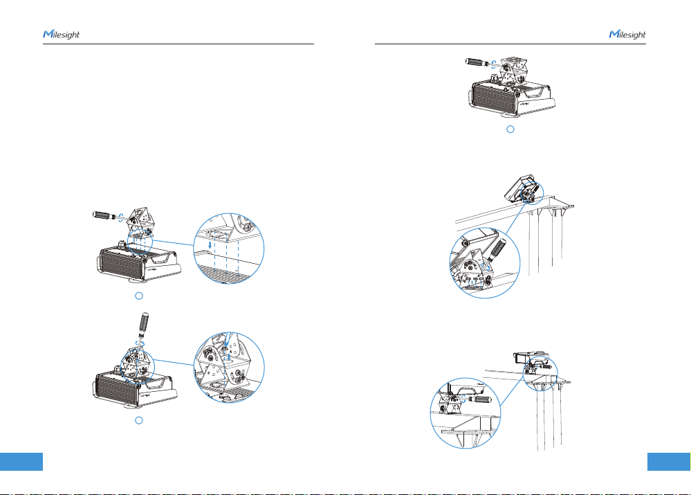
Tips:
1. If necessary, loosen the screws on the rain cover to adjust it to the
appropriate position.
2.The safety latch in the packaging can be used to connect the camera and
secure parts together before installation, preventing them from falling off.
Step 3: Place the assembled camera with the bracket onto the gantry. Use
screws to secure the bracket to the gantry.
Step 4: To adjust the camera angle, loosen the screws indicated on the bracket
as shown in the diagram. The bracket can then be rotated for adjustment. Once
it is properly adjusted, tighten the screws to secure the bracket in place.
1
2
Installation of the Pedestal Mount
Step 2: Loosen the screws on both sides of the bracket as shown in the diagram,
and the bracket will be able to rotate. Align the center hole of the mounting
bracket with the center hole on the bottom of the camera, insert the screws and
tighten them to secure it. After resetting the bracket, tighten the bracket screws.
3

8 19
www.milesight.com
Step 3: According to the instructions on the perforation-assisted stickers, punch
holes at the corresponding installation positions on the vertical plane.
Step 4: Align the bracket with the screw holes on the surface, and secure the
camera bracket using screws.
Step 5: To adjust the camera angle, loosen the screws indicated on the bracket
as shown in the diagram. The bracket can then be rotated for adjustment. Once
it is properly adjusted, tighten the screws to secure the bracket in place.
www.milesight.com
9
Installation of the Wall Mount Bracket
Step 2: Loosen the screws on both sides of the bracket as shown in the diagram,
and the bracket will be able to rotate. Align the center hole of the wall mount
bracket with the center hole on the bottom of the camera, insert the screws and
tighten them to secure it. After resetting the bracket, tighten the bracket screws.
1
Note:
1. Inspect the condition of the installation surface to ensure sufficient support
and strength, avoiding wall detachment or collapse.
2. Before drilling, please ensure to carefully review the hole instructions on the
sticker. The diameter of the three screw holes should be Φ8mm to ensure a
secure installation. The hole intended for cable passage should have a diameter
of Φ26mm to facilitate smooth wiring without any tension or interference.
2
3

www.milesight.com www.milesight.com
10 11
Note:
1.The output options of the multi-functional cables
Yellow IN1
White
Blue
Red
Orange
Black
Gray
IN2
IN3
IN4
GND
ALARM OUT
ALARM OUT
Yellow IN1
Pink RS485 A
Green
Light Blue
Brown
Purple
Red&White
Black&White
RS485 B
Strobe Out1
Strobe Out2
Strobe GND
SYNC
SYNC GND
Cable Connection
Step 1: Unscrew the protective cover at the indicated position on the camera,
remove the protective covers from the two tail wires, connect them to their
respective positions, and tighten the threaded connectors.
The screws in the bracket section can be adjusted to rotate up and down.
The large screw at the bottom can be adjusted to rotate left and right.
1
2

www.milesight.com
12 13
www.milesight.com
2.The output options of the power cables
Red Power+
White
Black
Blue
Power+
Power-
Power-
To connect the power cable to the power adapter, follow these steps:
1. The power cable has 4 connectors: red and white cable connectors, as well as
black and blue cable connectors.
2. Use one terminal with 3 holes to connect the red and white power cables.
There is an additional hole for connecting the positive power supply wire of the
adapter.
3. Use the other terminal to connect the black and blue power cables. Another
hole is designated for connecting the negative power supply wire of the adapter.
Red & White
Power (+)
Power Cable
Black & Blue
Power (-)
Power Supply
Adapter
Step 3: Insert the Ethernet port into the interface and tighten the waterproof
protective cover.
Micro
SD
SIM
Step 2: Remove the waterproof protective cover of the RJ45 interface and take
out the rubber ring. Use an Ethernet cable to connect the following two in
sequence.
RJ45
LAN
Screw Bolt
Fixing Ring
Screw Nut
Rubber Ring
1
23

www.milesight.com
14 15
www.milesight.com
The steps to change the IP of cameras are as below:
1) Start Smart Tools, click the IPC Tools page, then enter the device information,
such as IP address, MAC address, Port number, Netmask, and Gateway, then
all related Milesight network cameras in the same network that will be shown.
2) Select a camera or multiple cameras according to the MAC addresses.
3) Click “Activate” to set the password when using the cameras for the first time
(Password must be 8 to 32 characters long, contain at least one number and one
letter), and set three security questions (If you forget the password, you can reset
the password by answering three security questions correctly).
4) Type the user name and password you set, change the IP address or other
network values, and then click “Modify” button.
5) By double clicking the selected camera or the browser of interested camera,
you can access the camera via web browser directly.
More usage of Smart Tools, please refer to the “Smart Tools User Manual”.
Smart Tools is a software tool which can automatically detect multiple online
Milesight network cameras in the LAN, set IP addresses, and manage firmware
upgrades. It’s recommended to use when assigning IP addresses for multiple
cameras.
19
If the network segment of the computer and that of the camera are different,
please add some 192.168.5.xx(255.255.255.0) for your PC to get access to your
cameras, more details can be found on “Milesight Network Camera Quick Start”.
The camera can be used with the most standard operating systems and
browsers. The recommended browsers are Firefox, Chrome, Safari. More
information about the plugin installation, please refer to the troubleshooting:
5. Milesight-Troubleshooting-Plugin Installation on Windows-IPC
6. Milesight-Troubleshooting-Plugin Installation on MAC
Any changes or modifications not expressly approved by the party responsible
for compliance could void the user’s authority to operate the equipment.
This device complies with part 15 of the FCC Rules. Operation is subject to the
following two conditions:
1. This device may not cause harmful interference.
2. This device must accept any interference received, including interference that
may cause undesired operation.
Note: This equipment has been tested and found to comply with the limits for a
Class B digital device, pursuant to part 15 of the FCC Rules. These limits are
designed to provide reasonable protection against harmful interference in a
residential installation. This equipment generates, uses and can radiate radio
frequency energy and, if not installed and used in accordance with the
instructions, may cause harmful interference to radio communications. However,
there is no guarantee that interference will not occur in a particular installation.
If this equipment does cause harmful interference to radio or television
reception, which can be determined by turning the equipment off and on, the
user is encouraged to try to correct the interference by one or more of the
following measures:

FCC Radiation Exposure Statement:
This equipment complies with FCC radiation exposure limits set forth for an
uncontrolled environment. This equipment should be installed and operated
with minimum distance 20cm between the radiator& your body. This transmitter
must not be co-located or operating in conjunction with any other antenna or
transmitter.
1. Reorient or relocate the receiving antenna.
2. Increase the separation between the equipment and receiver.
3. Connect the equipment into an outlet on a circuit different from that to which
the receiver is connected.
4. Consult the dealer or an experienced radio/TV technician for help.
www.milesight.com
16
This manual suits for next models
1
Other Milesight Digital Camera manuals


