Millennium T3668-80 Setup guide

ABOVE GROU ND POOL SAFET Y
WARN I N G
FAILURE TO HEED THESE WARNINGS CAN RESULT IN PERMANENT INJURY,
PARALYSIS FROM A BROKEN NECK, ELECTROCUTION OR DROWNING.
THIS POOL IS NOT DESIGNED FOR DIVING OR JUMPING!
DANGEROUS INJURY CAN RESULT, SHALLOW WATER!
Your pool contains a large quantity of water, and is deep enough to present inherent dangers to lif
e and health unless the follow
-
ing safety rules are strictly observed. First-time users run the highest risk of injury. Make sure
everyone understands. To insure
your pool is used safely you
must
observe the following safety precautions:
1.
NO JUMPING OR DIVING
The top rail of your pool is not a walkway and must not be used for jumping or diving.
Do not
permit jumping or diving into the pool from a deck or the top rail of the pool. Diving or jumping
into the pool can result in serious injury.
2.
NEVER USE THE POOL ALONE
Never permit the pool to be used unless it is attended by at least one person other than the
bather. Someone should always be available to lend assistance in an emergency.
3.
NEVER LEAVE CHILDREN UNATTENDED
Never leave a child alone and unsupervised in or near the pool—not even for a second. There
is no substitute for constant adult supervision.
4.
NO ROUGH PLAY
Do not permit “rough-playin” in and around your pool. Surfaces can become slippery and
hazardous when wet.
5.
LIGHT THE POOL AT NIGHT
If the pool is used after dusk, adequate lighting must be provided. Illumination in the pool area
must be sufficient to clearly judge pool depth and all features in and around the pool. For light
-
ing recommendations, consult your local licensed electrical contractor
6.
RESTRICT ACCESS TO THE POOL
Do not leave chairs or other furniture beside the pool that could be used by a child to climb
up into the pool. Ladders must be removed whenever the pool is unattended. A fence with a
lockable gate around the pool or yard is strongly recommended and may be required by law in
some jurisdictions.
7.
NO ALCOHOL OR DRUGS
Never drink alcoholic beverages or use any intoxicants which could hinder your judgment and
reflexes.
8.
KEEP YOUR POOL CLEAN AND SANITARY
Your filter system will remove suspended particles from the water and the surface skimmer
will remove insects, leaves and other debris from the water surface. Use the correct pool
chemicals as directed to destroy harmful bacteria and prevent formation of algae. Remember,
unsanitary water is a serious health hazard.
The safety stickers must be installed as per following instructions. Failure to properly install wa
rning labels will void warranty.
Failure to mount these safety labels may subject you to substantial liability in case of injury. Th
ese warning are not to be re
-
moved under any circumstances! If they become discolored or fall off please request replacements wh
ich will be sent at no
charge.
FOLLOW ALL SAFETY INSTRUCTIONS
Read and follow all safety instructions packaged with pool, ladder, deck or any other accessory.
Additional pool safety publications can be obtained by contacting: The Association of Pool &
Spa Professionals (www.apsp.org)
IMPORTANT NOTICE READ BEFORE INSTALLATION!
9.
KEEP OFF TOP LEDGES
Do not walk on top ledges. They can be slippery and they are not a walkway.
10.
POOL COVER SAFETY
The cover must have a tamperproof locking retainer cable that positions the cover around the
pool wall and keeps it securely in place.
Never allow anyone, especially small children on the
cover. Asphyxiation or drowning could result. When purchasing any pool cover, please consult a
swimming pool professional.
11.
ELECTRICAL HAZARD
Never touch or attempt to service electrical equipment, including the filter when your body and/
or the ground is wet.
Electrocution or permanent injury due to high voltage (120V AC) could
result. The pool should be bonded in accordance with Section 680-26 of the National Electical
Code. For further assistance contact your dealer or a local licensed electrician. Do not use pool
during electrical or rain storms.
12.
SAFETY ROPE & POLE
Keep a safety rope 1/4" by 50" with a flotation buoy with an outside diamter of 15".
Have ac
-
cessible in a prominent area by your pool
.
Keep a pole not less that 16 feet (4,88m) long with a
blunt or hook end available at pool side in case of emergencies.
13
.
POOL CHEMICALS
Do not place chlorine, chlorine tablets or sticks directly into skimmer, or winterize your pool wit
h
liquid chlorine.
Damage to the skimmer, pool liner and filter will result. Failure to obey this in
-
struction will void all component warranties. Always follow Chemical Manufacturer’s insturctions
when storing, handling and dispensing pool chemicals.
14.
CHECK FOR DAMAGE
Periodically check your pool and ladder components for damage and wear.
Be sure all screws
are in place. Replace all damaged or worn components and tighten all screws before you use
the pool, deck or ladders. At first sign remove rust and touch up immediately.
15.
POOL PARTS
Never modify the pool or accessories, or remove or drill holes in the pool, deck or ladder com
-
ponents unless instructed.
Your pool wall is made of thin metal, there is an inherent cut hazard
with metal so use gloves during installation. Always use Original Equipment Manufactured parts
for your replacement parts.
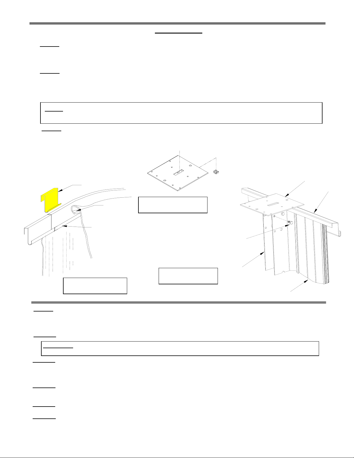
REMEMBER
WATCH
CHILDREN
PLACE SIGN ON
LINER ABOVE WATER
LINE, OPPOSITE ENTRY
TO POOL
PLACE SIGN ON
WALL NEXT TO
POOL ENTRY
R.
12/11
ABOVE GROUND ROUND POOL INSTRUCTIONS

T3668-80
POOL ASSEMBLY AND INSTALLATION MANUAL
Monument Above Ground 52” Round Extruded Wall Pools
Note: Deck and fence accessories shown are optional.
THIS MANUAL EXPLAINS THE CORRECT METHOD TO ASSEMBLE YOUR NEW SWIMMING POOL. READ THESE INSTRUCTIONS AND
STUDY THE ILLUSTRATIONS. ALSO READ INSTRUCTIONS FOR ACCESSORIES SUCH AS FILTERS, LADDERS, ETC. PAY PARTICULAR
ATTENTION TO THE CAUTIONS ON THE FOLLOWING PAGES.
THE MANUFACTURER IS NO T AFFILIATED WITH ANY PROFESSIONAL POOL INSTALLER, THEREFO RE THE MANUFACTURER CANNO T
ASSUME RESPO NSIBILITY FO R ERRO RS IN THE INSTALLATIO N OF YOUR PO OL BY THE INSTALLER O R THE HO MEOWNER. IF Y OU
HAVE THIS PO OL INSTALLED BY O THERS, PLEASE SUPERVISE TO BE SURE Y OUR POOL IS INSTALLED PRO PERLY AND THAT ALL
THE CAUTIO NS LISTED THRO UGHOUT THIS MANUAL HAVE BEEN FOLLOWED. PAST EXPERIENCE O R SHO RT CUTS MAY NO T BE
COMPATIBLE WITH OUR POOLS, FOLLOW THE INSTALLATION MANUAL.
THE MANUFACTURER RESERVES THE RIGHT TO CHANGE OR IMPRO VE ANY ITEM WITHOUT INCURRING ANY OBLIGATION TO MAKE
ANY CHANGES OR IMPROVEMENTS ON ITEMS PREVIOUSLY SOLD AND TO DISCONTINUE MODELS OR CHANGE SPECIFICATIONS AT
ANY TIME WITHOUT NOTICE.
THIS PRODUCT IS SOLD WITH A "LIMITED WARRANTY ". THE TERMS AND CONDITIONS ARE SET FORTH IN THE "LIMITED WARRANTY "
CERTIFICATE PACKED WITH EACH POOL. COPIES OF THE "LIMITED WARRANTY" ARE ALSO AVAILABLE UPON WRITTEN REQUEST.
YOUR LO CAL BUILDING CO DE MAY REQ UIRE O BTAINING A BUILDING PERMIT AND MAY HAVE REQUIREMENTS ON SETBACKS,
BARRIERS, ETC. ANY HO ME BUILT O R PREFABRICATED DECKS SH OULD CONFORM TO THE LOCAL CODES, AND BOCA NATIONAL
BUILDING CODE. THE ELECTRICAL CODE MAY REQUIRE A PERMIT AND INSPECTIO N, AND USE O F G FCI DEVICES O R O THER
CONDITIONS. THE ELECTRICAL INSTALLATION MUST ALSO CONFORM TO ARTICLE 680 OF THE NATIONAL ELECTRIC CODE. INSTALL
THE FILTER AND PUMP IN ACCORDANCE WITH THE MANUFACTURERS INSTRUCTIONS. . ARTICLE 680 STATES THAT YOU MUST
BOND THE SWIMMING POOL PUMP TO THE SWIMMING POOL. THIS CAN BE DONE BY ATTACHING A #8 COPPER WIRE FROM THE
BONDING LUG ON THE PUMP TO AN UNPAINTED METAL SURFACE ON THE POOL WALL OR BOTTOM CLIP.
THE INSTALLATION OF AN ABOVE GROUND SWIMMING POOL WILL USUALLY REQUIRE THREE PEOPLE TO HELP ASSEMBLE IT.
DANGER: THIS POOL, EVEN IF SUPPLIED WITH A DEEP AREA, CONFORMS TO THE NATIONAL SWIMMING POOL INSTITUTE
STANDARDS FOR A TYPE O, NON-DIVING POOL. DIVING, SLIDING OR JUMPING INTO THE POOL MAY CAUSE PARALYSIS, DEATH OR
PERMANENT INJURY.

2
DANGER
1. DO NOT DIVE OR JUMP INTO Y OUR POOL. DO NOT USE A POOL SLIDE ON THIS POOL. YOUR POOL CONTAINS SHALLOW WATER
AND IS NOT DESIGNED FOR HEADFIRST ENTRY (DIVING OR SLIDING) OR JUMPING. DIVING, SLIDING OR JUMPING CANRESULT IN A
BROKEN NECK IF YOU STRIKE THE POOL. THIS CAN RESULT IN PARALYSIS, DEATH OR PERMANENT INJURY . INFORM ALL FAMILY
AND GUESTS OF THESE RULES AND POINT OUT WARNING LABELS.
2. IT IS NECESSARY TO MAINTAIN A 4’ HIGH BARRIER TO REDUCE THE CHANCE OF A CHILD ACCESSING AN UNSUPERVISED POOL.
THE BARRIER MAY BE A FENCE, WALL, OR COMBINATION TH EREOF WHICH COMPLETELY SURROUNDS THE POOL. BARRIERS
MUST COMPLY WITH THE LOCAL BUILDI NG CODE, BOCA NATIONAL BUILDING CO DE OR THE “CONSUMER PRODUCT SAFETY
COMMISSION” BARRIER STATEMENT. THE FO UR FOOT HIG H PO OL WALLS USUALLY PROVIDE THIS BARRIER, HOWEVER IF THE
POOL IS LESS THAN 48” ABO VE GRADE, OR HAS BUTTRESSES (OVAL POOLS), YOU MAY NEED ADDITIONAL FENCING TO PROVIDE
THIS BARRIER. CONSULT WITH Y OUR BUILDING O FFICIAL FO R SPECIFIC REQ UIREMENTS. FENCING O PTIONS ARE AVAILABLE
FOR YOUR POOL, PLEASE CONTACT YOUR POOL DEALER.
3. Y OU MUST MAINTAIN A 5’ WIDE “CLEAR ZONE” AROUND TH E POOL AND DECK OR FENCING. DO NOT ALLOW TOYS, CHAIRS,
TABLES OR SIMILAR CLIMBABLE OBJECTS IN THIS “CLEAR ZO NE”, ENABLING CHILDREN TO CLIMB AND G AIN ACCESS TO THE
POOL. THE FILTER EQUIPMENT MUST ALSO BE LOCATED OUTSIDE OF THE “CLEAR ZONE”.
4. YOU MUST RAISE AND LATCH, OR SECURE YOUR POOL LADDER OR POOL ENTRANCE WHEN THE POOL IS NOT IN USE.
Adherence to the above items will reduce the frequency of preventable child drownings in swimming pools.
WARNING
1. YOUR POOL IS SUPPLIED WITH WARNING SIGNS, WHICH MUST BE AFFIXED TO THE POOL AS SPECIFIED. IF YOU BUILD A DECK,
THE TWO AREA SIGNS MUST BE AFFIXED TO THE DECK AT THE POINT OF ENTRY, VISIBLE TO PEOPLE ENTERING THE POOL
AREA. FAILURE TO INSTALL OR IMPROPER LOCATION OF SAFETY INFORMATION WILL SUBJECT YOU AND/OR THE INSTALLER
TO LIABILITY ARISING FROM INJURY CLAIMS.
A. NO DIVING COPING: ( TWO SUPPLIED ) THESE ARE TO BE INSTALLED ACROSS THE POOL FROM THE POINT OF ENTRY,
AND HAVE ONE SECTION OF REGULAR COPING BETWEEN THEM.
B. COPING WITH INTERNATIONAL LOGO: THIS ONE COPING IS TO BE INSTALLED AT THE POINT OF ENTRY, EITHER ADJACENT
TO THE “A” LADDER, UNDER THE IN POOL LADDER, OR IN THE CENTER OF A DECK.
C: DANGER AREA SIGN WITH LOGO: ( T1440) THIS SIGN MUST BE INSTALLED AT THE POINT OF ENTRY, FACING ALL USERS
AS THEY ENTER THE PO OL. IF Y OUR POOL HAS A FENCE, THE SIG N IS TO BE FASTENED TO THE FENCE, ADJACENT TO
THE LADDER OR ENTRANCE. IF Y OUR POOL DOES NOT HAVE A DECK O R FENCE, ATTACH THE SIGN TO THE EDGE OF THE
COPING ADJACENT TO THE LADDER. THE SIGN MUST BE VISIBLE TO ALL USERS AS THEY ENTER THE POOL AREA.
D. CAUTION - SAFETY RULES SIGN: (1445) THIS SIGN MUST BE ATTACHED TO THE FENCE DIRECTLY BELOW THE DANGER
SIGN OR IF YOU DO NOT HAVE POOL FENCING, ON THE COPING NEXT TO THE DANGER SIGN.
If any signs are missing or damaged contact the customer service department for replacements.
CAUTION
1. DECK SURFACES MAY BECOME SLIPPERY WHEN WET. DO NOT RUN OR DIVE INTO THE POOL FROM THE DECK.
NOTE: SUNTAN LOTIONS AND OILS MAY CAUSE POOL COMPONENTS TO BECOME SLIPPERY.
2. EACH MONTH CHECK THE POOL WALL FOR DETERIORATION OR LEAKAGE, ESPECIALLY AT THE SKIMMER AND RETURN
FITTINGS. THE SKIMMER AND RETURN GASKETS SHOULD BE REPLACED EACH SPRING TO PREVENT LEAKAGE.
DETERIORATION CAN WEAKEN THE POOL WALL WHICH COULD RUPTURE, RELEASING THE POOL WATER WHICH COULD CAUSE
BODILY HARM AND PROPERTY DAMAGE.
3. FOR NIGHTIME USE, YOU MUST PROVIDE LIGHTING TO ILLUMINATE THE POOL, SAFETY SIGNS, AND DECK SURFACES. LIGHTING
MUST COMPLY WITH ARTICLE 680 OF THE NATIONAL ELECTRIC CODE. IT IS IMPORTANT THAT USERS BE ABLE TO SEE THE
SHALLOW DEPTH OF THE POOL AT ALL TIMES.
4. THE FOLLOWING BASIC LIFESAVING EQUIPMENT MUST BE ON HAND AT ALL TIMES:
A. A LIGHT BUT STRONG POLE ( SHEPHERD’S CROOK ) NOT LESS THAN 12’ LONG.
B. A 1/4” THROWING ROPE, AS LONG AS 1 1/2 TIMES THE MAXIMUM WIDTH OF THE POOL, WHICH IS ATTACHED TO A COAST
GUARD APPROVED FLOTATION DEVICE SUCH AS A RING BUOY.
C. A TELEPHONE SHOULD BE NEARBY WITH A LIST OF EMERGENCY TELEPHONE NUMBERS, SUCH AS POLICE, & AMBULANCE

5. ADDITIONAL POOL SAFETY RELATED PUBLICATIONS ARE AVAILABLE FROM THE FOLLOWING:
ASSOCIATION OF POOL & SPA PROFESSIONALS CONSUMER PRODUCT SAFETY COMMISSION
2111 EISENHOWER AVE. WASHINGTON, DC 20207
ALEXANDRIA, VA 22314-4695
IMPORTANT INSTALLATION ITEMS
1. LEVELNESS; POOL MUST BE LEVEL WITHIN 3/4”. UNLEVEL POOLS PLACE EXTREME FORCES ON THE POOL WHICH MAY DEFORM.
2. WALL CLOSURE; THE POOL WALL MUST BE FASTENED TOGETHER PROPERLY WITH BOTH BARS AND FASTENERS IN ALL HOLES.
OMITTED BARS OR FASTENERS CAN CAUSE THE WALL TO RUPTURE, DESTROYING THE POOL AND INJURING PEOPLE.
3. SAND COVE; THIS SUPPORTS THE LINER AND MUST BE PACKED SOLID. IF IT COMPRESSES, SHIFTS OR ERODES THE LINER MAY
RUPTURE, RELEASING ALL THE WATER AND DESTROYING THE POOL AND INJURING PEOPLE.
4. THESE POOLS ARE NOT DESIGNED TO BE BURIED. THE GROUND FORCES CAN COLLAPSE THE POOL INWARD. FOR SEMI IN-
GROUND INSTALLATIONS, CONTACT YOUR DEALER FOR DOCUMENT T3964.
5. DO NOT LOCATE YOUR POOL NEAR STRUCTURES SUCH AS A HOUSE, GARAGE, ETC. AS PEOPLE COULD DIVE OR JUMP INTO
THE POOL RESULTING IN DEATH OR PERMANENT INJURY.
6. ALTHOUGH THERE ARE RELATIVELY FEW PARTS IN YOUR POOL, NONE MAY BE OMITTED IN ASSEMBLY. EACH PART SUPPLIED
IS AN IMPORTANT PART AND IF OMITTED, MAY CAUSE POOL FAILURE. CHECK ALL PARTS AGAINST THE PARTS LIST.
WARNING: Do not exceed the following torque values for the noted fasteners:
1/4” - 20 S. S. Fasteners 75 (in. lbs.)
3/8” - 16 S. S. Fasteners 236 (in. lbs.)
3/8” - 16 Aluminum Fasteners 143 (in. lbs.)
TOOLS AND MATERIALS
PHILLIPS SCREWDRIVER #2 HAND TROWEL EXTENSION CORD HAMMER RAKE
SLOTTED SCREWDRIVER #2 GARDEN HOSE & NOZZLE STRING LINE PLIERS
SOCKET WRENCH & SOCKETS 50’ TAPE MEASURE HAND TAMPER TORQUE WRENCH
TRANSIT OR FARM LEVEL ELECTRIC DRILL & BITS GARDEN SHOVEL WRENCHES
1 LONG STRAIGHT 2 X 4 14’ LONG 1 ROLL DUCT OR FABRIC TAPE
25 WOOD STAKES I CAN WHITE SPRAY PAINT
SAND AND BLOCK CHART SAND 2” x 8” x 16” 4” x 8” x 16”
POOL SIZE TONS YARDS PATIO BLOCKS CAP BLOCKS
15' 2 1 1/4 10 NOTE: Sand must be
masons or bar sand and
be free of foreign objects
18' 2 1/2 1 3/4 12
21' 3 1/2 2 1/4 14
24' 4 1/2 3 16
27' 5 3/4 3 3/4 18
30’ 6 5 20
SELECTING THE POOL SITE
1. Check your local building codes and acquire proper building permits. For poor soil conditions consult a
professional engineer.
2. The pool site must be absolutely level and solid. The area must be free from stones and roots.
3. To protect the pool from chemicals and foreign matter in the soil, you may use a ground cover under the sand
base.
Do not install your pool on asphalt, tar paper, grass, wood, gravel, clay, or concrete, or treated soils.
4. Position your pool away from trees, overhead wires, structures such as a house or garage or septic field.
GROUND PREPARATION
Your pool must be installed on a solid level surface. Posi tion stakes as shown on figure 1 and use a farm level or
transit to level the area shown. Remove all grass, roots and stones. Start at the lowest spot level outwards, do not fill
in low spots. The area must be absolutely level. The following table refers to Figures 1 and 3 on the next page.
ROUND POOLS LINE “1” LINE “2”
15’ - 0” 8’ - 6” 7’ - 6”
18’ - 0” 10” - 0” 9’ - 0”
21’ - 0” 11’ - 6” 10’ - 6”
24’ - 0” 13’ - 0” 12’ - 0”
27’ - 0” 14’ - 6” 13’ - 6”
30’ - 0” 16’ - 0” 15’ - 0”
3

SECTION II - POOL CONSTRUCTION
4
Step 3: See Figures 3 and 4. Place the required amount of s and in the pool area. Starting at the bottom clip on the
downwind side of the pool, attach the upright slat to the bottom clip. Be sure the machine screw is to the inside of the
pool. Working in a counter clockwise direction slide a wa ll slat onto the upright slat. The wall slat should be held
about 30 degrees from the upright slat wh ile sliding together. Then when seated, rotate the wall slat against the wall
angle. The skimmer slat should be located between the fi rst two round side upright slats as you work around the
pool. Do not locate the skimmer under the patio. The return slat must be located within 15 panels to the left of the
skimmer as you face the pool.
Be careful not to let the wall fall over during assembly. The walls must remain plumb. If the wall falls over,
disassemble fallen section and start again.
.
After the pool wall is assembled, check the dimensions of the pool to insure that it has not shifted during assembly.
Step 4: See Figure 5 and Detail 5a. Install the skimmer throat gasket to each side of the pool wall and attach the
skimmer to the wall as shown using hardware provided with the skimmer. Mount the skimme r at the center with only
two (2) pan head screws at this point. Refer to skimmer instruction sheet.
Loosen the nuts from the bottom clip / upright slat attachment. If you are installing a walk deck on this pool
Do Not completely remove the nut from the bolt. You will need this bolt to attach the walk deck posts.
CAUTION: Installation of the wall in any other
manner than precisely described above will cause
extensive damage to the pool and may result in
injury or death to those people in or around your
pool.
FIGURE 2
FIGURE 1
STAKE L00033A
LINE 2
LINE 1 LEVEL
Step 1: Parts Identification:
See figures in bill of material
packet. Check for
installation addendums.
Step 2: See Figure 1 and
2. Mark line “2” as shown in
the table on page 3. Create
a circle on line “2” by sliding
the wall channels into the
bottom clips. Place a 2”
thick patio block under each
bottom clip. If the bottom
wall channel is on soft
ground, place additional
blocks in a pyramidal shape
under the bottom clips for
support. Also place
additional blocks under the
wall channel where needed.
Dig 2” down for each block.
The top of the top block
must be at grade level.
Place a stake adjacent to
each wall channel to keep
the circle in position during
installation.
GROUND
PREPARATION AREA:
REMOVE ALL GRASS,
ROOTS, STONES AND
DEBRIS
TRANSIT
L00034A
SMALL
BOTTOM
CLIP
FOLLOW LINE 2
STAKE 2” X 8” X 16”
PATIO BLOCK
BOTTOM WALL
ANGLE
STACKING
PATTERN FOR
POOR SOIL
If a pool fence or deck is to be installed, read those manuals before proceeding. Check care
and maintenance manual for proper placement of safety information.

Step 5: See Figure 6. Spread the sand across the entire botto m of the pool. Moisten and tamp the sand to provide
a solid base. The sand base must be 2” deep after tampi ng. The sand should be moistened and trowel to a smooth
finish. Create a 6” radius cove along the wall as shown. This cove must also be tamped solid to prevent shifting.
WARNING: Failure to use the sand or sand equivalent and shape it as specified will void all warranties on the pool
and liner.
FIGURE 3
W00036
5
DIMENSIONS
ARE TO TOP
OF WALL
WALL
WALL
CHANNEL
50”
44”
6
”
RADIUS
2
”
SAND BASE
FIGURE 6
W00026B
NOTE: THE SKIMMER
THROAT GASKET MUST
SANDWICH THE WALL. I.E.
ONE FLAP OF THE GASKET
MUST BE ON THE INSIDE OF
THE WALL AND THE OTHER
ON THE OUTSIDE.
FIGURE 4
W00037
WALL SLAT
UPRIGHT
SLAT
SMOOTH SIDE
AGAINST
14” – 20 SS
HEX NUT
BOTTOM
CLIP
¼” – 20 X ¾” SS
MACHINE SCREW
WALL ANGLE
WALL SLAT
ROTATE INTO
PLACE
BOTTOM CLIP
UPRIGHT
SLAT
W00040
SKIMMER
DETAIL 5A THROAT
GASKET
WALL

BEADED LINERS
Step 6: See Figure 6. Place the bead receiver on the wall. Tape the joints of the bead receiver using fabric
tape to protect the liner. Place the top clips on the upright s. Attach the top clips to the uprights as shown in
figures 7 and 7A.
Step 7: Remove the liner from the carton and unfold into the pool. Be careful not to drag, abrade or snag
the liner. Spread the liner out over the entire botto m of the pool. Raise the liner side wall and place the
bead into the bead receiver. See Figure 6. Bead must be fully seated in the receiver to prevent it from
coming out later. When filling begins, check the bead frequently.
NOTE: If the liner is exposed to the sun for a long time , it will stretch and cause wrinkles. This can be
avoided by waiting until dusk or by spraying cold water on the liner during installation.
Step 8: Smooth all the wrinkles out on the bottom of the liner. To remove wrinkles, always pull the liner
firmly but gently. No sharp tugs ! Be certain liner is centered. Time spent removing wrinkles and aligning
the liner will give you a neater looking and easily maintained pool.
TOP CLIP BEAD
#10 CAPTIVE
6
DUCT TAPE NUT RECEIVER
FIGURE 7A
BEAD
RECEIVER
LINER
BEAD
LINER
WALL
L00036C
#12 X ½” HEX
HEAD SCREW
4 PER UPRIGHT
(USE LOWER
SET OF HOLES
IN TOP CLIP)
UPRIGHT
FIGURE 7 SLAT
FIGURE 6 A00031
W00023 WALL SLAT
Step 9: Begin to fill the pool with water. Use a slow st ream of water and fill approximately 1 1/2” deep. Make
sure the fit of the liner is correct, smooth out any wrinkles in the pool bottom. If installing a deck, do not fill
more than 12” until the deck is installed.
Step 10: Fill the pool with 4” to 6” of water.
WARNING: The pool must not be more than 3/4” out of level. If the pool is not level, drain the water and
level the structure. Any non-compliance with this requirement will void all warranties.
Step 11: Locate the safety warning copings as described and as shown at the back of this manual. Attach the
coping, as shown in figure 8, to the outermost set of holes in the top clip. Measure the distance from the coping
to the water surface at several points around the pool to be certain that the pool is still level.
Step 12: At each upright, attach the coping covers as shown in Figures 9A and 9B based on the type of pool
you are installing.
Step 13: Fill the pool until the water level is 3 inches below the return hole.
Step 14: Follow the instructions for the f iltration system, skimmer and return that are supplied with the filter.
See Figure 10 for a reference only.

COPING COVER ATTACHMENT FOR ALUMINUM POOLS
#10 X ½” SELF
TAPPING SCREWS ATTACH COPING TO
OUTER SET OF HOLES
ROUND END
COPING
FIGURE 8
W00053
TOP CLIP
ALUMINUM POOLS
WITH ALUMINUM COVERS
COPING
COVER
#10-24 X 5/8”
MACHINE SCREW
UPRIGHT
SLAT
BEND TABS TO
SECURE TO
COPING
ALUMINUM POOLS
WITH RESIN COVERS
FIGURE 9A
7
A00028A
#12 X 1”
HEAX HEAD
SCREWS
ONE PER SIDE
#10-24 X 5/8”
MACHINE
SCREW
FIGURE 9B
A00028B

8
POOL WALL
SKIMMER ASSEMBLY
TEFLON
TAPE
TEFLON TAPE LINER
HOSE
ADAPTER
FACE PLATE
GASKET
HOSE
ADAPTER
FIGURE 10 FACE
PLATE
SCREW
LOCKNUT
FACE
PLATE
W00024
FIBER
WASHER LINER
SANDWICH
GASKET POOL WALL
RUBBER GASKET
WALL FITTING
DIRECTIONAL BALL DIRECTIONAL
BALL FITTING
(POINT OPENING AWAY
FROM SKIMMER)
RETURN ASSEMBLY
DANGER: When a filter or any other electrical device is added to this pool, it is the responsibility of the
purchaser to take all necessary precautions as set forth in article 680 of the National Electrical Code and
local electrical codes. Failure to comply with th is requirement may result in a dangerous or hazardous
electrical condition, which may cause bodily injury or death.
C
D
A
A
B POOL
WITH “A”
FRAME
LADDER
AND
FRNCE
FIGURE 11A
POOL WITH
LADDER DSA00004
C
NOTE: Refer to Page 2, Warning section for Label Number Designations

Step 15: Attach the remaining safety warning signs as described and shown in Figures 11A and 11B. If
installing a fence or deck refer to those manuals for proper placement of safety information.
Step 16: Fill the pool up to the center of the skimmer, make sure that all fasteners are tightened properly
and your pool is correctly assembled. Please read the “Sensible Way to Enjoy Your Pool” booklet and
enjoy years of swimming and relaxation.
AA
WATER SIDE
DANGER
B
B
C & D
A
C
D
DANGER
CAUTION:
DECK SIDE POINT OF
ENTRY C & D
B
A A
SA00003B
FIGURE 11B
ADDITIONAL DANGER SIGN
(SEE SIDE DECK MANUAL)
B C & D
POINT OF
ENTRY
A
POINT OF
ENTRY
WARNING: After completion of the pool, the pool must never be drained to less than 1/2 full. Damage
to the structure and/or liner ma
y
result.
9
Table of contents
Other Millennium Swimming Pool manuals
Popular Swimming Pool manuals by other brands

Bestway
Bestway Power Steel Series owner's manual

Procopi
Procopi Piscines Bois ODYSSEA OCTO installation instructions

GRE
GRE KITPROV818 manual

POLYGROUP LIMITED
POLYGROUP LIMITED PRO-SERIES ABOVE GROUND RECTANGULAR QUICK... owner's manual

Piscine Solide
Piscine Solide V35048 installation manual

Weka
Weka 593.4050.20 Series ASSEMBLY, USER AND MAINTENANCE INSTRUCTIONS