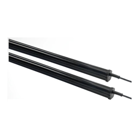
Miller Edge ME123 User manual

www.milleredge.com info@milleredge.com 800-220-3343 1/4
The Miller Edge ME123 Style Sensing Edge is a UL Recognized Component that meets the UL 325 requirement. Compatible with most operator brands,
Sensing Edges are touch sensitive sensors designed to protect entrapment zones along the leading edge of automated doors or other motorized equipment.
Consult your manual for detailed instructions about connecting to the motor.
CONTENTS
• Miller Edge ME123 Sensing Edge
REQUIRED
• 18-22 gauge wire
• Miller Edge mounting channel
• Mounting channel mounting screws
OPTIONAL
• Connection methods:
Miller Edge wireless
edge transmitter/receiver
Coil cord
Retracting reel
Junction box(es)
• Signature Module (SM-101, SM-102)
SUGGESTED
• Operator installation manual
• Edge Tester (MET-101)
• Ohm meter (capable of measuring 10K)
1. INSTALLATION SETUP
1. All Miller Edge sensing edges are inspected and tested prior to shipment to ensure quality. Upon opening the shipping box, inspect your sensing
edge and wiring for shipping damage. If the shipping container appears to be damaged, please notify carrier immediately.
2. Un-box and lay the sensing edge out straight. This will allow the edge to relax and return to its original shape.
INSTALLATION INSTRUCTIONS
SENSING EDGE
ME123
IMPORTANT
Read and understand all instructions before beginning installation. All Miller Sensing Edges are inspected and tested before being
shipped to ensure against damage. If the shipping container appears to be damaged, please notify the carrier immediately.
2A.MOUNTING CHANNEL INSTALLATION (DOORS)
1. Slide the edge into the mounting channel.
2. Align the edge and mounting channel to the leading edge of the door.
3. Adjust the close limits on the motor for a maximum compression of
.25” (6 mm).
4. Attach the channel to the by drilling self-tapping screws into the
mounting channel, starting 3” (7 cm) from the ends and spaced
approximately every 24”.
TECH TIP
To compensate for floor irregularities, gently curve the mounting channel
up or down to close any gaps between the edge and the floor, wall, or
other permanent fixture.
2B.MOUNTING CHANNEL INSTALLATION (OTHER)
1. Attach the channel to the by drilling self-tapping screws into the
mounting channel, starting 3” (7 cm) from the ends and spaced
approximately every 24”.
2. Slide the edge into the mounting channel.
3. Adjust the close limits on the motor for a maximum compression
of .25” (6 mm).
MOUNTING CHANNEL STYLES &
POSSIBLE HARDWARE PLACEMENT
ME123-C7
PVC
ME123-C1
PVC
ME123-C3
PVC
1.5”H x 2”W
ME123-C2175
PVC
ME123-C
PVC
1.5”H x 2”W
ME123-CA3
Aluminum
ME123_Inst_20180926

www.milleredge.com info@milleredge.com 800-220-3343 2/4
ME123 SENSING EDGE
WIRELESS METHOD REQUIRED
Miller Edge wireless edge transmitter/receiver system
INSTALLATION
1. Consult the Miller Edge transmitter/receiver installation
instructions for wiring of the sensing edge.
2. For proper connection to operator inputs, please consult
the operator manual.
COIL CORD METHOD
Note: For specific operator input connection diagrams
and instructions, please consult your operator manual.
REQUIRED
Junction boxes (2) Mounting screws
Wire end caps 18-22 gauge wire
INSTALLATION
1. Mount the first junction box on the end stile or bottom bar
of the door.
2. Run the sensing edge lead wire into the junction box.
3. Mount the second junction box on an adjoining wall,
midway between the floor and the operator.
4. With the door in the closed position, secure the coil cord
to the first junction box.
5. Then run it, fully stretched, to the second wall mounted
junction box so the stretched length is equal to one-half of
the door opening.
6. Secure the coil cord into the wall junction box and trim the
coil cord. This assures the excess coil cord will not get
caught or hang in the opening of the door.
7. Secure 18-22 gauge wire into the second wall-mounted
junction box and hard wire to the operator sensing edge
terminals.
RETRACTING REEL METHOD
Note: For specific operator input connection diagrams
and instructions, please consult your operator manual.
REQUIRED
Junction box (1) Mounting screws
Wire end caps 18-22 gauge wire
INSTALLATION
NOT SUITABLE FOR MONITORED SENSING EDGES
1. Mount the junction box on the end stile or bottom bar of
the door.
2. Run the sensing edge lead wire into the junction box.
3. Mount the retracting reel on an adjoining wall, near the
operator.
4. With the door in the closed position, secure the retracting
reel cable to the junction box. The cable should freely
extend, without rubbing, in and out of the retracting reel for
the duration of the open/close cycle.
5. Using the 18-22 gauge wire, hardwire the retracting reel to
the sensing edge terminals of the operator.
3. SENSING EDGE INSTALLATION

www.milleredge.com info@milleredge.com 800-220-3343 3/4
TECH SUPPORT
For additional assistance, contact Miller Edge Tech Support: 800-220-3343
4. TROUBLESHOOTING
SENSING EDGE SHIFTING
REQUIRED
• (2) #6 x 1/2” self-drilling hex head screws
• 1/4” standard socket
INSTALLATION
To prevent the Sensing Edge from shifting within
the mounting channel:
1. Mount the Miller Edge mounting channel and
Sensing Edge in accordance with Step 3:
Sensing Edge Installation.
2. Insert self-drilling screws horizontally
into the face of the mounting channel T-Slot
2”-6” from the end of the interior side of the
door.
3. Repeat step 2 on the opposite end of the
inside of the door.
Caution: Keep all tools away from the body of
the Sensing Edge.
ME123 SENSING EDGE
BLINKING =
LOW BATTERY
DC(T3) 10K(T2) NON-TERM
POWER ON / AUTO OFF
EDGE TESTER
800-220-3343
www.milleredge.com
Model:MET-101
INSTRUCTIONS
TurnTester ON
Select Switch Position
Connect Edge ToLeads
EDGE ACTIVE
/FAULT
GREEN = PWR/OK
RED = EDGE ACTIVATED
BLINKING RED = FAULT
10K
EDGE TESTER (MET-101)
BLINKING =
LOW BATTERY
DC(T3) 10K(T2) NON-TERM
POWER ON / AUTO OFF
EDGE TESTER
800-220-3343
www.milleredge.com
Model:MET-101
INSTRUCTIONS
TurnTester ON
Select Switch Position
Connect Edge ToLeads
EDGE ACTIVE
/FAULT
GREEN = PWR/OK
RED = EDGE ACTIVATED
BLINKING RED = FAULT
10K
OHM METER
TECH TIP
To determine sensing edge termination, note
the colored band on the sensing edge cable:
BAND COLOR TERMINATION TYPE
Green 8.2K Ohm Resistor T1
Blue* 10K Ohm Resistor T2
Red* Diode Capacitor T3
White Capacitor T4
Orange 6.8K Ohm Resistor T5
Purple 270K Ohm Resistor T6
None Non-terminated –
*Most Commonly used.
SENSING EDGE CHECK
SUGGESTED
• Edge Tester (MET-101)
• Ohm meter (capable of measuring 10K)
TEST
Test the sensing edge for function:
1. To verify the termination of a 10K ohm (T2) sensing edge, use a Edge Tester (MET-101) or an ohm meter; the edge resistance should
be ~10K ohms (9.5-10.5K).
2. To verify the termination of a diode capacitor (T3) sensing edge, use a Edge Tester (MET-101); this is the only method to test a T3
sensing edge.
3. Press the Sensing Edge to confirm the resistance is less than 5 ohms.
MOUNTING
CHANNEL
T-SLOT
SENSING
EDGE T
2”-6”
#6 X 1/2” HEX HEAD
SELF-DRILLING SCREW
INTERIOR SIDE OF DOOR

www.milleredge.com info@milleredge.com 800-220-3343 4/4
GENERAL SPECIFICATIONS
Length Per spec to +/- .25” or 6 mm
Lead Wire 2 ft. length of 18 or 22 gauge SJTO
Sensitivity Nominal 6-11 lbf
Electrical Maximum 24 VAC/DC, 1/2 amp
Contact Element Alumaglas®
Materials Extruded flexible PVC
Temperature Rating -30°F to +155°F or -34°C to +68°C
Warranty 1 year
Ratings UL 325 Recognized Component
ELECTRICAL CONFIGURATION OPTIONS
• 2-Wire 8.2K Ohm Resistive (T1/green band)
• 2-Wire 10K Ohm Resistive (T2/blue band)
• 2-Wire Diode Capacitor (T3/red band)
• 2-Wire Capacitor (T4/white band)
• 2-Wire 6.8K Ohm Resistive (T5/orange band)
• 2-Wire 270K Ohm Resistive (T6/violet band)
• 2-Wire Non-Monitored
• 4-Wire Monitored
• Bumper (no sensor)
MAINTENANCE
It is strongly recommended that end users test the Sensing Edge at least once per month. Check the Sensing Edge for cuts, loss of sensitivity, or water
damage. Also check for signs of damage to cables or connection points. Starting 2” from the ends, compress the Sensing Edge 1/2” throughout the
length of the edge and observe that it sends an electric signal to the controls.
REPLACEMENT
To replace your Miller Edge Sensing Edge, contact your Miller Edge sales representative. Attempt to repair your Miller Edge sensing edge is not
recommended and will void the manufacturer warranty.
WARRANTY
Miller Edge, Inc. will replace within one year of shipment from factory any Sensing Edge subject to normal use, which is found to have defective
materials or workmanship, as determined solely by our factory representative. Replacements will be shipped to you freight collect. This warranty is
void where evidence of misuse or abuse is present.
ACCESSORIES
Contact your Miller Edge sales representative for sensing edge accessories:
MOUNTING CHANNELS JUNCTION BOXES COIL CORDS RETRACTING REELS TRANSMITTERS/
RECEIVERS
MODULES
ME123 SENSING EDGE
Table of contents
Other Miller Edge Accessories manuals
Popular Accessories manuals by other brands
LMI Technologies
LMI Technologies Gocator 2300 Series user manual

Tower Hobbies
Tower Hobbies T19003 Safety and instruction manual
Keating Of Chicago
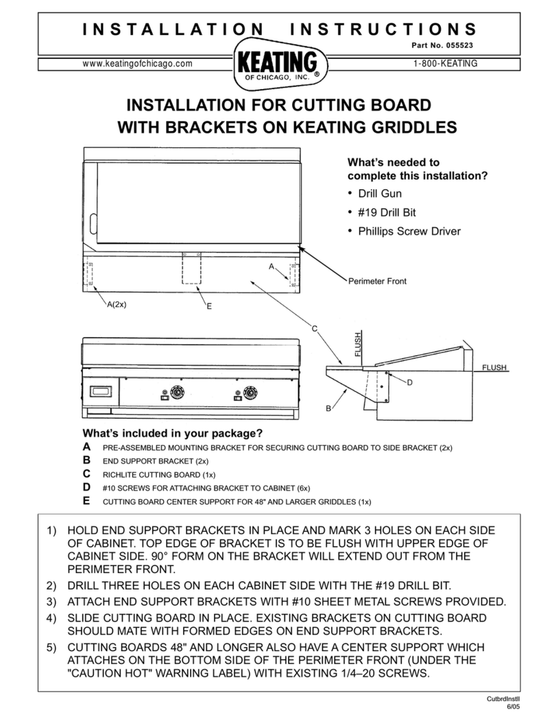
Keating Of Chicago Cutting Board with Brackets 055523 installation instructions

Philips
Philips SAC2520W/10 user manual

Monoprice
Monoprice 33124 user manual

Philips
Philips SVC1215/10 user manual
