Miller JUMBO User manual

Page 1
Operation and maintenance manual
Jumbo Pump
OPERATION AND
MAINTENANCE MANUAL
JUMBO PUMP
MILLER SALES & ENGINEERING
3801 N. Highway Drive
Tucson, Arizona 85705
1-800-666-8320
mseinc.net
Info@mseinc.net

Page 2
Operation and maintenance manual
Jumbo Pump
TABLE OF CONTENTS
3 Safety and Warning Instructions
3 Warranty
3 Description of the Product
3 Operation
4,5 Assembly
5 Fluids and Substances
5 Maintenance
6 Technical Data
6 Performance Curve
7 Parts Drawing

Page 3
Operation and maintenance manual
Jumbo Pump
SAFETY AND WARNING INSTRUCTIONS
Always follow the safety and warning instructions. Operation and Maintenance must comply with local regulations
and accepted codes of practice, including wearing of Personal Protective Equipment (PPE). The following
instructions apply to the standard version of the product operating in normal conditions. The data in the
documentation and the product itself may be subject to modification without the manufacturer being obliged to give
prior notice. Failure to comply with the instructions herein, improper use of the product or unauthorized modification
to the product shall void all forms of warranty, while the manufacturer shall not be held responsible for any damages
resulting to persons or property.
Before performing any work on the product, always make sure that the electrical parts of the system on which work
is to be carried out are disconnected from the electric power source. Any operating, servicing, repair and/or
dismantling of the product may only be undertaken by specialized personnel possessing the necessary qualifications
and equipped with adequate tools. Such personnel must have become fully familiar with the contents of these
instructions and any other documentation supplied with the product.
WARRANTY
Tru‐Flo Pumping Systems warrants the product to be free from defects in workmanship and materials under normal
use and service for a period of twelve calendar months from the date of delivery or 1000 hours of operation,
whichever occurs first.
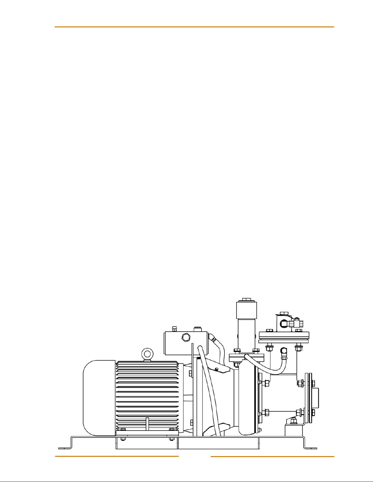
DESCRIPTION OF THE PRODUCT
The Jumbo pump has been specifically designed for the underground mining industry and is supplied with a flotation
suction strainer intended for use in sumps at the development face. The strainer floats on the water and draws from
one inch below the surface, thereby reducing shotcrete fibers in the pumping system.
OPERATION
PRIMING
The water from the drilling equipment’s hydraulic coolers (that normally drains to the ground), is piped through the
venturi on the Jumbo pump, producing a vacuum to lift water from the face to prime the pump. (Vacuum prime: ‐60
to ‐80kPa, 20 to 26Ft head lift). This lifts the venture ball off its seat, allowing air to be displaced from the vacuum
canister and pump casting. The outlet reflux ball seals on its seat to prevent air being drawn into the vacuum canister.
When the air has been displaced, a vacuum is present in the canister and the pump casting, which draws the water
into the pump. After the pump has primed, normal operation will occur. At this point the venturi ball is drawn on to its
seat to prevent the pump from sucking air from the air discharge port.
When the sump has been emptied, the pump will continue to run until enough water is available to re‐prime itself
and the above process begins again.

Page 4
Operation and maintenance manual
Jumbo Pump
MECHANICAL SEAL
The pump is fitted with a tungsten/tungsten single mechanical seal which is located in the seal chamber on the back
of the pump casting. This chamber is filled with oil, which cools and lubricates the seal which in turn allows the pump
to run‐dry for 3 to 4 hours without damage to the seal faces.
PUMP PERFORMANCE ADJUSTMENTS (Shimming)
After the pump has been operating for a long period of time, the performance will gradually decline and the wear
plate will require adjustment to maintain discharge flow.
When the impeller wears, it is adjusted by removing the front cover and taking out one of the 3 x 1.5mm gaskets.
This will shim the wear plate back to the impeller for renewed discharge flow and pressure.
ASSEMBLY
ATTACH THE PUMP SHAFT TO THE MOTOR
1. Locate the electric motor on to the base frame. Fix the motor to the base frame with the
four M12 bolts
2. Align the pump shaft onto the motor shaft with the locking bolt
3. Slide the shaft collar onto the pump shaft
4. Locate the shaft key into the pump shaft
ATTACH THE MOTOR BELL HOUSING AND RESERVOIR
1. Locate the motor bell housing on to the motor location flange, align with the four holes.
Note: The Tru‐Flo logo is to be facing upwards
2. Fix the lower bolts through the motor flange and finger tighten
3. Position reservoir tank behind the motor flange and align the bolt holes
4. Fix the bolts into the motor bell housing
5. Tighten all the bolts
ATTACH THE VOLUTE ASSEMBLY TO THE MOTOR BELL HOUSING
1. Fit the seal cover plate including the gasket and radial shaft seal into the rear of the volute casing. Only
finger tighten the four M8 bolts
2. Locate volute casing into the motor bell housing. Note: Be careful not to hit the pump shaft
3. Fix the four M16 bolts and the washer through the motor bell housing into the volute casing and tighten
4. Tighten the four M8 bolts on the seal cover plate
5. Locate the mechanical seal over the pump shaft within the volute casing. Align the slot on the mechanical
seal with the parallel pin within the volute casing
ATTACH IMPELLER AND SUCTION COVER
1. Locate the impeller on to the pump shaft and align with the keyway. Screw the locking nut and the washer
to lock the impeller on to the pump shaft
2. Place the three suction cover gaskets on to the volute casing aligning with the studs
3. Locate the suction cover onto the studs on the volute casing
4. Fix the nut, spring washer and washer on to the stud and tighten

Page 5
Operation and maintenance manual
Jumbo Pump
5. Fit the suction cover over the 10mm studs. Ensure there is clearance between the impeller and suction
cover. Clearance of 1.5mm to 2.2mm is recommended and is set using the suction cover gaskets (3 off)
ATTACH THE VACUUM CANISTER
1. Place the cover plate seal over the studs on the suction cover
2. Locate the vacuum tee canister on the studs. Note: the canister fits between the vertical plate on the base
frame and the cover plate seal. Finger tighten the M16 nut
3. Locate the four M16 bolts through the canister and vertical plate on the base frame. Place the inlet
connection plate over the bolt and place the spring washer, the nut on to the bolt ends and tighten all bolts
4. Place the inline filter and the flange spacer on to the top of the vacuum tee canister. Place the vacuum
canister head on top of the flange spacer, fix the bolts and tighten
ATTACH THE DISCHARGE DRAIN VALVE
1. Place the outlet seal on top of the volute casing outlet
2. Locate the discharge tee assembly on to the volute outlet and tighten
3. Place the rubber ball within the vertical straight, seal with the end cap. Fit the check valve on to the horizontal
straight
4. Fit the ball valve to the 3/4" socket on the discharge tee assembly. Connect the hose connector and the
discharge hose
ATTACH THE HOSE ASSEMBLY AND BELL HOUSING GUARDS
1. Connect the hose assembly from the volute casing outlet to the vacuum canister inlet
2. Connect both the reservoir hoses to the outlets located on the volute casing
3. Connect both the bell housing guards, fix with the M6 bolt
FLUIDS AND SUBSTANCES
Details of the relevant substances found on the Jumbo Pump are listed below.
SUBSTANCE REGISTER
LOCATION SUBSTANCE NAME
Pump seal canister ISO 32 Hydraulic Oil
Electric motor Lithium based grease
MAINTENANCE
MAINTENANCE SCHEDULE
LOCATION FREQUENCY
Pump Oil Sight Glass Check oil level daily
Electric motor As per manufacturer’s recommendations

Page 6
Operation and maintenance manual
Jumbo Pump
TECHNICAL DATA
DESIGN DETAILS
STANDARD CONSTRUCTION
Head (Maximum):
370 Ft. | (115 Meters)
Impeller:
CD4MCU Duplex Stainless
Steel
Flow Rate (Maximum):
255 US GPM | (16 Ltr/sec)
Volute:
Electric Motor:
22kW | (30 HP)
Suction cover:
Operating Speed:
Max: 3600 RPM
Shaft:
316 stainless steel
Base:
Cassette
Shaft sleeve:
Nominal dimensions:
1115 (L) x 573 (W)
x 650 (H)
Mechanical
sleeve:
Cycloseal with thermosiphon
run‐dry lubrication reservoir
Product code:
Jumbo
Other materials available on request
PERFORMANCE CURVE
22kW (30HP) 3600RPM 60Hz

Page 7
Operation and maintenance manual
Jumbo Pump
PARTS DRAWING

Page 8
Operation and maintenance manual
Jumbo Pump
FOR ALL PART ENQUIRIES, CONTACT:
MILLER SALES & ENGINEERING
3801 N. Highway Drive
Tucson, Arizona 85705
1-800-666-8320
mseinc.net
Info@mseinc.net
Table of contents
Popular Water Pump manuals by other brands

Agilent Technologies
Agilent Technologies IDP-15 instruction manual

Wheeler-Rex
Wheeler-Rex 36454 operating instructions

SKF
SKF Lincoln HTL 201 installation instructions

Hitachi
Hitachi CHROMASTER 5160 instruction manual

Pfeiffer Vacuum
Pfeiffer Vacuum HILOBE 1004 operating instructions

Profi-pumpe
Profi-pumpe REGEN-STAR SUPER 750 operating instructions