Millett NuHybrid User manual

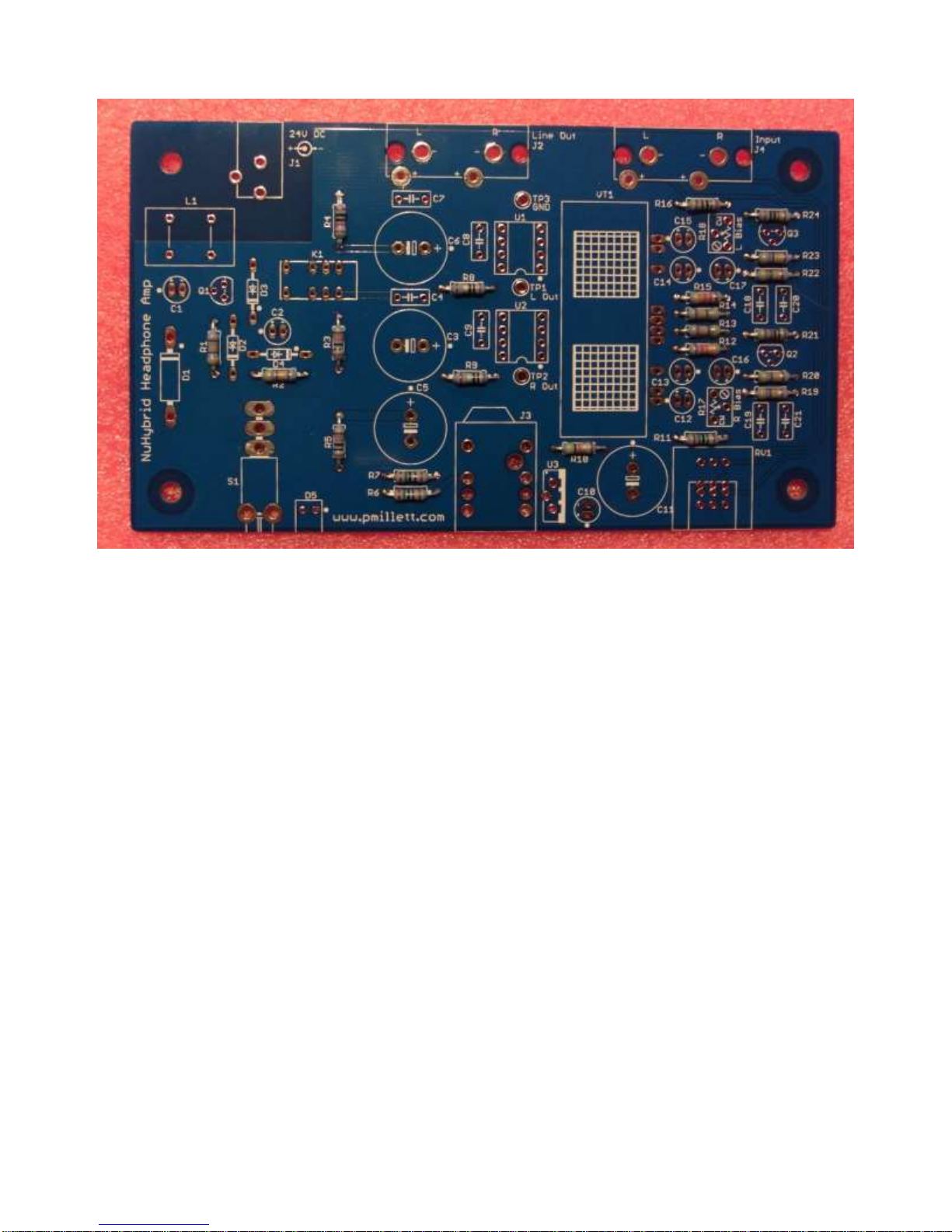
"NuHybrid" Solid-State Headphone Amplifier
Assembly instructions
What you need:
The bare PCB plus Korg Nutube 6P1 (from pmillett.com via eBay)
The parts (from Mouser)
A soldering iron and solder (Tin/Lead 63/37 is the easiest to work with - lead-free
solder is more difficult)
Wire cutters ("diagonal cutters")
DMM (Digital Multimeter)
The following are optional, but recommended:
Needle-nose pliers
To order the parts from Mouser, go to
http://www.mouser.com/ProjectManager/ProjectDetail.aspx?AccessID=b68a30231c, or go to the
"Tools" page at http://www.mouser.com/Tools/Tools.aspx and enter this access code in "Cart
Sharing" towards the bottom of the page: b68a30231c
The Mouser BOM includes all of the parts needed to build the NuHybrid except for the PCB
and the Korg Nutube, which are available from http://stores.ebay.com/pmillett. You can also
refer to the bill of materials at the end of this document for additional info.
Occasionally one of the parts on the BOM may be out of stock. The BOM has some
suggestions for alternate parts that can be used instead, as well as alternate parts that are
available from Digi-Key. Note that the Mouser BOM may be updated from time to time as
parts become difficult to source.
When assembling, keep the BOM and schematic handy, in case you have any questions
about what parts go where.
It is assumed that the builder has some basic electronics knowledge, like knowing which end
of the soldering iron to hold in the hand, and hopefully some experience building electronics.
However, this is a very easy project and is suitable for a first-time builder.
If you are new to soldering, it's highly recommended that you review one or more of the
excellent on-line soldering tutorials. Just search "soldering tutorial" on the web and/or
YouTube.
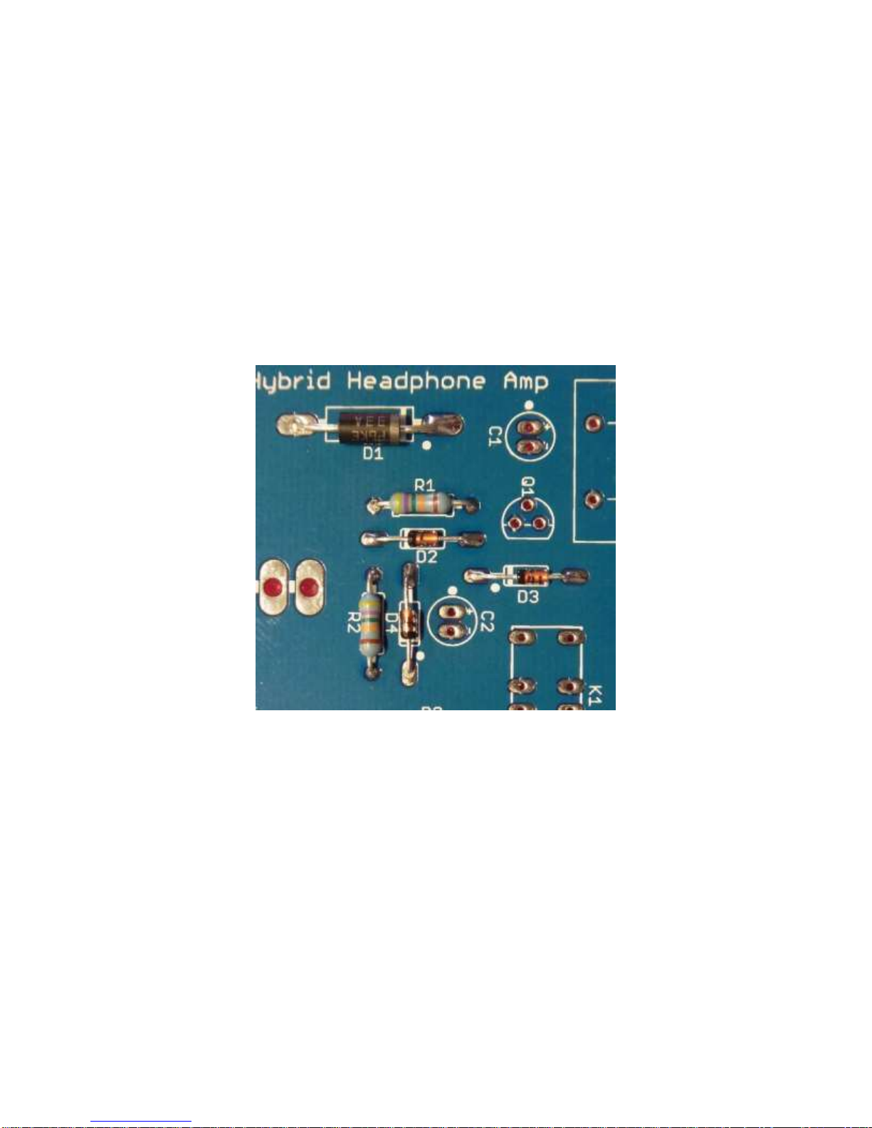
There is nothing sacred about the order that is listed for assembly. It can be convenient to
build starting with low-profile components, and work your way up to taller parts, so it's easier
to solder on the board backside. That is the way the instructions read. But you can install
parts in any order you want.

PCB Assembly
Step 1. Introduction
Start with familiarizing yourself with the bare PC board:
You'll see that each part has an outline silkscreened on the board, and a reference
designator (name) next to it. Parts are numbered starting at the lower left, so you can expect
to find resistor R1 somewhere near the lower left corner.
Some parts, like resistors, have no polarity and can be installed in either orientation. Others,
like diodes and electrolytic capacitors, need to be installed in a particular direction. These
parts have the orientation clearly marked on the silkscreen with a dot for the positive terminal
for capacitors, and a bar and dot for the cathode side of diodes.

2. Install resistors
Each bag of parts from Mouser looks like this:
Match the Mouser part number or the description with the parts on the BOM. In this case,
you will see that 33.2k resistors are installed at R12 and R15.

Note that the resistors may be different colors.
In no particular order, install the resistors. After you remove them from the bag, you'll need to
bend the leads (you can just use your fingers) so they look like this:
Next, insert them into the PCB in the appropriate spots:
Push them down flush with the board:

And bend the leads on the backside slightly:
Next, solder the leads. Touch the soldering iron tip to both the pad and the lead, and apply a
little solder:


Next, using wire cutters ("diagonal cutters"), trim the excess wire leads:
It should wind up looking like this:
Now, repeat this process for all of the resistors.

When you’re done, the board should look like this:

2. Install diodes
The diodes are installed the same way as the resistors.
Diodes need to be installed in the correct orientation, so be careful and double-check to make
sure they are pointed the right way before soldering.
Note the diodes have a band on one end that matches with the band on the PCB silkscreen,
and the PCB also has a dot near that end.
Be careful, as the two 1N4148 diodes (D3 and D4) look virtually identical to the 1N5245B
Zener diode (D2)!
As with the resistors, bend the leads and solder, then trim the excess lead wires.
Check again that they are in the right way by matching them to this photo:

3. Install IC sockets
Two IC sockets are installed for the opamps, so you can change them to different ones if
desired. Note the orientation of the sockets - there is a small notch to indicate pin 1, which is
aligned with the PCB silkscreen:

The IC sockets are soldered in as before, but since they have short pins that cannot be bent,
they somehow need to be held in place while you solder the pins. If you are dexterous you
can hold them with one finger while soldering, or just use a piece of tape:

Flip the board over and solder the pins as before. No trimming is needed.
It should look like this when you're done:
By the way, don't worry about the flux that gets splattered on the board when soldering. It's
harmless...

4. Install film capacitors
Next, install the film capacitors. (Note that the parts provided might be slightly different sizes
or colors than those shown). These are small parts with the two lead wires sticking out one
side, so you don't have to bend the leads before inserting them into the PCB:
Bend the leads over a bit to hold them in the board, solder, and trim the excess.

5. Install the small electrolytic capacitors
Install the smaller electrolytic capacitors. Be VERY careful that they are installed the correct
way - the PCB has a dot marking the positive terminal of the capacitors. The longer lead wire
is the positive terminal. Note that on the capacitor body, only the negative side is labeled –
so the other side is positive. Insert them, bend the leads, solder and trim as before. Check
again that the orientation is correct:

6. Install large electrolytic capacitors
Install the four larger electrolytic capacitors, the same way as the smaller:

7. Install the bias adjust trim pots, transistors and voltage regulator
Install the bias adjust pots (R17 & R18), three small transistors (Q1, Q2, and Q3) and a
voltage regulator IC (U3). Note that Q1 is a 2N7000 MOSFET, and Q2 & Q3 are 2N3904
NPN transistors –they look almost the same, but you can read the part number on the
device. You need to slightly bend the leads of the transistors and voltage regulator then push
them into the PCB. Bend the leads slightly on the back, solder, and trim the leads.
(Note that Q1 isn’t visible in this photo – it is off to the left).

8. Install the test points
There are three small test points installed near the opamps. Insert them and solder.

9. Install the relay K1 and common mode inductor L1
Just place them –the relay will only go in one way, and the inductor works either direction –
bend the leads a bit, solder, and trim the excess leads.
Note that the relay may be a different color…

10. Install volume control RV1, headphone jack J3, and switch S1
These parts are simply inserted into the PCB and soldered. Some may snap into the PCB
and stay put, and some you may need to use tape or your fingers to hold it in place while you
solder them in:
Make sure you have the parts seated all the way down on the PCB before fully soldering
them in. It's best to solder only one lead, then inspect the part to see if it is fully seated on
the PCB. If not, heat the solder joint while pushing the part into the PCB.

11. Install power jack J1, input jack J4, and line out jack J2
Install the jacks on the rear edge of the PCB. J2 and J4 snap into the PCB, but J1 may need
to be held in with tape (or your fingers) when you solder it in.
As before, make sure the parts are fully seated on the PCB before completely soldering them
in!
12. Install the "power on" LED D5
The LED is installed like the small capacitors. Just make sure it's pointed off the edge of the
PCB!
Table of contents