Milli RUSH 432 Quick start guide

MILLI
RUSH 432, 632, 832
Disclaimer: Products in this specification manual must by regulation be installed by licensed and registered
trade people. The manufacturer/distributor reserves the right to vary specifications or delete models from
their range without prior notification. Dimensions and set-outs listed are correct at time of publication
however the manufacturer/distributor takes no responsibility for printing errors.
Tech Page Version 3.3
CLEANING RECOMMENDATIONS
This bathroom product should not be cleaned with abrasive materials eg. steel wool/scourers. Do not use any corrosive or
abrasive cleaning agents containing acids or scouring agents. Do not use organic solvents (terps, meths, thinners) to clean
matte black and white coated towel rails. Bleaches can also discolour products and therefore should not be used.
Use a soft cloth moistened with warm soapy water or a silicone based household wax/polish such as SC Johnson ‘Pledge’
for general polishing and cleaning of the appliance. Fine scratching can be removed using the correct metal polish.
Recommended brands are ‘Autosol’ and ‘Brasso Paste’, both available in tubes from supermarkets and car care outlets.
Damage caused by any improper treatment is not covered by the product warranty- refer to Warranty Conditions on the last
page.
To see the complete Kado range go to
www.reece.com.au/bathrooms
SPECIFICATIONS
Recommeded use Residential and Commercial
Materials Stainless steel 304 grade
Finish Mirror polish, Matte Black
Technology Dry element (no leaks)
Element Replaceable
Options Heated or Non heated
Power entry ANY leg, left or right
Voltage 12V AC safety isolating transformer
Wattage 432 - 17W, 632 - 17W, 832 - 19W
Standards AS/NZS:60335.2.43
Safety rating IPX7 (immersion at 1 metre for 30mins )
FEATURES
Low Voltage Safe installation in ANY zone
Easy install ALL wall types, pre-wiring IS required
Any leg cable Cable can enter left or right
Ecotimer Ecotimer included (*with transformer kit-not incl)
360
500
432
70
250 Ty p
500
560
70
632
250 Ty p
250 Ty p
70
832
500
760
Table 1.0
page 1 of 4
Please note: Each individual rail is sold separately.

MILLI
RUSH 432, 632, 832
Electricians, please ensure a copy of the installation
instructions is left with the end user for future reference
INSTALLATION INSTRUCTIONS
SAFETY
This appliance is not intended for use by persons (including children) with
reduced physical, sensory or mental capabilities, or lack of experience and
knowledge, unless they have been given supervision or instruction concerning
use of the appliance by a person responsible for their safety. Children should
be supervised to ensure that they do not play with the appliance.
WARNING: In order to avoid a hazard for very young children, this appliance
should be installed so that the lowest heated rail is at least 600 mm above the
floor.
ELECTRICAL
• Must be installed by a registered electrician.
• The 12V ‘safety isolating’ transformer supplied must be located in a
dry accessable location (do not cover with insulation).
• Distance from transformer to towel rail must be less than 2 metres.
see *FAQ’s
• Typical locations include:
- ceiling cavity
- wall cavity (behind switch plate)
- cupboard
• Means for disconnection must be incorporated in the xed wiring in
accordance with wiring guidlines AS/NZS 3000:2000.
• The waterproof wirenut connectors provide an IPX7 rating
• The towel rail may be installed in wet area electrical zones 1, 2 & 3 as
specied in AS/NZS 3000:2000.
• Manufactured and tested to AS/NZS 60335.2.43
• Minimum 50 mm clearance to surrounding surfaces.
1. WALL PREPARATION
• ‘Rush’ heated towel rails may be xed to ANY type of wall, timber stud, steel
stud or masonry (solid or cavity).
• Stud walls (timber or steel) require timber nogs at the correct position for all
legs. See table 1.0 for xing dimensions.
• If the precise position can’t be determined early in the job, consider nogging
with 18mm construction ply, covering a larger area.
• Be aware that attempting to x into plasterboard or cement sheeting alone
is NOT recommended. Plasterboard (in particular) will not hold long term.
2. PRE WIRING
• First determine which side (left or right) you would like the cable to enter the
heated towel rail.
• In general, the leg that is closest to the transformer and farthest from wet
areas. eg. top left leg if the transformer is in the ceiling and shower is to the
right.
• For stud walls drill a 10mm hole in the noggin for the low voltage wiring
supplied at the leg position chosen. Typical layout see Fig 1.0 Table 1.0 for
xing dimensions.
Fig 1.0
Fig 3.0
Fixed wiring
Transformer
12V wiring
Studs
Nogs
4” GRINDER
Fig 2.0
Black polytube
wedged in slot
Appliance wire
supplied
page 2 of 4

MILLI
RUSH 432, 632, 832
Electricians, please ensure a copy of the installation
instructions is left with the end user for future reference
2. PRE WIRING - CONTINUED.
• For masonry walls using an angle grinder and masonry cutting disc,
cut a 25mm deep slot from the cable leg to the eventual location of the
transformer, see Fig 2.0
• Place the supplied low voltage wiring in the slot created and render over
directly.
• Black poly tube is supplied to locate the wire in the correct position, typically
250mm centres.
• Conduit may also be used but is not essential.
• Low voltage wiring tails should protrude from the nished lined wall approx
150mm to allow for trimming.
3. TOWEL RAIL CONNECTION
• Disconnect either the left or right hand wirenut. This will depend on which
side you want the wiring connection to be made in, decided in step 1.
• If a wirenut is accidentally removed, it may be reconnected with the spare
waterproof wirenut connector provided. Waterproof wirenuts MUST NOT BE
REUSED.
• Fix the polycarbonate bushes to the wall using the screws provided. DO
NOT substitute other screws. In particular, DO NOT use countersunk head
screws less than 50mm long.
• Use the towel rail as a guide to determine the correct position for the bushes
or use the xing dimensions Table 1.0. MAKE SURE IT IS LEVEL.
• Make the electrical connection to the towel rail using the waterproof wirenut
connectors provided. See Fig 7.0
• The connectors and excess wiring should be pushed back into the leg of
the towel rail.
• If there is a concern that water may enter into the wall cavity, neutral cure
silicone sealant may be applied around the cable where it exits the wall
lining.
• Finally, x the towel rail in position using the small stainless steel screws
provided. See Fig 5.0
• Note: Drilling a 2mm pilot hole makes it much easier to screw in the
self tapping screws. The bushes are moulded from glass reinforced
polycarbonate and are very hard.
4. TIMER AND SWITCH
• The towel rail must have a switch in the bathroom that can be identied
as the towel rail switch. This is typically a separate switch mechanism on
the light switch plate for the bathroom. eg. 3 gang switch plate - lights -
extractor - towel rail
• The supplied ‘ECOTIMER’ is a 230 - 240V device that should be installed
behind the switchplate between the switch and the transformer. See g 6.0
To wel Rail
Wall Switch
Transformer
N
L
Mains
12 Volt
Ecotimer
Red
Blue
Brown
To wel Rail
To wel Rail
Fig 4.0
Fig 5.0
Fig 6.0
Remove wirenut from
ONE side only
25mm
page 3 of 4

MILLI
RUSH 432, 632, 832
Electricians, please ensure a copy of the installation
instructions is left with the end user for future reference
COMPONENT LIST
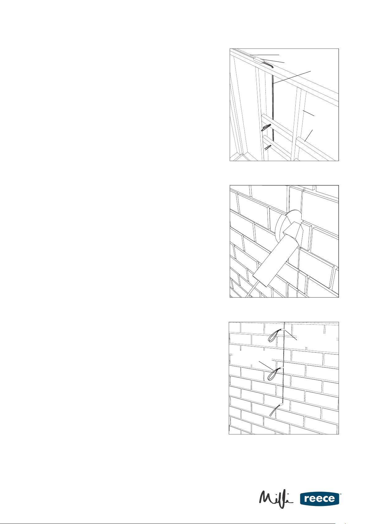
1 x Black polytube 40mm
4 x Black polytube 5mm, to hold wire in masonry slot
3 x Waterproof wirenuts
2 x Large zinc plated self tapping screws, pan head 10g x 50mm
2 x Stainless steel grub screws, 4g x 1/4” countersunk head
2 x Plastic rawl plugs, for installation on masonry walls
2 x Black rectangular polycarbonate bushes
CORRECT USE OF WATERPROOF WIRENUTS
• Strip wires 12.7mm (1/2”).
• Align any frayed strands or conductors.
• Pre-twisting unnecessary. Place stripped wires together with ends of
insulation even.
• Twist connector onto wires pushing rmly until hand tight. Do not over
torque.
• Wipe sealant in and around conductors and connector opening while
tightening. DO NOT REUSE
FAQ’s
Q. Can I place the towel rail more than 2 metres from the transformer?
A. The main reason for the limit is NOT voltage drop, as this may be overcome with larger wire. Modern electronic transformers
operate at very high frequencies and extending the length of low voltage wiring will cause unacceptable levels of radio
frequency interference (buzzing on AM radios). This may not just affect your own home, but potentiallly neighbours as well,
and should be taken seriously. Old technology ‘iron core’ transformers do not have this problem and may be used to extend
longer than 2 metres, provided that larger cable is used to counteract voltage drop. Electricians may contact DC Short Ltd for
further technical advice if needed.
Q. Is my towel rail operating at the correct temperature?
A. Towel rails will not feel as hot on cold winter days as they do on hot summer days as they are not thermostatically controlled.
The towel rail contains no moving parts or electrical contacts, this ensures a long life.
A quick test to determine if the rail is functioning correctly follows:
1. Turn the towel rail on and leave for one hour with no towels.
2. After one hour each bar of the towel rail should be a similar temperature, but no more than warm.
3. Cover each bar of the towel rail with a DRY FOLDED towel, three towels (a double layer of towelling on each bar). Leave
the towel rail on for another hour.
4. After one hour check that the temperature underneath the towelling on each bar is HOT to the touch. The exposed
surfaces should remain warm only.
Q. I have tested the transformer with a multimeter prior to installation and detect no voltage?
A. Electronic transformers operate at high frequencies, above the sampling frequency of a standard multimeter. It is unlikely
that a multimeter will detect any voltage. It should also be noted that electronic transformers will not start without a load
connected. If you need to test that the transformer is functioning correctly, EITHER connect the transformer to the towel rail to
see if it gets warm, OR temporarily connect a 50W halogen lamp to the transformer to see if it lights up.
TRANSFORMER KIT (*TO BE ORDERED SEPARATELY)
1 x Ecotimer
1 x Electronic transformer
2 x 3m lengths 1mm2 appliance wire 90 deg C
Fig 7.0
page 4 of 4
This manual suits for next models
2
Table of contents
Other Milli Bathroom Fixture manuals
Popular Bathroom Fixture manuals by other brands

Hans Grohe
Hans Grohe Vernis Blend 71420 Series Assembly instructions

noken
noken Seasons 100278599 manual

Cornat
Cornat NOIR TECBE3302 Instruction-manual / Warranty terms

Hans Grohe
Hans Grohe PuraVida 15777 Series Instructions for use/assembly instructions

DURAVIT
DURAVIT N1 4280 Mounting instructions

Anzzi
Anzzi EDAN SP-AZ024 install guide

MX
MX Neptune Showers Solo installation instructions

Hans Grohe
Hans Grohe Croma 100 27105000 Assembly instructions

Artos
Artos PS140 installation guide

agape
agape RIGO maintenance

Hans Grohe
Hans Grohe Raindance Showerpipe 27235000 Instructions for use/assembly instructions

Kohler
Kohler C3-149/K-18649T-HC-0 installation guide