manuals.online logo
Brands
  1. Home
  2. •
  3. Brands
  4. •
  5. Milnor
  6. •
  7. Washer
  8. •
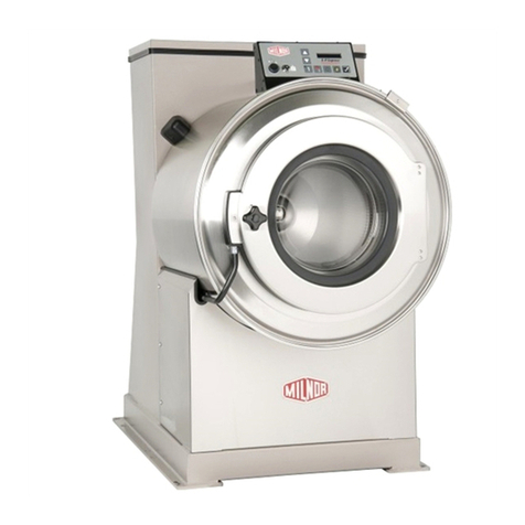
  9. Milnor MWR12J5 User manual

Milnor MWR12J5 User manual

This manual suits for next models

9

Other Milnor Washer manuals

Milnor 76028 G3 CBW Manual

Milnor

Milnor 76028 G3 CBW Manual

Milnor 42030V Series User manual

Milnor

Milnor 42030V Series User manual

Milnor 30015V7J User manual

Milnor

Milnor 30015V7J User manual

Milnor 36026X8R User manual

Milnor

Milnor 36026X8R User manual

Milnor MWF100C7 User manual

Milnor

Milnor MWF100C7 User manual

Milnor 30022F Series Assembly instructions

Milnor

Milnor 30022F Series Assembly instructions

Milnor MWR/T12X5 User manual

Milnor

Milnor MWR/T12X5 User manual

Milnor Mark II User manual

Milnor

Milnor Mark II User manual

Milnor 30015C4A User manual

Milnor

Milnor 30015C4A User manual

Milnor EX-15 ES Installation and operation manual

Milnor

Milnor EX-15 ES Installation and operation manual

Milnor 36030F Series User manual

Milnor

Milnor 36030F Series User manual

Milnor 30022Fxx User manual

Milnor

Milnor 30022Fxx User manual

Milnor 36026V5J, 36026V7J Assembly instructions

Milnor

Milnor 36026V5J, 36026V7J Assembly instructions

Milnor MCT27E5 Manual

Milnor

Milnor MCT27E5 Manual

Milnor 42 Series Operating manual

Milnor

Milnor 42 Series Operating manual

Milnor 30022H7J Installation and operating manual

Milnor

Milnor 30022H7J Installation and operating manual

Milnor MWF C Series Installation and operating manual

Milnor

Milnor MWF C Series Installation and operating manual

Milnor Mark II Instruction Manual

Milnor

Milnor Mark II Instruction Manual

Milnor 36021V5Z Assembly instructions

Milnor

Milnor 36021V5Z Assembly instructions

Milnor Q4J Series User manual

Milnor

Milnor Q4J Series User manual

Milnor 48040F7D Manual

Milnor

Milnor 48040F7D Manual

Milnor 30022H7x Assembly instructions

Milnor

Milnor 30022H7x Assembly instructions

Milnor 36 Series Operating manual

Milnor

Milnor 36 Series Operating manual

Milnor MWF63C7 Manual

Milnor

Milnor MWF63C7 Manual

Popular Washer manuals by other brands

Zanussi ZWF 14080 W user manual

Zanussi

Zanussi ZWF 14080 W user manual

Zanussi FV 825 N Instruction booklet

Zanussi

Zanussi FV 825 N Instruction booklet

LG WM8000HVA Specifications

LG

LG WM8000HVA Specifications

Whirlpool 3RGSC9400 Use and care guide

Whirlpool

Whirlpool 3RGSC9400 Use and care guide

Zanussi TJ 1284 H instruction manual

Zanussi

Zanussi TJ 1284 H instruction manual

AEG KO-LAVAMAT 74740 User information

AEG

AEG KO-LAVAMAT 74740 User information

Beko WSRE7512PRA user manual

Beko

Beko WSRE7512PRA user manual

Whirlpool LA5OOOXP Use and care guide

Whirlpool

Whirlpool LA5OOOXP Use and care guide

Miele PW 6207 operating instructions

Miele

Miele PW 6207 operating instructions

GE GE Profile WWSE3160AAA Specifications

GE

GE GE Profile WWSE3160AAA Specifications

Bush WMNB712EB instruction manual

Bush

Bush WMNB712EB instruction manual

ALLIANCE UW60AV Information manual

ALLIANCE

ALLIANCE UW60AV Information manual

Bosch WAN280H3 User manual and installation instructions

Bosch

Bosch WAN280H3 User manual and installation instructions

Maytag MAT15MNAW installation instructions

Maytag

Maytag MAT15MNAW installation instructions

LG T2109VSAL owner's manual

LG

LG T2109VSAL owner's manual

Indesit IWC 61481 Instructions for use

Indesit

Indesit IWC 61481 Instructions for use

Electrolux EWF12843 user manual

Electrolux

Electrolux EWF12843 user manual

Indesit WIN 70 Instructions for use

Indesit

Indesit WIN 70 Instructions for use

manuals.online logo
manuals.online logoBrands
  • About & Mission
  • Contact us
  • Privacy Policy
  • Terms and Conditions

Copyright 2025 Manuals.Online. All Rights Reserved.

Published Manual Number/ECN: ME7MJR11AE/2021046A
• Publishing System: TPAS2
• Access date: 01/22/2021
• Document ECNs: Latest
Schematic/Electrical Parts
Milnor® Washer-Extractor
MWR/T12J5, MWR/T16J5,
MWR/T18J4,
MWR/T18J6, MWR/T27J5
PELLERIN MILNOR CORPORATION POST OFFICE BOX 400, KENNER, LOUISIANA 70063-0400, U.S.A.
Table of Contents
ME7MJR11AE/21046A
Page Description Document
1 Component Parts List W7MJRPL/2021046N
3 Limited Standard Warranty BMP720097/2019036
4 How to Get the Necessary Repair Components BIUUUD19/20081231
5 How to Use Milnor® Electrical Schematic Diagrams BIUUUK01/20130308
18 Sample Schematic BMP010012/2018343
20 3 Phase Motor Connection Diagram BMP850029/1999362B
21 3P Motor Diagram-Multivolt W80008/2001253A
22 Board to Board Wiring W7MJRBW/2012462B
24 Flushing Supplies W7MJRCF/2007354B
26 Electrical Valves W7MJREV/2007354B
28 Microprocessor Inputs W7MJRIA/2014303B
30 Control Circuit Transformer W7MJRLV/2017365B
32 Start Circuit W7MJRS+/2013103B
34 Variable Speed Controller W7MJRVPA/2020424B
C O M P O N E N T P A R T S L I S T W7MJRPL/20210456N
COMPONENT FUNCTION OF THIS WHERE TO FIND
NUMBER COMPONENT NUMBER THIS COMPONENT MILNOR P/N DESCRIPTION LOCATION
>>>CONTROL BOX LAYOUTS
BA >>PRINTED CIRCUIT BOARDS
BADV BOARD=DISPLAY/SWITCH PANEL W7MJRBW 98CMCR1823 BD:EP PLUS DISPLAY BEHIND SWPNL
BAUP BOARD=PROCESSOR+I/O W7MJRBW 98CMCR1822 BD:EP PLUS ->TEST CONTROL PANEL
CR >>RELAY-PILOT OR CONTROL
CRD RELAY-OK TO OPEN DOOR W7MJRS+ 09CMCR1832 RELAY 4 POLE 240V OMRON CONTROL PANEL
CRDL RELAY-DOOR CLOSED AND LOCKED W7MJRS+ 09CMCR1832 RELAY 4 POLE 240V OMRON CONTROL PANEL
CRE RELAY-OK TO LOCK DOOR W7MJRS+ 09CMCR1832 RELAY 4 POLE 240V OMRON CONTROL PANEL
CS >>CONTACTOR-MOTOR STARTER
CSVP CONTACTOR-ENABLE INVERTER W7MJRS+ 98CMCR1801 12A 3P CONTACTOR NR 240V5/6 CONTROL PANEL
EF >>FUSE OR FUSE HOLDER
EF71A FUSE-CONTROL CIRCUIT X-BUS W7MJRS+ 09FF002F2H 2A 250V F2H CONTROL FUSE CONTROL PANEL
EF71B FUSE-CONTROL CIRCUIT Y-BUS W7MJRS+ 09FF002F2H 2A 250V F2H CONTROL FUSE CONTROL PANEL
EFP1 FUSE-HV FEED TRANSFORMER PRIMARY W7MJRLV 09FF003AWV FUSE BUSS STYLE CC TYPE FNQ-R 3 AMP 60 CONTROL PANEL
EFP2 FUSE-HV FEED TRANSFORMER PRIMARY W7MJRLV 09FF003AWV FUSE BUSS STYLE CC TYPE FNQ-R 3 AMP 60 CONTROL PANEL
EM >>ELECTROMAGNET AND SOLENOID
EMDL SOLENOID-DOOR UNLOCK W7MJRS+ 09K063C24 DOOR LOCK SOLENOID 24V DOOR LATCH
EMDR SOLENOID-DRAIN VALVE W7MJREV 96D35RAA71 DRAINVAL RT-ANG 3" 240V 50/60C BELOW SHELL
ES >>POWER SUPPLY-ELECTRONIC
ESPS POWER SUPPLY-MICROPROCESSOR W7MJRBW 98CMCR1825 PWRSP 5/12/-12V 85-264VAC/IN CONTROL PANEL
ET >>THERMAL OVER LOAD
ETVP OVERLOAD-DRIVE INVERTER LOW VOLTAGE W7MJRVPA 98MCR1829 OVERLOAD MWR18 LOW VOLT 7.5-11 CONTROL PANEL
ETVP OVERLOAD-DRIVE INVERTER HIGH VOLTAGE W7MJRVPA 98MCR1830 OVERLOAD MWR18 HIGH VOLT 3.5-5 CONTROL PANEL
EX >>TRANSFORMERS
EXHV TRANSFORMER-INCOMING VOLT.240VAC W7MJRLV MESSAGE EW SEE EX37-1 OR -2 FOR VOLTAGE CONTROL PANEL
EXHV-1 TRANSFORMER-208VAC TO 240VAC W7MJRLV 98CMCR0902 AUTOXFMR 208V/230V 250VA CONTROL PANEL
EXHV-3 TRANSFORMER-380/480V TO 240V W7MJRLV 09UA025AAB XFMR 380-480PRI/120-240SEC250V CONTROL PANEL
H>>HEATING COIL
H COIL-HEATER W7MJRVPA 98CMCR4206 HEATING ELEMENT 5KW (0090-2318) BELOW SHELL
MT >>MOTORS
MTWE MOTOR-WASHER W7MJRVPA MESSAGE SO SEE SPECIFIC COMPONENT+NAMEPLATE BELOW SHELL
MV >>>MOTOR POWER INVERTERS
MVINV INVERTER-VARI SPEED LOW VOLTAGE W7MJRVPA 09MV030F74 VARSPEED 3HP 11A 230V GPD315 CONTROL PANEL
Page 1 of 2
1
C O M P O N E N T P A R T S L I S T W7MJRPL/20210456N
COMPONENT FUNCTION OF THIS WHERE TO FIND
NUMBER COMPONENT NUMBER THIS COMPONENT MILNOR P/N DESCRIPTION LOCATION
SH >>SWITCH-HAND OPERATED
SH01 SWITCH-208/240VAC W7MJRLV 09N050 TOGSW SPDT NO OFF 10A250V CONTROL PANEL
SHDO SWITCH-UNLATCH DOOR W7MJRS+ 09N405PB10 SWASS PBBK 1NO DOOR LATCH
SHDO SWITCH-UNLATCH DOOR W7MJRIA 09N401CBNO CONT BLOCK 1-NO #ZBE101 DOOR LATCH
SHMF SWITCH-MANUAL FLUSH W7MJRCF MESSAGE MS CHEMICAL FLUSHING VALVE BY OTHERS SUPPLY INJECT
SK >>SWITCH-KEYLOCK
SKPR SWITCH-RUN/PROGRAM W7MJRIA 09N127C KEYSW SPST 7A120VAC SCREW TERM SWITCH PANEL
SM >>SWITCH-MECHANICAL OPERATED
SMD SWITCH-DOOR CLOSED W7MJRS+ 02-04177 MICROSWITCH, 1 IN LEVER DOOR LATCH
SME SWITCH-DOOR IS LOCKED W7MJRS+ 09R010D DOOR LOCK SWITCH DOOR LATCH
SMWVB SWITCH-VIBRATION W7MJRIA 98CMCR0910 VIBRATION SWITCH CONTROL PANEL
SP >>>SWITCH-PRESSURE
SPHL PRESSURE SW.-HIGH WATER LEVEL W7MJRIA 09N086A PRESS SWITCH EATON #738-761 CONTROL PANEL
SPLL PRESSURE SW.-LOW WATER LEVEL W7MJRIA 09N086A PRESS SWITCH EATON #738-761 CONTROL PANEL
TP >>>TEMPERATURE PROBE
TP PROBE-TEMPERATURE W7MJRBW 98CMCR3605 ELECTRIC HEATER PROBE CONTROL PANEL
VE >>VALVE-ELECTRIC OPERATED
VEC1 VALVE-FLUSH DETERGENT W7MJRCF MESSAGE MS CHEMICAL FLUSHING VALVE BY OTHERS SUPPLY INJECT
VEC2 VALVE-FLUSH BLEACH W7MJRCF MESSAGE MS CHEMICAL FLUSHING VALVE BY OTHERS SUPPLY INJECT
VEC3 VALVE-FLUSH SOUR W7MJRCF MESSAGE MS CHEMICAL FLUSHING VALVE BY OTHERS SUPPLY INJECT
VEC4 VALVE-FLUSH SOFTNER W7MJRCF MESSAGE MS CHEMICAL FLUSHING VALVE BY OTHERS SUPPLY INJECT
VEC5 VALVE-FLUSH STARCH W7MJRCF MESSAGE MS CHEMICAL FLUSHING VALVE BY OTHERS SUPPLY INJECT
VEFL VALVE-FLUSH W7MJREV 98CMCR0938 3/4 INLET 13M 3 OUT 220/240V REAR OF MACH
VEMF VALVE-MANUAL FLUSH W7MJRCF MESSAGE MS CHEMICAL FLUSHING VALVE BY OTHERS SUPPLY INJECT
VEWC VALVE-COLD WATER W7MJREV 98CMCR0937 3/4"DUOINLET 1/2"HOSEOUT REAR OF MACH
VEWH VALVE-HOT WATER W7MJREV 98CMCR0937 3/4"DUOINLET 1/2"HOSEOUT REAR OF MACH
Page 2 of 2
2
BMP720097/19036
PELLERIN MILNOR CORPORATION
LIMITED STANDARD WARRANTY
We warrant to the original purchaser that MILNOR machines including electronic hardware/software
(hereafter referred to as “equipment”), will be free from defects in material and workmanship for a
period of one year from the date of shipment (unless the time period is specifically extended for
certain parts pursuant to a specific MILNOR published extended warranty) from our factory with no
operating hour limitation. This warranty is contingent upon the equipment being installed, operated
and serviced as specified in the operating manual supplied with the equipment, and operated under
normal conditions by competent operators.
Providing we receive written notification of a warranted defect within 30 days of its discovery, we
will—at our option—repair or replace the defective part or parts, EX Factory (labor and freight
specifically NOT included). We retain the right to require inspection of the parts claimed defective in
our factory prior to repairing or replacing same. We will not be responsible, or in any way liable, for
unauthorized repairs or service to our equipment, and this warranty shall be void if the equipment is
tampered with, modified, or abused, used for purposes not intended in the design and construction
of the machine, or is repaired or altered in any way without MILNOR's written consent.
Parts damaged by exposure to weather, to aggressive water, or to chemical attack are not covered
by this warranty. For parts which require routine replacement due to normal wear—such as gaskets,
contact points, brake and clutch linings, belts, hoses, and similar parts—the warranty time period is
90 days.
We reserve the right to make changes in the design and/or construction of our equipment (including
purchased components) without obligation to change any equipment previously supplied.
ANY SALE OR FURNISHING OF ANY EQUIPMENT BY MILNOR IS MADE ONLY UPON THE EXPRESS
UNDERSTANDING THAT MILNOR MAKES NO EXPRESSED OR IMPLIED WARRANTIES OF
MERCHANTABILITY OR FITNESS FOR ANY PARTICULAR USE OR PURPOSE OR ANY OTHER
WARRANTY IMPLIED BY LAW INCLUDING BUT NOT LIMITED TO REDHIBITION. MILNOR WILL NOT
BE RESPONSIBLE FOR ANY COSTS OR DAMAGES ACTUALLY INCURRED OR REQUIRED AS A RESULT
OF: THE FAILURE OF ANY OTHER PERSON OR ENTITY TO PERFORM ITS RESPONSIBILITIES, FIRE
OR OTHER HAZARD, ACCIDENT, IMPROPER STORAGE, MIS-USE, NEGLECT, POWER OR
ENVIRONMENTAL CONTROL MALFUNCTIONS, DAMAGE FROM LIQUIDS, OR ANY OTHER CAUSE
BEYOND THE NORMAL RANGE OF USE. REGARDLESS OF HOW CAUSED, IN NO EVENT SHALL
MILNOR BE LIABLE FOR SPECIAL, INDIRECT, PUNITIVE, LIQUIDATED, OR CONSEQUENTIAL COSTS
OR DAMAGES, OR ANY COSTS OR DAMAGES WHATSOEVER WHICH EXCEED THE PRICE PAID TO
MILNOR FOR THE EQUIPMENT IT SELLS OR FURNISHES.
THE PROVISIONS ON THIS PAGE REPRESENT THE ONLY WARRANTY FROM MILNOR AND NO OTHER
WARRANTY OR CONDITIONS, STATUTORY OR OTHERWISE, SHALL BE IMPLIED.
WE NEITHER ASSUME, NOR AUTHORIZE ANY EMPLOYEE OR OTHER PERSON TO ASSUME FOR US,
ANY OTHER RESPONSIBILITY AND/OR LIABILITY IN CONNECTION WITH THE SALE OR FURNISHING
OF OUR EQUIPMENT TO ANY BUYER.
3
How to Get the Necessary Repair Components
PELLERIN MILNOR CORPORATION
BIUUUD19 (Published) Book specs- Dates: 20081231 / 20081231 / 20081231 Lang: ENG01 Applic: UUU
How to Get the Necessary Repair Components
This document uses Simplified Technical English.
Learn more at http://www.asd-ste100.org.
You can get components to repair your machine from the approved supplier where you got this
machine. Your supplier will usually have the necessary components in stock. You can also get
components from the Milnor®factory.
Tell the supplier the machine model and serial number and this data for each necessary component:
• The component number from this manual
• The component name if known
• The necessary quantity
• The necessary transportation requirements
• If the component is an electrical component, give the schematic number if known.
• If the component is a motor or an electrical control, give the nameplate data from the used
component.
To write to the Milnor factory:
Pellerin Milnor Corporation
Post Office Box 400
Kenner, LA 70063-0400
UNITED STATES
Telephone: 504-467-2787
Fax: 504-469-9777
Email: [email protected]
— End of BIUUUD19 —
4
How to Use Milnor®Electrical Schematic Diagrams
PELLERIN MILNOR CORPORATION
BIUUUK01 (Published) Book specs- Dates: 20130308 / 20130308 / 20130308 Lang: ENG01 Applic: PCR UUU
How to Use Milnor®Electrical Schematic Diagrams
Milnor®electrical schematic manuals contain a table of contents/component list and a set of
schematic drawings. These documents are cross referenced and must be used together.
The table of contents/components list shows, for every component on every schematic in the
manual, the component item number (explained in detail below), statement of function, parent
schematic number, part number, description and electric box location. In older manuals, two
component lists are provided: List 1 sorts the components by function, and List 2 by type of
component. Newer schematic manuals include only the list sorted by component number.
The schematic drawings use symbols for each electromechanical component, and indicate the
function of each. Integrated circuits are not shown, but the function of each microprocessor input
and output is stated. Certain electrical components not pertinent to circuit logic, such as wire
connectors, are not represented on the schematic.
Most machines require several schematics to describe the complete control system and all the
options available on the included models. In most manuals there are some schematic pages that
don't apply to your specific machine because certain options and configurations are mutually
exclusive or are not necessary in all markets. You may find it helpful to mark or remove such
pages. A schematic page that only applies to a subset of machines will normally state, in the title,
which models and/or options it covers. Compare this with the nameplate on your machine and
with your purchase records.
Each schematic is devoted to circuits with common functions (e.g., microprocessor inputs, motor
contactors). Schematics appear in the manual in alphanumeric order.
1. Component Prefix Classifications and Descriptions
Component item numbers consist of up to six characters and appear as part of a component's
symbol on the schematic. The first two characters indicate the general class of component, and
the remaining characters are a mnemonic for the function. For example, “CD” is the code for all
time delay relays, and “SR” stands for safety reset. Thus, CDSR is a time delay relay that serves
as a safety reset.
The following are descriptions of electrical components used in Milnor®machines. Descriptions
are in alphabetical order by the component class code (two character prefix).
Note 1: Some component class codes do not have a corresponding symbol, but are represented by a box
and an accompanying note describing the component. Examples of such codes are BA (printed circuit
board), ED (electronic display), and ES (electronic power supply).
BA=Printed Circuit Board—Insulating substrate on which a thin pattern of copper conductors
has been formed to connect discrete electronic components also mounted on the board.
CB=Circuit Breaker (Figure 1)—Automatic switch that opens an electric circuit in abnormal
current conditions (e.g., an overload).
Figure 1: Circuit Breaker (CB)
CD=Control, Time Delay Relay (Figure 2)—A relay whose contacts switch only after a fixed
or adjustable delay, once voltage has been applied to its coil. The contacts switch back to
normal (de-energized state) immediately when the voltage is removed.
5
How to Use Milnor®Electrical Schematic Diagrams
PELLERIN MILNOR CORPORATION
Figure 2: Time Delay Relay (CD)
Coil and Contacts Legend
.
A. Coil
B. Contacts
CL=Control, Latch Relay (Figure 3)—A relay which latches in an energized or set position
when operated by one coil (the latch/set coil). The relay stays latched even though coil voltage
is removed. The relay releases or unlatches when voltage is applied to a second coil (the
unlatch/reset coil).
Figure 3: Latch Relay (CL)
Coils and Contacts Legend
.
A. Coils
B. Contacts
CR=Control, Relay (Figure 4)—A relay whose contacts switch immediately when voltage is
applied to its coil and revert to normal when the voltage is removed.
Figure 4: Standard Relay (CR)
Coils and Contacts Legend
.
A. Coil
B. Contacts
CP=Control, Photo-Eye (Figure 5)—Photo-eyes sense the presence of an object without direct
physical contact. Photo-eyes consist of a transmitter, receiver, and output module. These
components may be housed in one assembly with the transmitter bouncing light off of a
reflector to the receiver, or these components can be housed in two separate assemblies with
the transmitter pointed directly at the receiver. The photo-eye can be set to turn on its output
either when the light beam becomes blocked (dark operate) or when it becomes un-blocked
(light operate).
6