Milpower Source MILTECH-9012C/G User manual

MILTECH-9012C/G USER MANUAL
Version 1.10
User’s Manual Version 1.00
1
MILTECH-9012C/G
Compact Military-Grade Managed 12-Port Gigabit Ethernet
Router/Switch with internal Computer that runs Cisco
Router
User Manual

MILTECH-9012C/G USER MANUAL
Version 1.10
User’s Manual Version 1.00
2
FCC Statement
The MILTECH-9012C/G is Gigabit Ethernet Router/Switch with internal SBC designed and produced by Milpower
Source., for use in harsh military environments.
The MILTECH-9012C/G is composed of 2 independent units, a fully managed switch with 12 triple speed
(10/100/1000) BaseT Ethernet ports, one RS-232 serial management port and a computer running Linux. Its
rugged design is intended to operate in severe environments without the need for forced air cooling.
This document is intended to provide the information required to interface with the unit (MILTECH-9012C/G)
hardware.
CE Declaration of conformity
This equipment complies with the requirements relating to electromagnetic compatibility, CE102, RE102, CS101,
SC114, CS115, CS116, RS103, ESD.
Trademarks
All Milpower Source, brand, and product names are trademarks or registered trademarks of Milpower Source.

MILTECH-9012C/G USER MANUAL
Version 1.10
User’s Manual Version 1.00
3
Preface
This user’s Manual is applied to the MILTECH-9012C/G Full Layer 3 Ethernet switch with a computer running Linux.
This document describes how to install and use the MILTECH-9012C/G, which was designed for easy installation
and high performance.
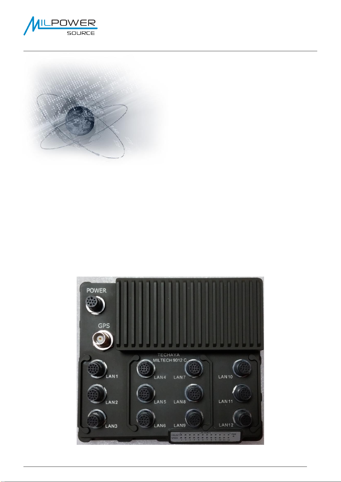
Product Overview
The MILTECH-9012C/G is specifically designed for battlefield C4ISR, voice, video, sensor data acquisition and
communications in platforms that require LAN/WAN connectivity.
While platform-internal networks need maximum speed and throughput, WAN interfaces require robust connectivity.
The MILTECH-9012C/G provides the best of both worlds in a single package - with Milpower Source’s proven line-
rate internal routing/switching AND Cisco-IOS industry-standard routing, security, and mobility protocols.
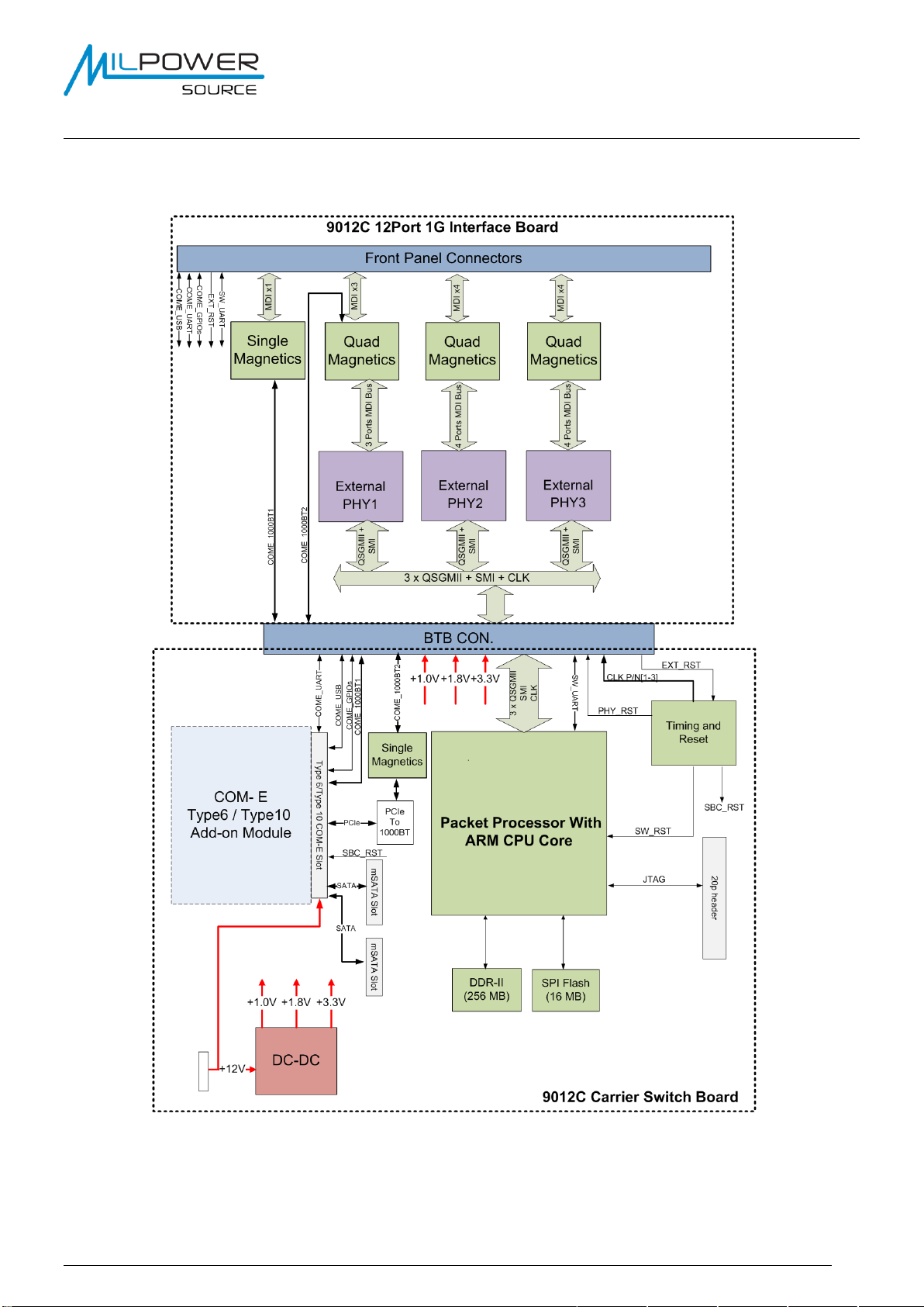
The MILTECH-9012C/G’s switch portion features both L2/L3 network switching and routing capabilities, including
virtual LANS (VLANS), traffic prioritization/QoS, IPv4/IPv6 support, and bandwidth aggregation.
The integrated Cisco ESR router transparently connects to a mobile world of wired and wireless networks, with
IPv4/IPv6 routing and multicast protocols that include BGP, OSPF, GRE, EIGRP, CDP, IGMP and MLD. Voice and
video connection quality is maintained with advanced quality of service (QoS) while external communication is
secured with the latest encryption algorithms, IPsec and IKEv2 protocols, authentication, identity management, and
integrated threat management. These advanced functions normally require a separate edge router, but are now
available in Milpower Source’s compact MILTECH-9012C/G.
The MILTECH-9012C/G offers the best combination of size, weight, and power (SWaP) in the industry, saving
valuable real estate for devices that make mobile platforms highly effective. No other military-grade device offers
such functionality in such a small package.
The 9012C is a member of the MILTECH9012 family that offers flexible alternatives for LAN, LAN/WAN, and
customizable networking. All family members are MIL-STD, fully managed, and military grade, with 12 triple-speed
(10/100/1000Mbps) ports.
The MILTECH-9012C/G gigabit-rate transmission and 24VDC power make it instantly compatible with any network
device and power systems.
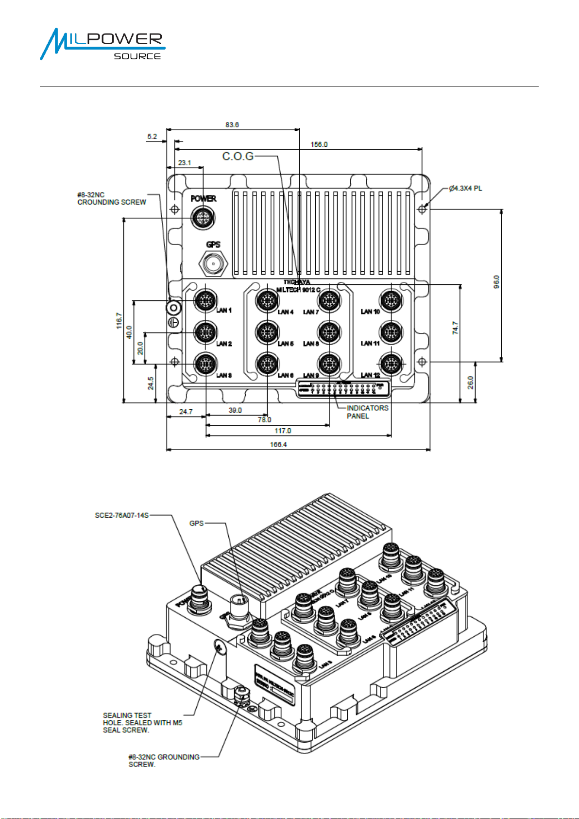
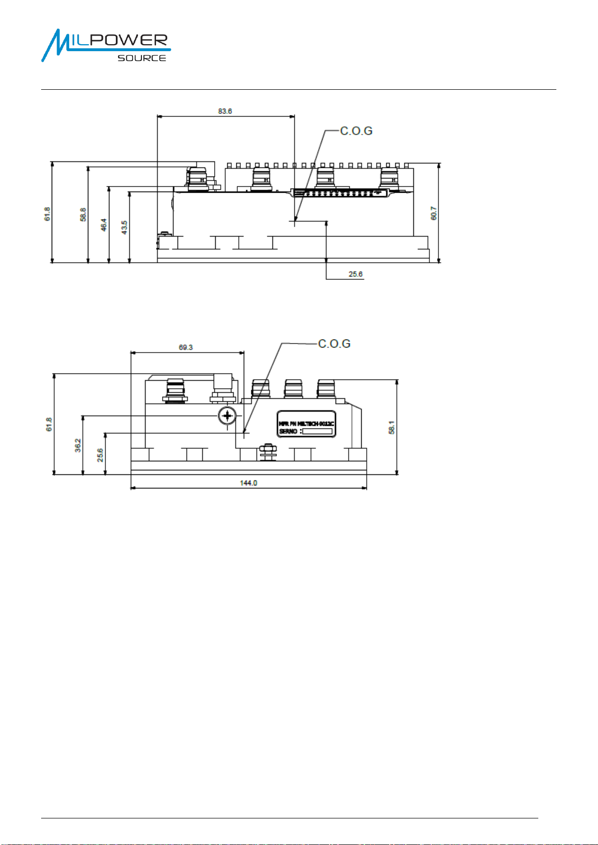
Developed for military and harsh avionic applications, the MILTECH-9012C/G’s mechanical packaging
enhancements are designed for MIL-STD-810 airborne and ground environmental compliance and high reliability.
The unit has been especially hardened to improve ingress, impact, and shock/vibration protection, as well as
eliminate all moving parts through the use of passive cooling. Sealed SCE2 Amphenol circular connectors gives
the 9012C/G an IP67 rating.
Features Overview
•12 x triple-speed (10/100/1000Mbps) managed ports
•Full Cisco IOS –5921 Router, ESR (optional)
•Both L2/L3 network switching and full routing capabilities
•Only 1.1Kg to offer the best performance and combination of size, weight, and power
•Operating at extreme temperature of -45°C to +85°C
•Meets the toughest industrial and military environments such as MIL-STD-810F, MIL-STD-461E,
Test Reports are available upon request.

MILTECH-9012C/G USER MANUAL
Version 1.10
User’s Manual Version 1.00
4
MILTECH-9012C/G HW Block Diagram

MILTECH-9012C/G USER MANUAL
Version 1.10
User’s Manual Version 1.00
5
MILTECH-9012C/G –Mechanical Dimensions

MILTECH-9012C/G USER MANUAL
Version 1.10
User’s Manual Version 1.00
6
Hardware Mounting
The MILTECH-9012C/G weighs 1.1Kg and can be mounted via four 4.5mm mounting holes on bottom for
mounting to any flat surface.
The overall external dimensions of the MILTECH-9012C/G are 166(L) x 144(W) x 68(H) millimeters, including
connectors & hardware.
Package Contents
•One MILTECH-–9012C/G Full Layer 3 Ethernet switch.
•One User’s Guide
Please inspect the contents and report any damage or missing items immediately to your authorized
reseller.

MILTECH-9012C/G USER MANUAL
Version 1.10
User’s Manual Version 1.00
7
Power Guidelines
MILTECH-9012C/G has SCE power connector (Part Number SCE2-B-76A07-10ASN-002).
The power connector contains the following electrical interfaces:
•Input power between 18-36VDC (Nominal 24VDC per MIL-STD-704A and MIL-STD-1275B) with a
maximum power consumption of 25 Watts.
•Power Mating cable connector Part Number: SCE2-B-L1K07-10APN.
GPS
MILTECH-9012C/G has TNC connector for connecting the GPS antenna. The GPS require passive
antenna connected to this port.
Ethernet and Management
MILTECH-9012C/G has 12 SCE connector (Part Number SCE2-B-76A07-14SN-001) that use as Ethernet
ports. Some ports contain additional signals as detailed in the Connectors ICD below.
•Ethernet Mating cable connector Part Number: SCE2-B-L1K07-14PN.
Ethernet Ports
The MILTECH-9012C/G Ethernet switches can be connected using Medium Dependent
Interface (MDI) or Medium Dependent Interface Crossover (MDIX) schemes.
Note: MDI is the preferred connection choice.
The following table gives wiring connections for the MILTECH-9012C/G Gigabit Ethernet ports
relative to the available link speeds.
M.9128
RJ-45
Pinout
P/N
MDI
MDI-X
1000
Base-T
100
Base-T
10
Base-T
1000
Base-T
100
Base-T
10
Base-T
Port X –A(+/-)
1/2
BI_DA+-
TX+-
TX+-
BI_D0+-
RX+-
RX+-
Port X –B(+/-)
3/6
BI_DB+-
RX+-
RX+-
BI_D1+-
TX+-
TX+-
Port X –C(+/-)
4/5
BI_DC+-
Unused
Unused
BI_D2+-
Unused
Unused
Port X –D(+/-)
7/8
BI_DD+-
Unused
Unused
BI_D3+-
Unused
Unused
Ethernet Switch Serial Port
The following table gives wiring connections for the serial management port, located on physical
port No. 1 and uses RS-232 protocol.
Signal
Direction
Type
Connects
TX
Output
RS-232
Port 1 PIN M
RX
Input
RS-232
Port 1 PIN N
GND
Reference
Ground
Port 1 PIN P

MILTECH-9012C/G USER MANUAL
Version 1.10
User’s Manual Version 1.00
8
This serial port is associated with the Switch Management Processor.
This port is RS-232 compatible and can operate at: 115,200, 8, N,1.
SBC Serial Port
The following table gives wiring connections for the serial SBC management port, located on
physical port No. 12 and uses RS-232 protocol.
Signal
Direction
Type
Connects
TX
Output
RS-232
Port 12 PIN K
RX
Input
RS-232
Port 12 PIN L
GND
Reference
Ground
Port 12 PIN P
This serial port is associated with the SBC Processor.
This port is RS-232 compatible and can operate at: 115,200, 8, N,1.

MILTECH-9012C/G USER MANUAL
Version 1.10
User’s Manual Version 1.00
9
Connectors ICD
Electrical Connections
MILTECH-9012C/G has 13 (14 in unit with GPS) connectors for both communication and power.
Port
Number
Pin
Signal
Port
Number
Pin
Signal
1
A
MDI Pair 0 +
2,
4-9
A
MDI Pair 0 +
B
MDI Pair 0 -
B
MDI Pair 0 -
C
MDI Pair 1 +
C
MDI Pair 1 +
D
MDI Pair 2 +
D
MDI Pair 2 +
E
MDI Pair 2 -
E
MDI Pair 2 -
F
MDI Pair 1 -
F
MDI Pair 1 -
G
MDI Pair 3 +
G
MDI Pair 3 +
H
MDI Pair 3 -
H
MDI Pair 3 -
J
NC
J
NC
K
NC
K
NC
L
NC
L
NC
M
RS232_TX - Ethernet Switch
M
NC
N
RS232_RX - Ethernet Switch
N
NC
P
GND - Ethernet Switch
P
NC
Port
Number
Pin
Signal
Port
Number
Pin
Signal
3
A
MDI Pair 0 +
10
A
MDI Pair 0 +
B
MDI Pair 0 -
B
MDI Pair 0 -
C
MDI Pair 1 +
C
MDI Pair 1 +
D
MDI Pair 2 +
D
MDI Pair 2 +
E
MDI Pair 2 -
E
MDI Pair 2 -
F
MDI Pair 1 -
F
MDI Pair 1 -
G
MDI Pair 3 +
G
MDI Pair 3 +
H
MDI Pair 3 -
H
MDI Pair 3 -
J
NC
J
PWR_O/G_IN
K
NC
K
GPI_0
L
GND
L
GPI_1
M
SYSTEM RESET
M
GPI_2
N
NC
N
GPI_3
P
NC
P
GND

MILTECH-9012C/G USER MANUAL
Version 1.10
User’s Manual Version 1.00
10
Port
Number
Pin
Signal
Port
Number
Pin
Signal
11
A
MDI Pair 0 +
12
A
MDI Pair 0 +
B
MDI Pair 0 -
B
MDI Pair 0 -
C
MDI Pair 1 +
C
MDI Pair 1 +
D
MDI Pair 2 +
D
MDI Pair 2 +
E
MDI Pair 2 -
E
MDI Pair 2 -
F
MDI Pair 1 -
F
MDI Pair 1 -
G
MDI Pair 3 +
G
MDI Pair 3 +
H
MDI Pair 3 -
H
MDI Pair 3 -
J
COMM_GPO
J
SBC_VBUS
K
GPO_0
K
SBC_RS232_TX
L
GPO_1
L
SBC_RS232_RX
M
GPO_2
M
SBC_USB_DP
N
GPO_3
N
SBC_USB_DN
P
GND
P
SBC_GND
Port
Pin
Signal
POWER
A
N.C
B
N.C
C
N.C
D
GND (20 AWG)
E
N.C
F
N.C
G
N.C
H
28VDC Input (20 AWG)
J
N.C
K
N.C
LED Indications
The unit has 25 LEDS indication. Each of the LAN ports has 2 LED for Speed (10/100/1000) and
Link/Activity. one green LED on the front panel labeled PWR, This LED is illuminated when input
power is applied to the MILTECH-9012C/G.
Led
Marking
Description
SPEED
Port Number
10 or 100 OFF
1000 Green
LINK/ACK
Port Number
ON –Link is OK
Flashing –Transmitting
or Receiving Data
OFF –No link and No
Data

MILTECH-9012C/G USER MANUAL
Version 1.10
User’s Manual Version 1.00
11
Quick Setup
1. The MILTECH-9012C is composed of 2 independent units (See logic diagram of the system):
a. 12 Ports Gigabit Ethernet Switch
b. SBC –Computer running Linux and Cisco Router (Option).
2. Connect the MILTECH-9012C/G to 24VDC power source via the power connector.
3. Configuration of MILTEC9012C/G Ethernet-Switch is done by connecting the serial cable to Port #1 with
the below settings:
•115,200 baud rate
•1 Stop Bits
•No Parity
•No Flow Control
4. Once you set specific IP address, you can access the Ethernet-Switch management via Telnet, Web or
Serial. (The default IP address of the Ethernet-Switch is 192.168.1.111, 255.255.255.0). To enable easy
access to the switch from the SBC we add additional IP address to the switch 192.168.101.254,
255.255.255.0. Please refer for the User Manual of the Ethernet-Switch to get all available commands.
Default Switch User Name and Password:
User Name: admin
Password: <enter>
The Management port supports out-of-band configuration of the MILTECH-9012C/G
Please refer to CLI user guide for detailed command line operation.
Device topology for the Ethernet Switch –Default loaded configuration
The system is composed of SBC (Computer) which is running Linux and the Cisco Router 5921
IOS. The Ethernet-Switch is connected internally at port #12 to the SBC (Computer).
Each of the physical ports on the Ethernet-Switch is associated to a different Vlan:
Port 1 = Vlan 1, Port 2 = Vlan 2, Port 3 = Vlan 3, Port 4 = Vlan 4 , Port 5 = Vlan 5, Port 6 = Vlan 6 ,
Port 7 = Vlan 7, Port 8 = Vlan 8, Port 9 = Vlan 9, Port 10 = Vlan 10, Port 11 = Vlan 11.
Port #12 is configured as a Trunk to carry Vlans 1 ~ 11 to the SBC (Computer).

MILTECH-9012C/G USER MANUAL
Version 1.10
User’s Manual Version 1.00
12
Cisco Router 5921 Configuration
Configuration of the Cisco Router is done by connecting the serial cable to physical Port #12 (See
ICD of port #12), with the below settings:
•115,200 baud rate
•1 Stop Bits
•No Parity
•No Flow Control
Default Linux User Name and Password:
User name: root
Password: 123456
To access Cisco router 5921 from the Linux prompt, type:
cisco <enter>
After prompt press <enter>
To access privilege mode type: enable, Password: cisco
To exit back to the Linux prompt, press: Control+C

MILTECH-9012C/G USER MANUAL
Version 1.10
User’s Manual Version 1.00
13
Cisco 5921 Router topology
The MILTECH-9012C system is using a COMe-SBC (computer) which is running Linux and the
Cisco Router 5921 IOS Version 15.6(3)M1 or later
Cisco application is installed in the following directory: /opt/cisco/c5921/
The Linux Interface Eth2 is associated to Cisco Fast Ethernet 0/1. This port is attached to External
Port #12.
The Linux Interface Eth3 is associated to Cisco Fast Ethernet 0/0. This port is the internal
connection between the Ethernet switch (port #12) and the CPU/COMe-SBC.
The Cisco IOS Ethernet port 0/0 is configured with 11 sub interfaces, Ethernet 0/0.1 ~ 0/0.11
Each one of the sub interfaces is associated to a different VLAN (1-11).
Each sub interface is holding an IP address which is the default gateway to its specific VLAN
devices:
Sub interface Ethernet 0/0.1= VLAN1 = 192.168.101.1
Sub interface Ethernet 0/0.2= VLAN2 = 192.168.102.1
Sub interface Ethernet 0/0.3= VLAN3 = 192.168.103.1
Sub interface Ethernet 0/0.4= VLAN4 = 192.168.104.1
Sub interface Ethernet 0/0.5= VLAN5 = 192.168.105.1
Sub interface Ethernet 0/0.6= VLAN6 = 192.168.106.1
Sub interface Ethernet 0/0.7= VLAN7 = 192.168.107.1
Sub interface Ethernet 0/0.8= VLAN8 = 192.168.108.1
Sub interface Ethernet 0/0.9= VLAN9 = 192.168.109.1
Sub interface Ethernet 0/0.10= VLAN10 = 192.168.110.1
Sub interface Ethernet 0/0.11= VLAN11 = 192.168.111.1
The configuration is following Cisco recommendation for Router on a stick topology.
Default IP Address
oThe IP address of the Cisco IOS eth0/1 (External Port #12) on the cisco is 192.168.2.140
with subnet musk 255.255.255.0.
oInterface Eth1/0 is used to communicate with the Linux TAP0 interface, in order to have full
communication between the Cisco Router and any Linux application. The Cisco Eth1/0 IP
address is 192.168.150.155. The Linux TAP0 interface IP address is 192.168.150.150.
Subnet Mask for both interfaces is 255.255.255.0.
oWe have also configured IP address to the Linux interfaces. The Cisco Router is ignoring
these IP address, but if you wish to have connectivity to the Linux or have any direct
operation to the Linux you can access it via the below IP address:
oLinux IP address of Eth2 (External Port #12) = 192.168.0.115, 255.255.255.0
oLinux IP address of Eth3 (Internal Port to the Ethernet-Switch) –192.168.1.115,
255.255.255.0

MILTECH-9012C/G USER MANUAL
Version 1.10
User’s Manual Version 1.00
14

MILTECH-9012C/G USER MANUAL
Version 1.10
User’s Manual Version 1.00
15
SBC Software requirements
1. OS - The SBC is running Linux CentOS 6.5 with most updated released packages.
a. The Linux OS is running from Virtual partition which is Read ONLY, so, during boot and operational
mode during power shutdown system files will not be damaged, and the OS is stable for any power
cutoff.
b. No option to write to the OS partition.
2. Read / Write Directory - If you need to provide constant Write/Read privileges to a specific directory, you
need to add the path of this directory to: nano /etc/rwtab
3. Enable / Disable of Read Only protection
a. The system will allow to change the write protection to R/W permission by typing the commands:
i. "nano /etc/sysconfig/readonly-root"
ii. R/W Permission - change READONLY to no: "readonly=no"
iii. R Only Permission - change READONLY to yes: "readonly=yes"
4. GPI/O - The system supports 4 GPI and 4 GPO with the below commands:
a. Port #10 –4 x GPI, Port #11 –4 x GPO, in the 9012C unit
b. GPI/O Driver location: /Unified_PET/PET_API/Linux/x86/release
c. Mapping and commands:
i. Command structure: ./gpio_rw r/w 0/1
ii. Mapping:
Name
Pin on 9012C
READ
WRITE '0'
WRITE '1'
GPI_0
J10.K
./gpio_rw r 1
GPI_1
J10.L
./gpio_rw r 2
GPI_2
J10.M
./gpio_rw r 3
GPI_3
J10.N
./gpio_rw r 4
GPO_0
J8.K
./gpio_rw r 5
./gpio_rw w 5 0
./gpio_rw w 5 1
GPO_1
J8.L
./gpio_rw r 6
./gpio_rw w 6 0
./gpio_rw w 6 1
GPO_2
J8.M
./gpio_rw r 7
./gpio_rw w 7 0
./gpio_rw w 7 1
GPO_3
J8.N
./gpio_rw r 8
./gpio_rw w 8 0
./gpio_rw w 8 1
iii. GPIO Ports Schematic:
5. GPS Operation –Retrieving the GPS information will be available as follow:
a. Reading location and time information: cat /dev/ttyACM0

MILTECH-9012C/G USER MANUAL
Version 1.10
User’s Manual Version 1.00
16
6. SBC Reset Functionality –The SBC will reset/reload via the reset PINs.
a. Port #3 in the 9012C unit
b. Reset behavior:
i. Momentary connection of the Reset PIN - Mto the GND PIN - Lwill initiate graceful
shutdown to the whole system –Switch and SBC, until all LEDs and power are off.
additional momentary connection of these PINs will power the system up.
ii. Long connection of these PINs –over 3 Sec will do force shutdown for the whole system –
SBC and Switch. After this operation you will need to disconnect the power and connect
again to power the unit up again.
c. Reset Pin Schematic:

MILTECH-9012C/G USER MANUAL
Version 1.10
User’s Manual Version 1.00
17
logical diagram of the system:

MILTECH-9012C/G USER MANUAL
Version 1.10
User’s Manual Version 1.00
18
General M9012C/G Specification
Ports
1G x 12 Ethernet Ports
Power Input
24VDC
Power*
25W Typical
Operating Temperature
-45C ~ +85C
Storage Temperature
-45C ~ +85C
Humidity
0~95% RH
Weight
1.1Kg
Dimensions
166(L) x 144(W) x 68(H)mm
Environmental STD
Comply to MIL-STD-810
EMI / RFI
Comply to MIL-STD-461
*refer to the power guidelines section for more information
Table of contents
Popular Network Hardware manuals by other brands

Lorex
Lorex N861 Series user manual

socomec
socomec SNMP Card II quick start guide

Proxim
Proxim Tsunami QuickBridge 2454-R installation guide

Matrix Switch Corporation
Matrix Switch Corporation MSC-HD161DEL product manual

Smawave Technology
Smawave Technology SGL4010 user manual

SMART SHOW
SMART SHOW NetBuddy Installation & use