Milton Roy Haskel AG Series Manual

OM-12J
www.haskel.com
Operating and Maintenance Instructions
取扱説明書
사용 및정비설명서
操作和维护说明书
Air Driven Gas Booster
Compressors
8”Drive AG Series
空気駆動ガス昇圧圧縮機
8”インチ駆動AGシリーズ
에어 구동식가스 부스터컴프레서
8” 구동부 AG 시리즈
气动气体增压泵
8" 驱动 AG 系列

Air Driven Gas Booster Compressor, 8” Drive AG Series • OM-12J
2
1. Introduction
Information contained in these general Operation and Maintenance Instructions pertain to the 8AG Series
Air Driven Gas Booster Compressors. Current basic model designations are: 8AGD-1, -2, -2.8, -5, -14,
-30, -60, -150 and 8AGT-5/14, -5/30, -14/30, -14/60, -30/60, -30/150, and -60/150. The information will
also apply to specialized modifications of standard units –such as those with special seals or other
materials for uncommon drive media, gas pumped or environmental conditions; and/or those with special
port connections, installed accessories, etc., for special purposes. Although these modifications will not
be covered in detail in these instructions they will be described in detail on the modified assembly/parts
list, and installation drawings attached to each unit at time of shipment.
These gas boosters are high flow, air driven, (normally), reciprocating piston type non-lube, oil-free gas
compressors available in both single stage, double acting (Model 8AGD) and two stage (Model 8AGT)
configurations. The model dash number is the approximate area ratio of the air drive piston area to gas
piston area. Thus an 8AGD-5 has a working air drive area of about 5 times the area of either gas piston
an 8AGT-5/14, an air drive area of about 5 times the area of the first stage and about 14 times the area of
the second stage.
2. Description
2.1 General Principles of Operation
The air, drive piston in the center of the unit reciprocates automatically powered through the use of a
nondetented, unbalanced 4-way, air valve spool. This spool valve shifts by being alternately pressurized
and vented on one end by the pilot air system. The pilot air is controlled by two pilot air valves
mechanically actuated by the drive piston. This air drive is directly connected to the two gas booster
section pistons, opposite each other on either end. The gas booster pistons are designed to reciprocate
dry without lubrication, and to boost inlet gas to desired output - free of hydrocarbon contamination.
Exhaust from the air drive (chilled due to the expansion after performing work) is used to cool the gas
piston barrels (through the jackets), and the high pressure output and interstage gas lines (through the
plenum cooler).
2.2 Air Drive Section
Refer to the detailed assembly drawings of the cycling valve and drive section provided with each unit.
The drive section consists of the drive piston assembly; the unbalanced spool type 4-way cycling valve
assembly and two pilot stem valves. Porting consists of a drive inlet port, two large exhaust ports; plus
pilot input, pilot vent and a gauge access port (plugged) into the pilot system. NPT thread is standard.
One pilot valve is located in the control valve end cap and one in the flow fitting end cap. A flow tube
connects drive air flow from the valve end cap to the opposite end cap, and a pilot tube connects the two
pilot valves, which are in series. The cycling spool valve operates without springs or detents and is cycled
by the pilot valves which alternately pressurize and vent the large area inside the pilot piston inserted in
the end of the spool valve. The pilot vent exhaust port is in the flow fitting end cap.
2.2.1 LUBRICATION
At assembly, light silicone grease (Haskel P/N 50866) is applied to all moving parts and seals (in the drive
section only-not gas sections). Occasional reapplication of this grease is suggested to the readily
accessible cycling spool seals depending on duty cycle. See Paragraph 5.2.3.1. Also available is extreme
service cycling modification No. 54312 which enables continuous operation of the drive without further
lubrication.
If not otherwise installed by the factory, always install a conventional bowl type, shop air filter/water
separator of the same or larger size on the incoming air drive plumbing and maintain it regularly.
Do not use an airline lubricator.
2.3 Gas Boosting Section
Refer to the detailed assembly drawing on the gas pumping section(s) provided with each unit. Each gas
pumping section consists of a gas barrel with cooling jacket, piston assembly with high pressure dynamic

Air Driven Gas Booster Compressor, 8” Drive AG Series • OM-12J
3
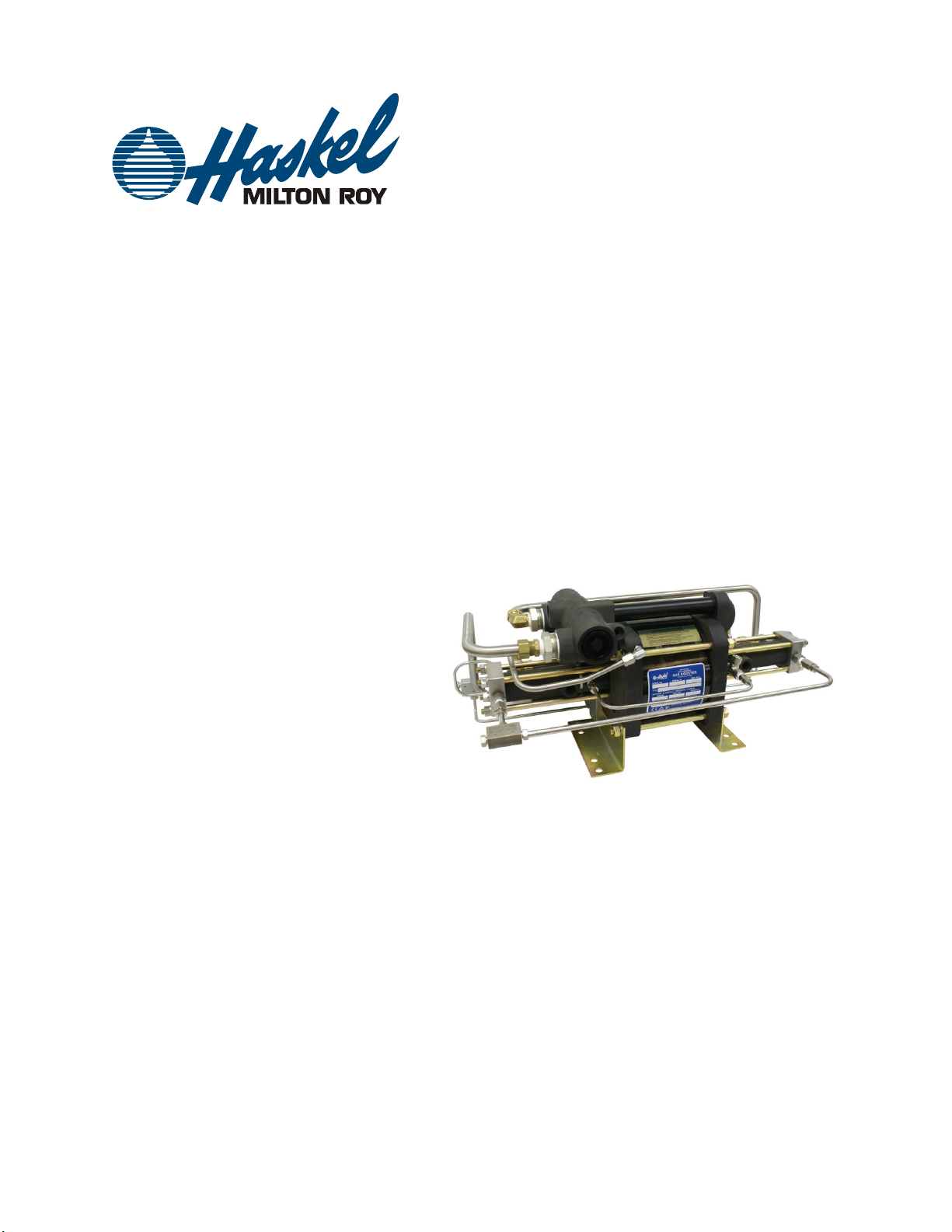
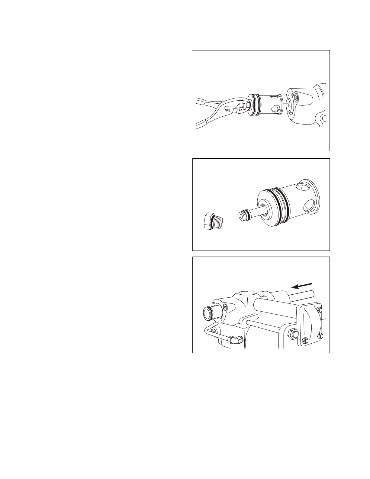
seals, retainers and bearings, all enclosed by an end cap incorporating inlet and outlet check valve
assemblies.
NOTE: The seals on the connecting rods are also considered part of the gas sections. Each rod has a
dual seal design with a small vent between to dissipate minor air drive leakage. The chambers on the
inside of the gas barrels, behind the gas pistons, are piped to a tee with a filtered breather (on standard
models). See Figures 1 & 2.
No lubrication of any kind is ever used on the dynamic seals of the gas pumping sections. They
are designed to run dry, supported on the inherent low friction properties of the seal and bearing
materials.
The life of the gas pumping section depends on the cleanliness of the gas supply. Therefore, micronic
filtration is suggested at the gas inlet port. If compressed air or other moisture containing gas is to be
pumped, the initial dew point should be low enough to prevent saturation at booster output pressure, and
if any carry over of oil from a compressed air source is evident, special coalescing type filtration may be
necessary.
Over the life of the moving parts, some migration of inert particles into the gas output should be expected.
Therefore, a small particle filter on the high pressure output line may be advisable for critical applications.
2.3.1 COMPRESSION RATIO - VOLUMETRIC EFFICIENCY (Not to be confused with "Area Ratio")
The compression ratio of any gas section is the ratio of output gas pressure to inlet gas pressure. (To
calculate, use PSI absolute values.) The gas pumping sections are designed to have minimum unswept
or clearance volume at the end of the compression stroke. On the return (suction) stroke of the piston,
output pressure in the unswept volume re-expands. This reduces the amount of potential fresh gas intake
on the suction stroke. Volumetric efficiency therefore decreases rapidly with an increase in compression
ratio. The volumetric efficiency reaches zero when the unexpelled (re-expanded) gas completely fills the
cylinder and equals the supply gas pressure at the end of the intake stroke. For example: A cylinder with
a 4% unswept volume will reach zero efficiency at a compression ratio of approximately 25:1 because the
inlet check valve will no longer open at any point during the suction stroke to admit fresh gas. Therefore,
applications requiring high compression ratios are preferably handled by the 2 stage (BAGT) models or 2
or more 8AGD models piped in series.
Production models of Haskel gas boosters are tested in the laboratory. Results of these tests indicate that
compression ratios of up to 40:1 are possible for some individual stages under ideal conditions. However,
for satisfactory operation under production conditions in industrial applications, we recommend
compression ratios (per stage) of about 10:1 or less. Operation at higher ratios per stage may not
damage the gas booster, but because output flow and efficiency will be low, the use should be limited to
pressurizing small volumes such as pressure gauge testing, etc.
2.3.2 COOLING AND EXHAUST SYSTEM
In theory, compression ratios above 3:1 with most gases produce temperatures above the allowable limits
for the seals. In practice, however, the heat of compression is transferred to the air cooled gas barrel and
adjacent metal components during the relatively slow speed of the piston on the compression stroke and
these components will stay within allowable temperature limits. Laboratory tests indicate that maximum
temperatures occur between compression ratios of 5:1 and 10:1 and have shown that exhaust air cooling
is adequate even when the booster is running at full speed. The allowable gas discharge temperature
may run as high as 150°F above ambient temperature.
Effective cooling of the gas pumping section(s) is important as service life of piston seals, bearings, and
static seals are dependent upon proper operating temperatures. Driving air expands during the exhaust
stroke with a significant reduction in temperature. Therefore, this chilled exhaust air routed through the
cooling barrels surrounding the gas barrels and shell of the plenum cooler surrounding the output and
interstage gas lines is a very efficient cooling medium.
In both the 8AGD and 8AGT series boosters the cold air drive exhaust enters the plenum cooler and is
then routed to each gas barrel cooling jacket. In the 8AGD series single stage, double acting models, the
hot high pressure output gas from both of the gas section pumps is aftercooled by passing through the
plenum cooler prior to final output. (Figure 1.)

Air Driven Gas Booster Compressor, 8” Drive AG Series • OM-12J
4
Figure 1. 8AGD Series Aftercooling Diagram.
In the 8AGT series two stage boosters (Figure 2.), where higher maximum temperatures can result due to
high compression ratios, the hot output gas line from the first stage pump is "intercooled" by passing
through the plenum cooler prior to entering the second stage pump. The hotter, higher pressure output
line from the second stage pump is then "aftercooled" by passing through the plenum cooler prior to the
final output port.
Figure 2. 8AGT Series Intercooling / Aftercooling Diagram.
Under certain severe operating conditions, it may be necessary to slow down the cycling of the gas
booster to prevent overheating. It is very difficult to predict exactly when overheating may occur. To test,
install a thermocouple approximately one inch from the discharge port of the gas pumping section.
Temperatures above 300°F at this point will shorten gas piston seal life considerably.

Air Driven Gas Booster Compressor, 8” Drive AG Series • OM-12J
5
3. Installation
3.1 Mounting
All models will operate in any position required for system operation. However, for Oxygen Gas Boosting
applications, mount all models horizontally with mounting brackets down.
3.2 Environment
All units are protected with plating or materials of construction for installation in normal indoor or outdoor
applications. Special considerations may be advisable on some components if atmosphere is corrosive. If
ambient temperatures will drop below freezing, dryers to prevent condensation of moisture in either the
drive or gas section are advisable.
3.3 Drive System
Incoming air (or gas) piping and components must be large enough to provide sufficient flow for the cycle
rate desired. Minimum size to provide the pumping rates shown in the current catalog is 3/4” I.D. Complex
lines over a considerable distance should be 1” or larger.
The standard drive inlet is a 3/4” female pipe port located in the center of the cycling valve body. As
standard, the pilot air (or gas) to the cycling system is provided through the bent tube assembly from the
1/4” NPT tap below the 3/4” NPT drive inlet port. For external remote pilot, the tube assembly is removed,
the 1/4” NPT tap is plugged, and the pilot air from an alternate source connected to the 1/8” NPT port in
the valve end cap. External pilot pressure should be equal to or exceed drive pressure. The air drive (and
air pilot if external) inlet system should always include a filter since essentially all compressors introduce a
considerable amount of contamination.
The drive requires approximately 25 psi to trigger the valve spool and pilot piston as lubricated at the
factory. It is not necessary or desirable to use an airline lubricator.
3.3.1 MUFFLERS
For minimum noise level, these may be remotely located. If beyond 6 feet, use 3/4” I.D. pipe, tube or
hose.
3.3.2 PILOT VENT
The pilot system vents a small amount of pilot air (or gas) once per cycle from the 1/8” NPT tap in the flow
fitting end cap. This vent should operate unobstructed. It may also be piped to a remote location if the
pilot gas is hazardous. Vent purge modification with a 15 psi relief is available. Specify modification 56611
for single-ended models and 56611-2 for double-ended models.
3.4 Controls
For general usage the optional standard air controls accessory package includes a filter, an air pressure
regulator with a gauge, and a manual valve for shutoff and speed control. Pumping rates shown in the
current catalog are based on the use of a regulator with a flow capacity equivalent to 3/4” pipe size.
A number of other control options are available to suit specific applications. Among these are: Automatic
start/stop of the drive - sensing gas output and/or gas inlet pressures; high pressure safety relief
protection; cycle counting, cycle rate control, etc.
Consult current catalogs, authorized distributors or the factory.
3.5 Gas System
Refer to Figures 1 or 2 and to the detailed installation drawings enclosed covering the specific model. The
installation drawing will provide inlet and outlet port detail and location. When tightening connecting
piping, hold the port fitting securely with a backup wrench. Be certain that the connecting lines and fittings
are of the proper design and safety factor for pressurized gas service.
NOTE: Also see paragraph 2.3 on gas system cleanliness.

Air Driven Gas Booster Compressor, 8” Drive AG Series • OM-12J
6
4. Operation and Safety Considerations
NOTE: Before operation be sure the gas supply has been turned on to the booster inlet and allowed to
flow through and equalize into the downstream system and/or receivers.
4.1 Starting the Drive
Turn on the drive air (or gas) gradually. The pump will automatically start to cycle with the application of
approximately 25 psi to the inlet and air pilot.
NOTE: On initial start, or if unit has been idle for an extended period of time, the starting drive pressure
may have to be somewhat higher.
Observe the buildup in output pressure with a conveniently located gauge rated for the maximum system
pressure.
Maximum output pressure can be automatically controlled by a Haskel air pilot pressure switch or similar
device backed up by a safety relief valve. (Refer to current catalogs for complete details.) In some
applications, the unit may also be allowed to simply pump-up to its maximum pressure and stall - provided
that ample strength allowance for outlet system piping and valves has been included.
Leaving the drive and liquid sections pressurized for extended periods is not detrimental to the unit but
may be inadvisable for safety considerations depending on the installation.
5. Maintenance
5.1 General
WARNING: Use any cleaning solvent in a well ventilated area. Avoid excessive contact with skin. Keep
away from extreme heat and open flame.
Disassemble equipment only to the extent required to repair or replace defective parts. Do not disturb
unaffected component parts or plumbing connections.
NOTE: Detailed assembly drawings particular to your specific model have been included as a part of
these maintenance instructions. Consider these maintenance instructions as general information while
the assembly drawings reflect detail information, directly related to your particular drive/pump unit.
Certain assemblies, rarely requiring disassembly for servicing, have been assembled with Loctite CV
(Blue) No. 242, as a locking compound. (Refer to NOTES column in assembly drawing.) If disassembly of
these parts is essential, they should be carefully cleaned and then reassembled using Loctite CV. Use
care to avoid getting compound into other joints or moving parts.
It is good maintenance practice to replace bearings, seals, o-rings and backup rings (refer to NOTES
column on applicable assembly drawing for seal kit (s) available) whenever equipment is opened for part
inspection and/or replacement.
Air Drive Section
Parts removed for inspection should be washed in an aqueous based industrial cleaner, free of V.O.C.,
such as Blue Gold or equivalent. Avoid use of Trichlorethylene, Perchlorethylene, etc. Such cleaners will
damage seals and finish on air barrel and end caps.
Gas Pumping Section
Parts should preferably be washed in an aqueous based industrial cleaner, free of V.O.C., such as Blue
Gold or equivalent.
Inspect moving parts for evidence of wear (scoring or scratches) due to foreign material. Inspect all
threaded parts for crossed or damaged threads. Replace part if thread damage exceeds 50 percent of
one thread, if less than 50 percent, chase threads with appropriate tap or die.
5.2 Cycling Valve Assembly
While continually referring to your detailed assembly drawing, disassemble cycling valve assembly in the
following manner:

Air Driven Gas Booster Compressor, 8” Drive AG Series • OM-12J
7
5.2.1 Note method of lockwiring screws. Remove and discard safety wire. Remove (4) screws and washer
and lift off retaining plate.
5.2.2 Grasp hex plug and carefully pull pilot piston
assembly with cap from valve body. (Ref. Fig. 3.)
Remove boss o-ring sealed hex plug. Push shaft out
of the cap to reveal o-ring on end of shaft. (Ref. Fig.
4.)
Inspect all static and dynamic seals and replace any
that are damaged, worn or swollen. (If any special
tools are required, it will be noted on the detailed
assembly drawing.)
5.2.3 Reach inside valve body. Remove first plastic
bumper. Carefully pull out spool. Inspect (2) spool
seals and replace any that are damaged, worn or
swollen. If spool cannot be pulled out, remove
cartridge from opposite end of casting and push
spool out with a rod or screw driver. (Ref. Fig. 5.)
Use a flashlight to inspect second (inner) bumper at
the end of the sleeve. If this bumper is in place put all
parts back as follows.
Figure 3. Cycling valve cap with pilot
piston
Figure 4. Pilot shaft end seal
Figure 5. Pushing from opposite end to
remove valve spool

Air Driven Gas Booster Compressor, 8” Drive AG Series • OM-12J
8
5.2.3.1 Reinstall hex plug with o-ring. Lubricate spool
seals including pilot piston seal. (Ref. 2.2.1) Insert
pilot piston into spool with bumper hanging loose on
pilot piston shaft. (Ref. Fig. 6.)
Guide in all parts by first inserting small end of spool
into interior of sleeve and seating bumper on end of
sleeve. Secure parts with retainer plate, (4) washers
and screws. Tighten screws to 30 inch pounds
torque. Retest for proper operation. If successful,
install new safety wire on cap screws.
5.2.4 If further disassembly is necessary, repeat prior
steps (5.2.1 thru 5.2.3) and then carefully remove
sleeve and second bumper.
NOTE: To remove sleeve, insert a blunt hook tool
(such as tool p/n 28584, brass welding rod or equally
soft metal) into a crosshole in the sleeve, and pull
sleeve from the valve body. (Ref. Fig. 7.)
5.2.5 Inspect (4) o-rings on sleeve and discard any
that are damaged, worn or swollen.
5.2.6 Discard second (inner) bumper if damaged or
worn.
5.2.7 Apply Haskel 50866 Lubricant liberally to all o-
rings.
5.2.8 Install inner bumper on bottom of bore in valve
body. Lay sleeve end inner o-ring on inner bumper.
With two middle o-rings installed on sleeve, slide
sleeve in against inner o-ring and bumper. Then to
“seat” fourth (outer) o-ring evenly into the groove on the end of sleeve, use bare cap/pilot piston assembly
as a seating tool.
5.2.9 Repeat installation of remaining parts per paragraph 5.2.3.1
5.3 Pilot Stem Valves
NOTE: Before repair, test according to paragraph 5.4.
Disassemble pilot valves in the following manner (while referring to your detailed assembly drawing):
NOTE: The following procedures reflect removal of the pilot valve from both the control valve end cap and
flow fitting end cap of drive section. Use applicable paragraphs depending on which pilot valve is to be
inspected and/or repaired.
5.3.1 Disconnect all plumbing lines necessary to allow separation of cycling valve assembly from position
on end cap.
5.3.2 Using suitable wrench to hold long nut. Remove bolt, lock washer and flat washer located on
topside of flow fitting.
5.3.3 Remove (2) capscrews, lock washers and flat washers located on underside of cycling valve
assembly (or flow fitting). Using care to prevent damage or loss of small parts, lift cycling valve assembly
(or flow fitting) from end cap. Remove spring, o-ring and pilot valve stem.
5.3.4 Remove flow tube and pilot tube. Inspect o-rings on ends of both tubes and replace any if damaged,
worn or swollen. Relubricate with 50866 lubricant.
5.3.5 Inspect pilot valves for damage. Replace valve if stem is bent or scratched.
5.3.6 A molded seat valve is used under the flow fitting, while a replaceable o-ring seat valve (with orifice)
is used under the cycling valve assembly. Inspect replaceable o-ring and replace if damaged, worn or
Figure 6. Cycling valve cap and parts
ready for insertion into valve body
Figure 7. Pulling out sleeve with a hook
on soft metal rod

Air Driven Gas Booster Compressor, 8” Drive AG Series • OM-12J
9
swollen. Inspect molded seat on opposite pilot valve. If damaged, replace pilot valve. The molded seat
pilot valve under the flow fitting uses the shorter of the two springs.
NOTE: Unless excessive leakage occurs, it is not
advisable to replace the inside seal on the stem of
either pilot valve as this requires disassembly of the
air drive cylinder. If replacement is required, care
must be taken in installing the Tru-Arc retaining ring
concentrically as shown in (Fig. 8.) Using the pilot
stem valve with the molded seat as a seating and
centering tool, put the retaining ring, retainer and
seal on the stem so that the molded rubber face of
the valve is against the retaining ring. Insert in seal
cavity. Tap the top of the pilot valve lightly with a
small hammer to evenly bend the legs of the
retaining ring.
5.3.7 Apply Haskel 50866 Lubricant to pilot valve
parts and reassemble in the reverse manner.
5.4 Pilot System Testing
If the air drive will not cycle, the following test procedure will determine which of the pilot valves is faulty:
5.4.1 Remove gauge port pipe plug (p/n 17568-2) located in the cycling valve body, next to the retaining
plate.
5.4.2 Install pressure gauge (0 to 160 PSI or higher) in 1/8" NPT port.
5.4.3 Apply air pressure to the air drive inlet (and external pilot if so equipped). Gauge will read low
pressure until pilot valve on cycling valve end is contacted by drive piston and it reverses direction, Then
gauge will read full pilot air pressure until opposite pilot valve (on flow fitting end) is contacted-venting the
pilot pressure. Correct pilot valve action therefore will cause gauge to "snap" immediately from low to high
as drive reciprocates. A slow increase in gauge reading indicates leakage past replaceable O-ring on pilot
valve located under the cycling valve assembly. A slow decrease in pressure indicates leakage past the
molded seat on pilot valve located under the flow fitting. Check also for correct spring length (Ref.
paragraph 5.3.6) and external air leaks at gauge plug, or ends of pilot tube.
5.5 Air Drive Section
Disassemble air drive cylinder section and piston in the following manner (while referring to your detailed
assembly drawing):
5.5.1 Disconnect all plumbing lines to allow gas pump sections be moved left or right when drive section
is separated.
5.5.2 Remove bolt, lock washer and flat washer (hold long nut to prevent unscrewing) located on topside
of flow fitting.
5.5.3 Remove (8) nuts. lock washers and flat washers securing (4) air drive main tie bolts and carefully
separate drive end caps (with intact gas pump sections) to gain access to drive piston and cross pins
securing rod to drive piston assembly.
5.5.4 Remove (1) E-ring, push out (1) cross pin and disconnect (1) piston rod from piston assembly so
that air barrel and drive piston o-ring can be removed for inspection.
Figure 8. Centering and installing seal
retaining ring using pilot step as tool

Air Driven Gas Booster Compressor, 8” Drive AG Series • OM-12J
10
5.5.5 Inspect barrel to end cap static seal o-rings.
Pull barrel off drive piston and inspect large drive
piston seal.
NOTE: If the large o-ring is “tight” in the groove, it is
probably swollen and should be replaced.
Replace if damaged or worn. Also, check large drive
piston o-ring for shrinkage by laying it on a flat
surface. Then place a clean unlubricated air barrel
over it. The o-ring outside diameter must be large
enough so that it can be picked up with the barrel. If
not, discard and replace. (Ref. Fig. 9.)
5.5.6 Clean all parts and inspect for grooved,
scratched or scored wear surfaces.
5.5.7 Apply Haskel 50866 Lubricant to all o-rings and inner surface of barrel and reassemble drive section
parts, end caps with pump sections, gas and associated plumbing lines in reverse order of disassembly
instructions.
5.5.8 Alternately (crosswise) torque tie rod nuts to 250 to 300 in-lbs.
5.6 Gas Check Valves
NOTE: The most obvious symptom indicating check valve repair is needed is that the gas end cap does
not heat up during operation. This means that little or no compression is occurring. (See also Paragraph
6. COMPRESSION TEST).
The parts makeup of the 8AGD series inlet and outlet check valves are the SAME for both gas piston end
caps; whereas the 8AGT series inlet and outlet check valves may be DIFFERENT for opposite gas piston
end caps. While the parts may be Identical for a particular series pump, it is important to note the
variations of position that relate to the location of these parts relative to the assembly of the
interconnecting gas piping and to refer to your detailed assembly drawing during repair.
5.6.1 Disconnect all plumbing lines necessary to allow access to the check valves.
5.6.2 Using suitable wrench, unscrew port fitting from end cap. Inspect O-ring on fitting and replace if
damaged, worn or swollen.
5.6.3 Remove remainder of parts inside check valve and inspect for damage or wear. Seats and O-rings
are most likely parts requiring replacement and are coded on the assembly drawing for kit replacement.
5.6.4 Clean all parts (Ref. paragraph 5.1) and inspect for nicks, grooves and deformation and renew any
that are damaged.
5.6.5 DO NOT apply lubricant to any of these parts.
NOTE: To properly center the parts during reassembly, we recommend that the ports be in a vertical
position. This may require the removal of the end cap in some instances.
5.6.6 Reassemble check valve parts in order shown on assembly drawing detail. Refer to assembly
drawing for special notes including torque required for tie rod nuts.
5.7 Gas Pistons
NOTE: Minute leakage of inlet gas past a high dynamic pressure gas piston seal is normal and can
usually be felt at the cross connected 21703-2 breather cap port with finger pressure (drive not cycling).
Audible leakage however indicates excessive gas piston seal wear. Disassemble gas pistons while
referring to your detailed assembly drawing in the following manner:
5.7.1 Disconnect all plumbing lines necessary to allow removal of gas section end caps.
5.7.2 Remove (4) nuts and lock washers from gas pump section tie rods.
NOTE: At this point, it is recommended that the entire gas section be pulled off as a unit from the drive
section by releasing the piston rod from the drive piston per Paragraphs 5.5.3 and 5.5.4. Then clamp the
gas end cap (or retaining plate) in a vise and proceed with further disassembly and reassembly.
Figure 9. Checking drive piston o-ring
for shrinkage

Air Driven Gas Booster Compressor, 8” Drive AG Series • OM-12J
11
5.7.3 Remove end cap and/or retaining plate. Inspect O-ring and back up ring mounted inside end cap
and replace if damaged, worn or swollen.
5.7.4 Remove cooling sleeve (with attached muffler), high pressure gas barrel and static seal O-rings.
Inspect O-rings and replace if damaged, worn or swollen.
5.7.5 The remainder of disassembly depends upon the parts make up shown on your particular assembly
drawing. The extent of disassembly should be determined by the initial reasons for disassembly; that is
end cap seal leakage, gas piston seal leakage, or air drive rod seal leakage. O-rings, seals and backup
rings are the most likely parts requiring replacement and are coded for kit replacement.
5.7.6 Clean all parts (Ref. Paragraph 5.1) and inspect for nicked, grooved, scratched or scored wear
surfaces and believille spring deformation.
5.7.7 Replace all parts that are damaged. Inspect high pressure gas barrel bore with a strong light. It
must be “mirror smooth”. However, if only slightly scratched it may be salvaged with a light hone.
NOTE: DO NOT apply a lubricant of any kind to bearings, seals, O-rings, backup rings or inner surface of
gas barrel.
5.7.8 Reassemble gas piston parts in reverse order of disassembly. Final tightening and cotter pinning of
gas piston nut must be done with parts inside gas barrel. Refer to assembly instructions on assembly
drawing for final details.
5.7.9 Alternately (crosswise) torque tie rods nuts to maximum torque value per assembly drawing notes.
6. Compression Test –Gas Section and Check Valves
6.1 Purpose
Quick evaluation of the integrity of any individual pump section (before or after repair).
6.2 Theory - Drive Section
Each gas booster pump end consists of a sealed piston reciprocating in a smooth bore gas barrel;
inhaling gas on the backstroke through the inlet check; expelling most of this gas on the forward stroke
through the outlet check.
Therefore: THE CONDITION OF ALL THESE PARTS CAN BE MEASURED BY COMPRESSING AIR
DIRECTLY FROM ATMOSPHERE INTO A 1000 PSlG GAUGE ON ANY PUMP SECTION OF ANY
MODEL.
6.3 Schematic

Air Driven Gas Booster Compressor, 8” Drive AG Series • OM-12J
12
6.4 Test:
Install gauge. Cycle drive at moderate speed until pressure stops rising. Record maximum pressure.
6.5 Analysis:
6.5.1 If the following pressures are achieved, the gas section condition should be considered satisfactory:
Model Number
Pressure PSIG Minimum from Atmospheric Inlet
8AGD -5
225
8AGD -14
225
8AGD -30
250
8AGD -60
315
If maximum pressure is less than the minimum, excessive leakage is occurring at the piston seal; and/or
the inlet check; and/or the outlet check.
6.5.2
Symptom Observing Gauge Pointer
Repair
A. Fast fall back from maximum.
A. Outlet Check
B. Sluggish rise during pressure stroke.
B. Inlet Check and/or Piston Seal/Gas Barrel
If symptom B: DISCONNECT DRIVE AIR SO UNIT CANNOT CYCLE.* Apply 80 to 500 PSI clean and dry
air or gas to gas inlet port.
If leakage out vent tube is audible, piston seal is defective and/or gas barrel is scored.
If leakage out vent is barely detectable, inlet check is the problem. Disassemble and repair.
* CAUTION - NEVER CYCLE UNIT WITH PRESSURE APPLIED TO GAS INLET PORT WHEN GAUGE
IS IN OUTLET PORT. GAUGE WILL BE OVERPRESSURED.

Air Driven Gas Booster Compressor, 8” Drive AG Series • OM-12J
13
7. Troubleshooting Guide
7.1 Symptom
7.2 Possible Cause
7.3 Remedy
Drive will not start nor
cycle with at least 25
psi drive pressure.
Air supply blocked or inadequate.
Check air supply and regulator.
Cycling valve spool binding.
Clean spool by following cycling
valve disassembly instructions.
(Ref. paragraph 5.2)
Either pilot valve stem too short.
Replace defective pilot valve.
Exhaust or vent “iced up”.
Too much moisture in drive air.
Install better moisture reduction
system.
Mufflers plugged.
Remove, disassemble and clean
mufflers.
Drive will not cycle
under load and pilot
vent leaks air
continuously.
Broken pilot charge valve spring (cycling
valve end) causing it to stick open. Then
the pilot vent valve cannot “dump” enough
pilot pressure so it remains held open by
the drive piston.
Replace spring.
Defective o-ring on pilot charge valve
(cycling valve end) causing high leakage
into the pilot system.
Replace o-ring.
Drive will not cycle.
Mufflers leak drive air
with very audible
“hiss”.
Insufficient drive air volume causing
cycling spool to hang up in midstroke or
drive-piston o-ring to bypass air.
Increase drive air line size.
Shrinkage or damage to spool seals
and/or large drive piston seal.
Inspect spool seals first.
(paragraph 5.2 ) If damaged,
replace and retest. If not
damaged, disassemble drive
and check large o-ring size per
Figure 9 and paragraph 5.5.5.
Drive cycles but gas
section(s) does not
pump. (End cap does
not heat up)
Check valve(s) not seating, and/or
leakage of plunger or piston seal
(paragraphs 5.6, 5.7).
See compression check
procedure and analysis
(paragraph 6).

空気駆動ガス昇圧圧縮機 8 インチ駆動AGシリーズ • OM-12J
14
1. はじめに
この取扱説明書に記載の内容は、8AGシリーズ空気駆動ガスブースタに適用されるものです。対応する基本モ
デルは、8AGD-5、-14、-30、-60、および8AGT-5/14、-5/30、-14/60、-
30/60です。この内容は、特定の目的で基本モデルに特別な改造を施したもの、例えば特殊シールや特別な材料
を通常以外の駆動気体、搬送気体に使用するものや、特別な環境のために使用しているもの、特定の接続口の
もの、特別部品を使用しているものなどにも適用されます。これらのオプション改造に関しては、本書では詳細に
記載されていません。これらについては、出荷時に添付される特殊部品/改造リストや説明図に詳細に書かれて
います。
このガスブースタは、大流量、空気(通常)駆動、往復ピストン型、無潤滑、オイルフリーのガスブースタで、単段
複動(8AGDモデル)および2段(8AGT)の2つのタイプをご利用いただけます。モデルの –
以下の番号は、駆動空気ピストンとガス圧縮ピストンの概略の面積比です。すなわち、8AGD-
5は、空気駆動ピストンの実効面積が、両方のガス圧縮ピストンの面積の約5倍、8AGT-
5/14は、1段目では空気駆動ピストンの面積がガスピストンの約5倍、2段目では約14倍です。
2. 解説
2.1作動原理
装置の中央にある空気駆動ピストンは、戻り止めの無い、不平衡4方空気弁スプールによって圧力を受けて自動
的に往復動します。このスプール弁はパイロット空気システムにより、交互に一方が加圧、もう一方が排気される
ように切り替わります。パイロット空気は、駆動ピストンにより機械的に作動される2つのパイロット空気弁により
制御されます。この空気駆動部は直接、両側に反対向きに設置された2つの気体昇圧ピストンに接続されていま
す。気体昇圧ピストンは無給油の乾燥状態で運転するように設計されています。このため、供給された気体は炭
化水素の汚染を受けることなく必要な圧力に昇圧されます。
駆動空気の排気(作動後の膨張により温度が低下する)は気体ピストンバレル(ジャケットを通して)、高圧出口、
および中段気体配管(プレナム冷却器を通して)の冷却に使用されます。
2.2 空気駆動部
各装置に添付されたサイクル弁と空気駆動部の詳細組立図をご参照ください。空気駆動部は駆動ピストンユニッ
ト、不平衡スプール型4方サイクル弁ユニットと2つのパイロットステム弁から成り立っています。入出口としては、
駆動空気入口、2つの大きい排気口、パイロット入口、パイロットベント、およびパイロットユニット用圧力計取付口
(閉止栓)があります。NPTネジが標準です。
一方のパイロット弁は制御弁エンドキャップについており、もう一方は接続フィッティングエンドキャップについてい
ます。連絡管は、駆動空気の流れを弁エンドキャップから反対側エンドキャップに接続しています。パイロット管は
、2つのパイロット弁を直列に接続しています。サイクルスプール弁はバネや戻り止め無しで運転され、パイロット
弁によって繰り返し作動します。スプール弁の端に入っているパイロット弁の大きい部分に、加圧と排気を交互に
行います。パイロットベントの排気口はエンドキャップの接続フィッティングにあります。
2.2.1 潤滑
工場組立時に、シリコングリス(ハスケル部品番号50866)が全ての可動部分とシール(空気駆動部のみ、ガス
部は適用外)に薄く塗布されています。稼動状況に応じて、時折このグリースを作業し易いサイクルスプールシー
ルに塗布することをお勧めします。5.2.3.1項をご参照ください。無給油運転オプション54312をご利用いただくこ
ともできます(有料)。これにより、追加潤滑を行わずに連続運転することができます。
必ず、通常のボウルタイプの工場用空気フィルター・水分分離器を取り付けて(工場組立時に取り付けられている
場合は不要)、定期的に点検してください。このフィルター・分離器は駆動空気入口配管と同じか、より大きい配管
径のものとしてください。
エアオイラーは使用しないでください。

空気駆動ガス昇圧圧縮機 8 インチ駆動AGシリーズ • OM-12J
15
2.3 気体昇圧部
各装置に添付されたサイクル弁と気体搬送部の詳細組立図をご参照ください。各気体搬送部は冷却ジャケット付
きの気体バレル、高圧移動シール、リテイナー、および軸受付きのピストンユニットからできており、すべては流入
側および流出側逆止弁ユニットが付いているエンドキャップの内側にはいっています。
注意:コネクティングロッドについているシールは、気体部の一部です。各ロッドは二重シール構造になっていて、
少量の駆動空気の漏れを逃がすためのベントがついています。気体バレルの内側のチャンバー(気体ピストンの
後ろ)はフィルター付きのブリーザーにT字管で接続されています(標準モデル)。
気体搬送部にはいかなる種類の潤滑も使用しないで下さい。この部分は、低摩擦材料をシールおよび軸受に使
用して、乾燥状態で運転するように設計されています。
気体搬送部の寿命は供給気体の清浄度によります。このため、マイクロフィルターを気体流入口に設置すること
をお勧めします。水分を含んだ圧縮空気やその他の気体を搬送する場合、初期状態での露点は十分低いはずで
すので、昇圧機流出口圧力での結露は避けられます。空気圧縮機から空気源による油の持込が認められる場
合、特殊な複合型フィルターが必要になります。
可動部品の寿命に従って、不活性の微粉末が気体の流出側に含まれる可能性があります。高度な用途に対して
は、高圧流出配管に微細な粒子フィルターを設置して下さい。
2.3.1 圧縮比 (容積効率)(面積比と混同しないようにしてください。)
昇圧部の圧縮比は、流入圧力に対する流出圧力の比です。(計算には絶対圧を使用してください。)気体搬送部
は圧縮行程の最後に、最小すきま体積(死点容積)を持つように設計されます。ピストンの戻り(吸込)行程では、
すきま体積の流出圧力は再度膨張します。これにより、吸込行程で新たに入ってくることができる気体の量が減
ります。このため、容積効率は圧縮比の上昇により、極端に減少します。排出されない(再膨張した)気体がシリ
ンダーを完全に満たした場合、体積効率はゼロとなり、供給気体圧力と吸込行程の最後では同じになります。例:
死点容積が4%のシリンダーは、圧縮比が約25:1のとき、効率ゼロとなります。なぜならば、流入側逆止弁は吸
込行程のいかなる時点でも開かず、新しい気体を吸込めないからです。従って、高圧縮比が必要な用途では、2
段(8AGT)モデルを使用するか、2台以上の8AGDモデルを直列に接続をしようする方が好ましいことになります
。
ハスケル気体昇圧機の量産モデルは実験室で試験されています。この実験の結果、理想的な状態では、各段で
最高40:1までの圧縮比が可能であることが示されました。しかし、工業的な用途での製造条件のもとで充分な運
転を行うためには、圧縮比(一段につき)は10:1以下を推奨します。これより高い圧縮率(一段につき)の運転を
行っても、気体昇圧機を損傷することはありませんが、流出側の流量と効率は低くなるので、用途は小体積を圧
縮するもの(圧力計の試験など)に限られます。
2.3.2 冷却と排気システム
理論上、圧縮比が3:1より高いと、ほとんどの気体はシールの許容範囲より高い温度になります。実際には、圧
縮による熱は、比較的速度の遅い圧縮行程の間に、空冷の気体バレルと接している金属部品に逃げるため、各
部品は許容温度範囲内にとどまります。実験室での実験によると、圧縮比5:1と10:1の間で最高温度に達します
。また、駆動空気排気による冷却は、昇圧機が最高速度で運転しているときでも十分であることを示しています。
気体の許容できる排出温度は大気温度より80°C あまり高くなる可能性があります。
気体搬送部の効果的な冷却は、適正な運転温度かどうかによって、ピストンシール、軸受、固定シールの寿命に
大変重要な影響を与えます。駆動空気は排気行程で膨張し、温度の極度の低下をもたらします。この低温の排
気を、気体バレルの周囲の冷却バレルと、気体の流出管と段間の連絡管の周囲のプレナム冷却器のシェルに導
くことは、大変効果的な冷却方法です。)

空気駆動ガス昇圧圧縮機 8 インチ駆動AGシリーズ • OM-12J
16
図18AGDシリーズ後冷却系統図
8AGTシリーズ2段昇圧機(図2)では、圧縮比が高いため、気体の最高温度がさらに高くなるため、一段目の搬
送機の流出気体をプレナム冷却器で2段目の搬送機に入る前に中段冷却します。二段目の搬送機から流出する
より高温高圧の流出配管は、最終流出口へ行く前にプレナム冷却器を通り、さらに後冷却されます。
図28AGTシリーズ中段冷却・後冷却系統図
特に運転条件が厳しい場合、オーバーヒートを避けるために、ガスブースタの運転速度を下げる必要があること
もあります。どの時点でオーバーヒートとなるかを正確に予想することは大変困難です。試してみるためには、熱
電対を気体搬送部の排出口から約25mm の位置に取り付けます。この位置で145°C
を越える温度に達すると、ピストンシールの寿命は相当短くなります。

空気駆動ガス昇圧圧縮機 8 インチ駆動AGシリーズ • OM-12J
17
3. 設置
3.1 据付
全モデルとも用途に合わせていかなる位置でも運転できます。しかし、酸素昇圧用では、全モデルとも水平に据
付ブラケットを下向きに据え付けてください。
3.2 作動環境
全機種とも通常の室内または屋外の使用に耐えるよう、メッキあるいは構成材料によって保護されています。環
境が腐食性の場合、一部の部品に対しては特別の配慮が必要になります。外気温が氷点以下に下がる場合、
駆動空気と気体部の両方に水分の凝縮を避けるための乾燥機を設置することをお勧めします。
3.3 運転システム
流入空気配管と機器は、必要な運転条件を得ることができる流量の空気を供給するできるだけ、十分大きくなく
てはなりません。このカタログに示された搬送率を得るための配管の最小径は、内径19.05 mm
です。相当に長い、複雑な管路を使用する場合は、この管径は25.4 mm 以上とすべきです。
標準の駆動空気入口は、3/4B (20A)
内ネジ管接続口で、サイクル弁本体の中央についています。標準でサイクルシステムへのパイロット空気の供給
は、3/4B (20A)駆動空気入口の下1/4B (8A)NPT
接続口からのベント管ユニットを通しておこなわれます。外付けパイロットでは、1/4B
(8A)NPT接続口にはプラグを付け、配管ユニットははずされ、代わりの空気源からのパイロット空気が弁エンドキ
ャップの1/8B
NPT接続口に供給されます。外付けパイロット空気圧は駆動空気圧と同じか、それ以上としてください。
駆動空気(外付けの場合はパイロット空気も)流入システムには、必ずフィルターを入れてください。本質的には、
いかなるコンプレッサーも、圧縮空気に相当量の汚れを持ち込むので、必要です。
工場で潤滑した状態で、空気弁のスプールとパイロット空気ピストンを動かし始めるためには、約1 bar
の駆動空気が必要です。エアオイラーは使わないようにしてください。
3.3.1 マフラー
騒音を最低限に抑えるためには、離して取り付けてください。1.8 mを越える場合には、内径19.5
mmの管またはホースを使ってください。
3.3.2 パイロットベント
パイロットシステムは少量のパイロット空気を各行程ごとに一度 接続フィッティングエンドキャップの1/8B (8A)
NPTのベント口から排出します。このベントは障害無く使えるようにしてください。
3.4制御
一般的な用途のために、標準空気制御部品パッケージを追加することができます。このパッケージには、フィルタ
ー、圧力計付き圧力調整弁、および手動式閉止兼調速弁が入っています。このカタログに示された気体搬送量
は3/4B (20A)配管と同等の空気流量を許容する調圧弁を使用するものとしています。
その他にも特定の用途に合った制御方法として、利用できるものが何種類もあります。これらの中には、自動運
転・停止(気体入口または出口の圧力感知による)、可変背圧制御、高圧安全弁保護、高圧気体源による駆動制
限、運転回数計数、などがあります。
このカタログをご参照いただくか、代理店、または工場にご相談ください。

空気駆動ガス昇圧圧縮機 8 インチ駆動AGシリーズ • OM-12J
18
3.5気体システム
図1または2および各装置に添付された詳細設置図をご参照ください。設置図には流入口と流出口の位置と詳細
が示されています。接続する管を締めるときには、別のスパナで接続口のフィッティングをしっかりと保持してくだ
さい。接続する配管とフィッティングが、高圧の気体を取り扱うのに安全で適切な設計となっていることを必ず確
認してください。
注意:気体システムの清浄度に関して、2.3項もご参照ください。
4. 運転、安全対策
注意:運転を行う前に必ず気体供給源から昇圧機への供給を始め、気体が昇圧機の下流の設備または受入容
器まで流れ、圧力が均圧になっているようにしてください。
4.1 運転開始
駆動空気を徐々に供給してください。駆動空気入口と空気パイロットの圧力が約1
barに達すると、昇圧機は自動的に運転を始めます。
注意:最初に運転を開始するとき、または装置が長い間運転されなかったとき、運転を開始する駆動空気圧力は
やや高いことがあります。
出口側の圧力が上がっていく様子を、出口の最高圧力の定格の適当な圧力計で観察してください。
最高出口側圧力は、通常空気パイロット圧力スイッチ、または安全弁付きの同様の装置で自動的に制御されま
す。(詳細についてはカタログをご参照ください)用途によっては、装置は単純に最高圧力まで運転し、せき止め
状態になって停止します。出口系統の配管や弁には十分な強度の余裕をみてください。
駆動空気部と気体部を加圧した状態で長い間放置することは装置にとって有害ではありませんが、設置の状態
によっては、安全性の見地からは望ましくありません。
5. 保守
5.1概要
警告:清掃用の溶剤はよく換気された場所で使用してください。溶剤から出たガスを吸ったり皮膚に必要以上に
接触するのを避けてください。高い熱や引火する可能性のある火には近づかないようにしてください。
機器の分解は不良な部品の修理または交換の必要がある場合のみにしてください。関係の無い部品や配管の
接続に支障を与えないようにしてください。
注意:お客様の設備の特定の詳細組立図は保守要領書の一部として含まれています。組立図はお客様の特定
の気体昇圧・圧縮機に直接関係のある詳細情報を示しているのに対し、この保守要領書は一般的な情報とお考
えください。
保守のために分解する必要がほとんど無い一部のユニットでは、ロックタイトCV(ブルー)No.242を回り止めとし
て使用して組み立てています。(組立図の備考欄をご参照ください。)こうした部分の分解が必要な場合、注意深
く洗浄し、組み立てる際にはロックタイトCVを使用してください。ロックタイトが他の接続部や可動部に付着しない
ようによく気をつけてください。装置を点検や部品交換のために分解作業するとき毎回、軸受、シール、Oリングお
よびバックアップリング(シールキットについて適用される組立図の備考欄を参照)を交換するのは保守のために
は良い方法です。
空気駆動部
点検のために取り外した部品は、ストッダード溶剤、無鉛ガソリンなどで洗ってください。トリクロロエチレン、ペル
クロロエチレンなどの使用は避けてください。これらの洗剤は、シールや空気バレルとエンドキャップの表面仕上
げを傷めます。

空気駆動ガス昇圧圧縮機 8 インチ駆動AGシリーズ • OM-12J
19
気体搬送部
部品はイソプロピルアルコール(IPA系、精密洗浄剤)で洗浄するのが最適です。
可動部品に異物による磨耗の跡(引っかき傷や切り傷)がないか点検します。全てのネジがある部品にネジの損
傷がないか点検してください。ネジの損傷が一つのねじの50%を超えている場合、部品を交換してください。損傷
が50%以下の場合、ネジを正しいタップまたはダイスでさらえてください。
5.2 サイクル弁ユニット
詳細組立図を引き続き参照しながら、サイクル弁ユニットを以下の要領で分解してください。
5.2.1
ロックワイヤ付きのネジに注意してください。安全ワイヤを取りはずし、廃却してください。4つのネジとワッシャー
をはずし、リテイニングプレートを持ち上げてはずしてください。
5.2.2
六角プラグをつかんで、パイロットピストンユニットとキャ
ップを注意深くバルブ本体から引っ張ってください。(図3
参照)
Oリング付き六角プラグのボスをはずします。キャップの
シャフトを押してはずし、シャフトの端のOリングを出す。(
図4参照)
全ての固定および移動シールを点検し、傷んでいるもの
、磨耗しているもの、膨張しているものは交換します。(特
殊工具が必要な場合は、詳細組立図に記載されていま
す。)
5.2.3 弁本体の内側に手を入れます。
一番目のプラスティックバンパーを取り外します。スプー
ルを注意深く引っ張ってはずします。2つのスプールシー
ルを点検し、傷んでいるもの、磨耗しているもの、膨張し
ているものは交換します。スプールが引き出せない場合
、カートリッジを本体の反対側からはずし、ロッドかドライ
バーを使ってスプールを押し出します。(図5参照)
懐中電灯を使用して、スリーブの端にある二番目(
内側)のバンパーを点検します。このバンパーが正
しい位置にあれば、全ての部品を以下の手順でもと
に戻します。
図3
サイクル弁キャップとパイロットピストン
図4. パイロットシャフトの端のシール
図5. 弁スプールをはずすために、
対側から押す。

空気駆動ガス昇圧圧縮機 8 インチ駆動AGシリーズ • OM-12J
20
5.2.3.1
Oリング付き六角プラグを取り付けます。パイロットピスト
ンのシールとスプールのシールを潤滑します。(2.2.1参
照)パイロットピストンを、バンパーをパイロットピストンシ
ャフトにゆるく下げたまま、スプールに差し込みます。(図
6参照)
全ての部品を、まずスプールの小さい側をスリーブの内
側に差し込み、バンパーをスリーブの端に合わせて導き
ます。リテイナープレート、4つのワッシャーとネジで部品
をしっかりととめます。ネジを3.43N.mのトルクまで締め
ます。正しく作動するか、再度試します。成功したら、新し
い安全ワイヤをキャップネジの上に取りつけます。
5.2.4
さらに分解する必要がある場合は、前記の手順(5.2.1~5.2.3)を繰り返し、注意深くスリーブと第2のバンパーを
はずしてください。
注意:スリーブをはずすためには、丸くなったフック付き
の工具(真鍮の溶接した棒、あるいは同等の軟らかい金
属製)をスリーブのクロスホールに差込んで、スリーブを
弁本体から引き出してください。(図7参照)
5.2.5
スリーブの4つのOリングを点検し、傷んだもの、磨耗し
たもの、膨張したものは廃却してください。
5.2.6
二番目(内側)のバンパーが傷んだり磨耗していたら廃
却してください。
5.2.7
ハスケル50866潤滑剤を全てのOリングとシールに十分
塗布してください。
5.2.8
内側のバンパーを弁本体のボアの底部にとりつけます。
内側のバンパーの上にスリーブの端の内側のOリングをのせます。
2つの中間のOリングをスリーブに取り付けておいて、スリーブを内側のOリングとバンパーに対して滑らせて入
れます。それから、4番目(外側)のOリングを均等にスリーブの端の溝に合わせるために、何も付いていないキャ
ップ・パイロットピストンユニットを位置合わせよう工具として使用します。
5.2.9 5.2.3.1項に従って、残りの部品を引き続き取り付けます。
5.3 パイロットステム弁
注意:修理を始める前に、5.4項に従ってテストしてください。
パイロット弁を以下の要領で分解してください。(お手元の詳細組立図を参照してください。)
注意:以下の手順は駆動部の制御弁エンドキャップ側と接続フィッティングエンドキャップ側の両方のパイロット弁
の取り外しに適用できるようになっています。どちらのパイロット弁を点検あるいは修理するのかによって、対応
する説明を適用ください。
5.3.1 エンドキャップからサイクル弁ユニットをはずすために、必要な全ての配管をはずしてください。
図6. 弁本体に差し込む前の
サイクル弁キャップと部品
図7.
スリーブを軟らかい金属の棒につけたフッ
クで引き出す。
This manual suits for next models
15
Table of contents
Languages:
Popular Air Compressor manuals by other brands

Sears
Sears Craftsman 919.166441 owner's manual

EINHELL
EINHELL TH-AC 200/24 OF Original operating instructions

Doosan
Doosan P185WDOU-T4F Operation and maintenance manual

RIDGID
RIDGID OF45200SS Operator's manual

C-Aire Compressors
C-Aire Compressors S261R-LD1-115PD owner's manual

Vixen Air
Vixen Air VXO4852DC installation guide