6
(STARTUP CONTINUED ON NEXT PAGE)
WIRING DIAGRAM
PRESSURE SWITCH
UNLOADER
UNLOADER
WIRE TO
POWER
SOURCE
WIRE TO
POWER
SOURCE
WIRE
TO
MOTOR
WIRE
TO
MOTOR
GROUND BLOCK
GROUND BLOCK
PRESSURE
SWITCH
PRESSURE
SWITCH
NOTE: There is no need to “break-in” your compressor. It has been tested and run at the factory by qualified personnel.
When operating the compressor for the first time, do the following:
1. Perform an inspection of the compressor to ensure there are no obstructions that might interfere with moving parts.
2. Release any remaining tank pressure by slowly opening the manual drain valve.
3. Connect the compressor to the power source (the compressor will start).
START UP
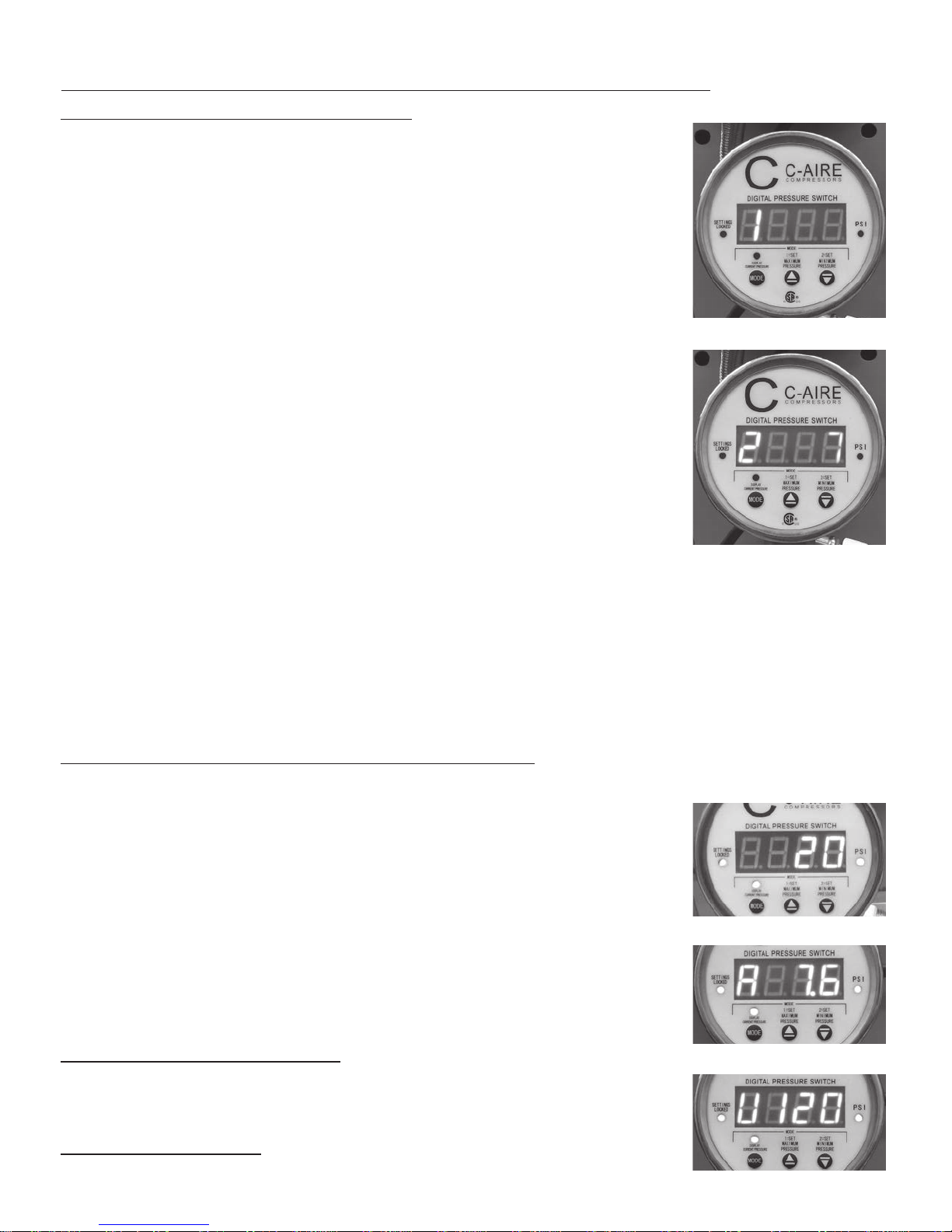
DIGITAL PRESSURE SWITCH PROGRAMMING AND INSTRUCTIONS
When the air compressor is first powered on, PSI light is illuminated, press the “MODE button.
SCREEN DISPLAY/SETTING PRESSURE
Use these three buttons to set maximum and minimum pressure:
A. MODE B. UP ARROW C. DOWN ARROW
STEP 1:
Press the “MODE” button once, the number “1” will display on the screen. You can now set the maximum pressure you would
like using the “UP ARROW” button or “DOWN ARROW” button. (with precision to 0.1 psi). The maximum pressure is
displayed on the screen. The setting range is: 10-90psi.
STEP 2:
Press the “MODE” button again, the number “2” will display on the screen. You can now set the minimum pressure you
would like using the “UP ARROW” button or “DOWN ARROW” button. (with precision to 0.1 psi). The minimum pressure is
displayed on the screen. The setting range is: 5-85psi.
There is a 5° differential on the settings so if you would like to change maximum/minimum pressure settings, change the
low or minimum pressure setting first and then set the high or maximum pressure. Otherwise the 5° differential will not
allow you to change the pressure settings.
EXAMPLE:
The maximum pressure setting is set at 12psi and the minimum pressure is set at 7psi. You wish to change the maximum
pressure to 10 and minimum pressure to 5. Press the mode button until you see the minimum pressure of 7 on the screen.
Change the setting to 5 using “DOWN ARROW” button. Next press the “MODE” button once again to see the maximum
pressure of 12 on the screen. Use the “DOWN ARROW” button to change the setting to 10. If you try to set the maximum
pressure first the digital pressure switch will not allow you to change the number to 10 because that would cause the drop
to be below the 5° differential.
1. SCREEN DISPLAY/OPERATION
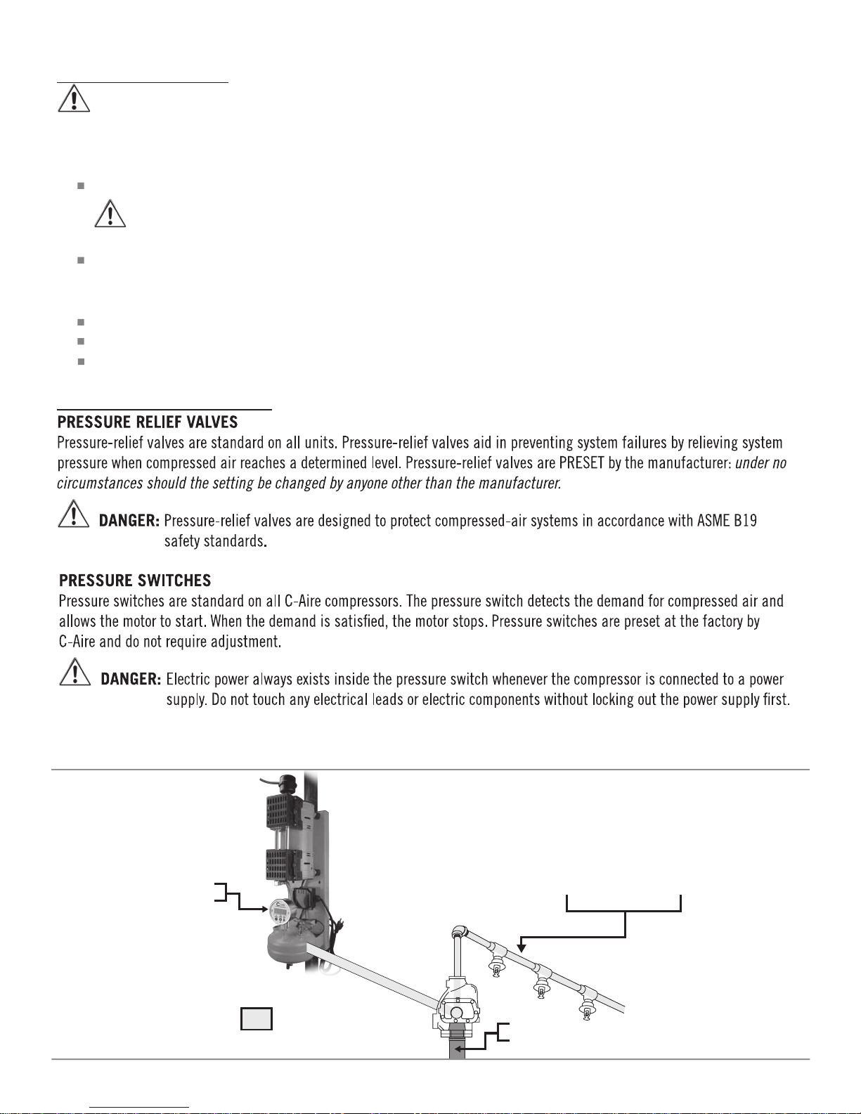
INLET AND DISCHARGE PIPING
CAUTION: Do not operate unit without inlet-air filtration.
If the air is dirty, pipe the filter to a source of clean air.
Do not install piping with a diameter lower than that of the pump intake.
CAUTION: Do not use PVC plastic in the discharge line.
Use hand-welded or threaded steel or copper pipes and cast-iron fittings that are safe for the discharge pressure and
temperature.
WARNING: Compressor installation must be performed by a qualified electrician in accordance with the National
Electrical Code (NEC) or the Canadian Electrical Code (CEC), the National Electrical Safety Code (NESC)
OSHA code, and/or any local or state codes having precedence.
Be sure of proper wire sizing and that the circuit breaker and the distance from the breaker is within suggested range.
Confirm your electrical-supply voltage matches what is required for the motor.
WARNING: The compressor must be grounded. Grounding reduces the risk of electric shock. Certain C-Aire models
are equipped with a cord that has a grounding wire with a grounding plug. The plug must be plugged
into an outlet that is installed and grounded in accordance with all local codes and ordinances.
WARNING: Improper installation of the grounding plug will result in a risk of electric shock. When repair or
replacement of the cord or plug is required, do not connect the grounding wire to either flat-blade
terminal. The insulated wire with a green outer surface and yellow stripes is the grounding wire.
NOTE:
The installation, electric motor, wiring, and all electrical controls must be in accordance with NFPA 70-1996 National
Electric Code, National Electric Safety Code, and state and local codes.
Failure to abide by the national, state, and local codes
may result in physical harm and/or property damage.
DANGER: High voltage may cause personal injury or death. Disconnect and lockout/tagout, per OSHA regulation
1910.147, all electrical power supplies before opening the electrical enclosure or servicing.
DANGER: Never assume a compressor
is safe to work on if it is
not operating. It could
restart at any time.
Always disconnect/
lockout/tagout
before servicing.
CAUTION: Dry pipe sprinkler
compressor must be
wired to a reliable
power source to be
compliant with
NFPA 13.
RED
BLACK
WHITE
BROWN
BLACK
WHITE
BLACK
WHITE
BLACK
WHITE
WIRE
COLOR
CODE