2
SPECIFIC SAFETY RULES
PIPE STAND
WARNING
Read all safety warnings and all
instructions provided with the pipe
•
•Properly assemble the pipe stand before use.
Proper assembly is important to prevent risk of
collapse.
stand and any power tools to be used with the
stand. Failure to follow the warnings and instruc-
tions may result in electric shock,fire and/or
serious injury. Save all warnings and instructions
for future reference.
•
•
•
•
•
•
Place the pipe stand on a solid, flat and level
surface. When the pipe stand can shift or rock,
the power tool or workpiece cannot be steadily and
safely controlled.
When collapsed, place stand on it's side or secure
before leaving unattended. Leaving the collapsed
stand vertically may cause the stand to tip over.
Do not overload the pipe stand or use as ladder
or scaffolding.Overloading or standing on the
pipe stand causes the stand to be “top-heavy” and
likely to tip over.
Keep work area clean and well lit. Cluttered, dark
work areas invite accidents.
Maintain control. Keep proper footing and balance
at all times.
•Do not overreach. Keep proper footing and
balance at all times. This enables better control
of the power tool in unexpected situations.
•Avoid dangerous environments. Use the pipe
stand on flat, level, dry, and hard surfaces only.
•
•
•
Maintain pipe stand carefully. Keep pipe stand
dry, clean and free from oil and grease. Follow
instructions for changing accessories. Periodically
inspect pipe stand for damage and wear.
Keep bystanders away. Children and bystanders
should be kept at a safe distance from the work area
to avoid distracting the operator.
•
To reduce the risk of injury, always wear eye
protection.
Inspect the pipe stand and screws periodically
and replace immediately if cracked, worn, or
damaged. Do not attempt to fix or mend damaged
pipe stand or fasteners.
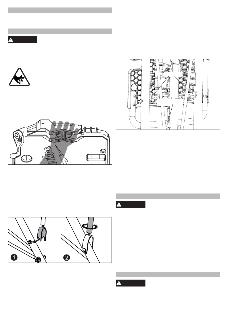
Fingers can be pinched between the legs and
the underside of the tabletop. To reduce the risk
of injury, keep fingers out of the areas where the
legs will secure into place.
•
•
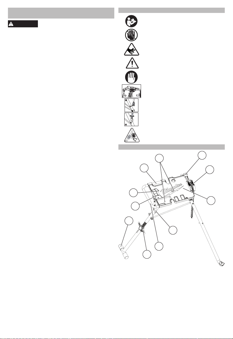
FUNCTIONAL DESCRIPTION
SYMBOLOGY
Read Operator's Manual
No hands zone
Crush hands
Safety alert symbol
Place hand here
Hand grip
Attach turnbuckle
Twist turnbuckle to tighten
Pinching fingers hazard
2
3
45
6
8
11
7
1
9
10
1. Pipe secondary support
2. Leg locking fold latch
3. Carry handle
4. Oil drain holes
5. Chain tightening handle
6. Chain vice
7. Workspace tabletop
8. Turnbuckle
9. Rear handle
10.Level adjuster
11. T-bar foot
Maintain labels. These carry important
information. If unreadable or missing, contact a
MILWAUKEE®service facility for a replacement.
Dress properly. Do not wear loose clothing or
jewellery. Keep your hair and clothing away
from moving parts. Loose clothes, jewellery or
long hair can be caught in moving parts.
Always use common sense and be cautious
when using tools. It is not possible to anticipate
every situation that could result in a dangerous
outcome. Do not use this tool if you do not
understand these operating instructions or you
feel the work is beyond your capability; contact
MILWAUKEE®Tool or a trained professional for
additional information or training.