MIMAKI TX-Y6018P User manual

TX-Y6018P POWDER SHAKER
User Manual
2020.06

FOREWARD.................................................................................................................... 3
About The Manual................................................................................................ 3
1. Safety Operating Instructionrs ................................................................................... 4
Brief Introduction.................................................................................................. 4
Safety Symbols.................................................................................................... 4
Warning and Precaution for Use.......................................................................... 4
Installation Precautions........................................................................................ 5
2. Install Preperation ...................................................................................................... 6
MachineSpecications........................................................................................6
Operating Conditions........................................................................................... 6
Electrical connecton requirements....................................................................... 7
3. Installation .................................................................................................................. 8
Unpack box ......................................................................................................... 8
Connect Power .................................................................................................... 8
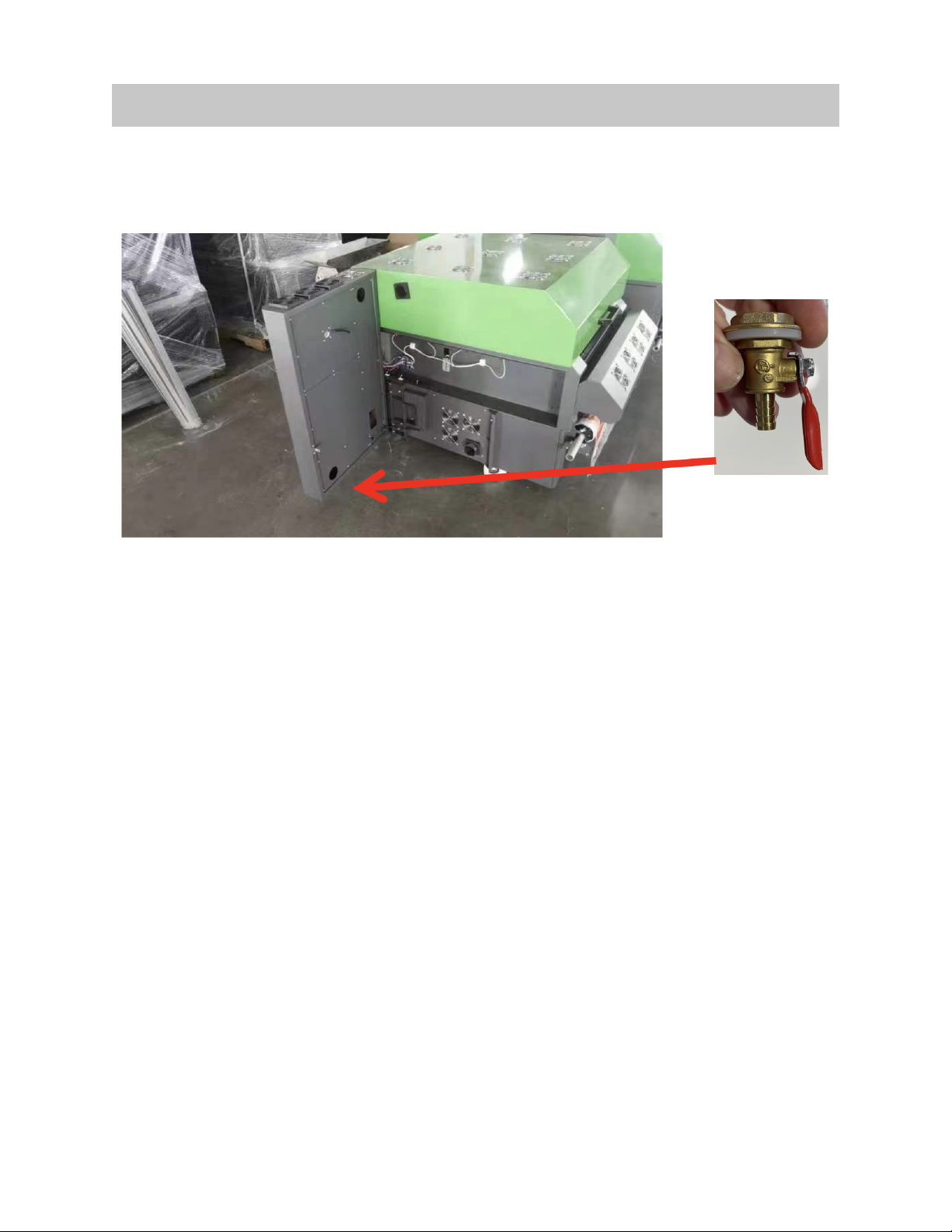
Installvalveundertheltration............................................................................9
4. Names of Parts and Functions ................................................................................. 10
Front of the Machine ......................................................................................... 10
Back of the Machine .......................................................................................... 12
Electrical Box ..................................................................................................... 13
5. Basic Operation ........................................................................................................ 14
Setting the Film.................................................................................................. 14
Main Panel Interface ........................................................................................ 15
Parameter Panel Interface ..................................................................................16
Trouble Shooting ............................................................................................... 17
7. Maintenance ............................................................................................................ 18
Appendix
Appendix1:2-WayDriveBoardInformaition....................................................19
Appendix 2: 5-Way Drive Board Informaition .................................................... 20
Appendix 3: 4-Way Drive Board Informaition .................................................... 21
Appendix 4: PLC Information ........................................................................... 22
Table of Contents

FOREWARD
Congratulations on your purchase of TX-Y6018P Powder Shaker. Be sure to read this
Operation Manual carefully and fully understand it before using the machine. Also,
always keep this Operation Manual at hand and use it.
About The Manual
• This Operation Manual explains how to install, operate, maintain TX-Y6018P
powder shaker.
• Be sure to read this Operation Manual and fully understand how to
operate the machine safely and properly before using the machine. Also,
always keep this Operation Manual at hand and use it. Please arrange to
deliverthisOperationManualtoastamemberwhousesthismachine.
• AlthoughthisOperationManualhasbeencarefullypreparedforyoureasy
understanding, please do not hesitate to contact your local distributor if you have
any inquiry.
• ThecontentsofthisOperationManualaresubjecttochangesforimprovement
without notice. Please be advised.
• IfyoucannotreadthisOperationManualbecauseofburningordamage,please
obtain a new Operation Manual from your local distributor or sales representative.
• YoucanalsodownloadthelatestversionoftheManualfromourwebsite.
3

1. Safety Operating Instructions
This caution symbol represents danger. Failure to observe the instructions
givenwiththissymbolcanleadtoseriousinjurytopersonnelanddamage
to the machine.
This Chapter introduces the important safety information. Please read and understand
the safety information carefully before operating the machine.
1.1 Brief Introduction
1.3 Warning and Precaution for Use
1.2 Safety Symbols
• The vacuum exhaust system must be functioning before the machine operates.
• Donotignorethissafetywarningprecautiontoavoidaccumulationofammable
fumes in the area.
Proper Ventilation and Exhaust System
• Openames,heatenergyorsparkaroundthemachinecantriggerreand
explosion.
• Nosmoking,pilotlights,openames,stoves,heaters,orhalogenlightsshouldbe
turn on within 5m distance from any edge of the machine.
• No portable spark-producing equipment (static, electrical, or mechanical) within 5
meter distance from any edge of the machine.
Danger of Fire and Explosion
• If there is no emergency power switch which can shut down all the power, do not
connect the machine to main-power supply.
• When the machine’s power is on, do not open the right door of the machine, or
avoid touching electrical parts.
High Voltage Precaution to Avoid Personnel Shock or Fire
4

1.3 Warning and Precaution for Use Continued
• The machine should be grounded, according to the local safety electrical
connection regulation. The ground voltage should be less than 3V.
• Setthemachineonsmoothatceramictileorceramicground.
• Usespeciedanti-staticoormattominimizeharmfulstaticbuild-up.
• Be careful not to damage, break or modify the power cable. Also do not place
anyheavyobjecton,heat,orpullthepowercable.Doingsocancausepowercable
breakage,resultinginreorelectricshock.
• Usethismachinewiththeindicatedpowerspecications:AC220V,50/60Hz
• Avoid damp locations when using this machine. Do not splash water onto this
machine.Itmaycausere,electricshockormalfunctionofthismachine.
• Useofthemachinewhenitissueringsomeproblemindicatedbytheemittance
ofsmokeorunpleasantsmellcanresultinreorelectricshock.Besuretoturno
thepowerswitchimmediatelyanddetachtheplugfromtheoutlet.Checkrsttobe
sure that the machine no longer produces smoke, and contact your local distributor
for repair. Repair by customers is dangerous so please never do it.
• Never disassemble or modify this machine. Disassembling or modifying either will
result in electric shock or malfunction of this machine.
• Keepngersandotherbodypartsawayfromhazardousmovingparts.
High Voltage Precaution to Avoid Personnel Shock or Fire
1.4 Installation Precaution
• Install the machine near an easily accessible electrical outlet.
• Do not provide power to the machine through the same power line as for other
noise generating devices such as motors.
• Connect the power cable directly to an electrical outlet. Use independent power
source.
Power Supply
• Do not place anything on the top of the machine.
• Do not lean body against or rest elbows on the machine.
• Open and close the top cover gently from the front of the machine with both hands.
• Before connecting or disconnecting the interface connector, turn the machine OFF.
Machine Handling
5

2. Install Preperation
2.1 Machine Specication
• Machine requires forklift to remove from box.
• Do not place anything on the installation site, and make sure that
people do not approach the installation place. It may cause damage
tothemachineorpersonnelinjury.
Model: TX-Y6018P
Environment: Temperature:18-30℃(65-86ºF)
Humidity:30-70%RH
Power Consumption: Working mode: 5000W
Power Supply: AC220V,50/60Hz
Dimension(L*W*H): 76” x 45” x 45” inch
Weight: 750 lbs.
2.2 Operating Conditions
Installation Space and Mechanical Requirements:
• Unload Space:Thespacemustbetwotimesofthebox’ssize,fortheconvenient
of unload and unpack.
• Required Equipment: Forklift (Bearing capacity referring to the weight of the
machine. The length of the fork must be 15cm longer than the width of the box).
• Installation Space:Sucientspacearoundthemachinetoaccessfrequentlyused
parts.
• Operating Environment Conditions:Temperature:18-30℃(65-86ºF)andrelative
humidity:30-70%
This is a pre-install guide for Y6018P Powder Shaker. Customers are recommended
to prepare the room and other necessary devices before the machine arrives for
installation.
6

• Alocationnearare
• Places exposed to direct sunlight
• Placessubjecttovibration
• Placessubjecttoextremechangesintemperatureorhumidity
• Places near an air conditioner or a heater
• Places where the machine may get wet
• Placesnearadiazocopierthatmaygenerateammoniagas
• Places with poor ventilation
• Unstable location
Do Not Install the Machine in the Following Places:
2.3 Electrical Connection Requirements
PowerSpecication:
Rated Voltage: 220VAC(±5%)
Rated currency: 40A
Input power frequency: 50/60HZ
Phase: Single-phase
• The machine should be grounded, according to the local safety
electrical regulation.
• The grounding should be less than 3V.
• Usespeciedanti-staticoormattingtominimizeharmfulstaticbuild
up.
• Use ESD Ground Strap when handing any Electric Boards to avoid any
electric static discharge that may damage these parts.
• Do not open the cover where electrical spare parts are located to avoid
possible electrical shock.
Electrical Safety:
7

3. Installation
Machine comes in wooden box (crate).
1. Unpackthecrateandplace4pcswooden/metalblacksunderthewheelstoliftthe
machine from the base.
2. Lift the machine from the gap between machine and base. Place in install space.
3.1 Unpack Box
3.2 Connect Power
1. Using electrical cable that came with the machine. Please connect to the machine
one side and another side to the power.
2. Lifttheplatefromrightsideofthemachine,connectthejunctiontothe110Voutput
port of the transformer using the attached spare wires. Transformer input port
connet to 220v power like photos.
NOTE: The machine must be well grounded.
8

8
NOTE: The machine must be well grounded.

3.3. Where to Install the Valve
1. Find the valve from the powder tray and install it into the hole that’s under the
ltration.
9

4. Names of Parts and Functions
4.1 Front of the Machine
1. Emergency stop switch.
2. Main power switch.
3. Powder spray box.
4. Media sensor (Belt move forward
whenlmisdetected)
5. Preheating plate
6. Cooling fans
7. Powder preheating lamp (inside)
10

4.2 Powder Applicator and Shaker
8. Intelligent powder control system (Powder spray motor
stop working when the powder reaches a certain weight)
9. Powdershakebar.
10.Rear feeding cylinder with vacuum
11

4.3 Back of the Machine
11. Vented oven lid
12. Heatinglamp
13. Mesh belt vacuum and heating system
14. Front feeding cylinder with vacuum
15. Additionalvacuumplate(Preventlmdropping)
16. Tension take up system
17. Material Cooling fans
18. Zoneltrationdevice
19. CharcoalandHEPAltrationcore
20. Machine cooling fans
21. Powder recycle tray
12

4.4 Electrical Box
1. 110v main power inlet
2. AC contactor
3. Power supply
4. PLC controller
5. Heatingcontroller
6. Sensor and motor driver board
7. Motor driver board
13

5. Basic Operation
Turnonthemachineandloadthelmaccordingtobelowdiagram:
5.1 Setting the Film
•Once the printer has printed enough transfers to cover the front preheating board
andthemediaextendstotherstoftwovacuumcylindersensurethatthePET
transfer media is aligned correctly to inhibit any skew that may be present through
the heating tunnel and take-up reel.
•Whenthemediaisplacedcorrectlytotherstvacuumcylindertheshakersuction
system should be in the on position. From this point the media will now be
controlled by both the vacuum and mesh belt system through the heating tunnel.
It is important to notice that when placing the media under the powder hopper for
thersttimethatenoughslackisprovidedtoallowpowdertollatthebottomand
thenbeshakenoasthemediamovesbackupthroughthebeltsystem.
• Afternishingthecurrentprintjob,cutthelastpartofPETmediaandenterthe
print linkage mode.
•Thelmwillthenbeautomaticallywoundbythetake-uptocompletetheprinting
process.
14

5.2 Main Panel Interface
15

5.3 Parameter Panel Interface
16

5.3 Parameter Panel Interface Settings
17

5.4 Trouble Shooting
IO to check working condition of machine.
18

I. How to Set Powder Dusng Parameter
1. Principle of Powder Dusng Parameter:
i. In the seng page. There is feed sensor para.
ii. Value – Current height value of the powder box posion.
iii. Up: height value when powder box doesn’t have enough powder. It will
acvate the powder dusng funcon to work.
iv. Down: low value when powder box is in low posion which means there
is enough powder. It will stop the dusng funcon.
II. How to Set Powder Dusng Parameters and Check Working Properly
1. Li the powder box up and hold the set buon of the UP parameter for 3 secs.
i. It will record the posion of the empty box.
2. Push the powder box to the boom, then li a lile bit from the boom and hold
set buon of down parameter. Value for low posion is recorded for the low
posion which means there is enough powder in the box.
3. To test dusng funcon: Li and push down the powder box to check if dusng
funcon is working properly.
5.4 Trouble Shooting - Check/Set Powder Dusting Function
19
Table of contents