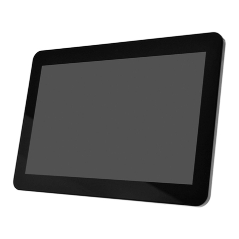
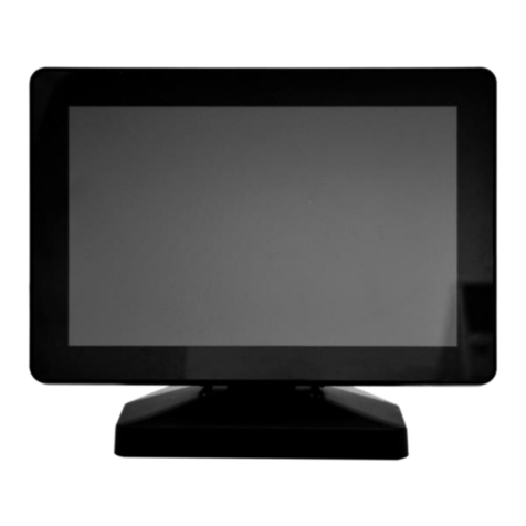
Mimo Monitors MY-1090CV User manual

Ver 0.1 (6/21) PAGE 2 OF 30 ©Mimo Monitors
Contents
▣Safety Instructions..........................................................................................................................3
▣Product Features ............................................................................................................................5
Product Specifications & Features................................................................................................6
System Requirements.....................................................................................................................7
Package Contents...............................................................................................................................8
▣ Connections and Installation.......................................................................................................10
Basic Concept –Point to Point with CAT5e in Conference space.........................................10
Second Concept –Using existing CAT5e to create a Point to Point connection in
Conference space..........................................................................................................................13
Third Concept –Using existing CAT5e to create a Point to Point connection in
Conference space..........................................................................................................................14
Fourth Concept –Using existing CAT5e to create a networked connection in Conference
space................................................................................................................................................16
Fifth Concept –Using existing CAT5e to create a shared networked connection in
Conference space with VLANs....................................................................................................17
▣Display Setting ..............................................................................................................................19
▣Tablet PC Settings for the use of Capacitive Touchscreen...................................................20
▣Troubleshooting............................................................................................................................22
▣Appendix 1: Myst Link FAQs.......................................................................................................24
▣Appendix 2: Installing DisplayLink Monitor Driver...................................................................27
[ Windows 10 operating systems ] ..............................................................................................27

Ver 0.1 (6/21) PAGE 3 OF 30 ©Mimo Monitors
▣Safety Instructions
These safety instructions must be followed to ensure your safety and prevent property
damage.
Warning/Cautions:
Otherwise, it may result in personal injury or property damage.
Make sure to read the instructions carefully and use the product in the correct manner.
▪Power Source:
- Link accepts 12V/3A power supply included in the
box. Other 12V/3A AC/DC adapters may work, but
have not been tested.
- Myst display uses either the included Link or
802.3af compliant PoE power.
* Monitor does not accept any other power
source
▪Do not place Monitor in a location exposed to
moisture, excessive dust, smoke, or water.
* Otherwise, this may result in electric
shock or fire.
▪Clean the product using a soft cloth with a
monitor cleaner only.
- It is best to disconnect power while cleaning
- Ensure that cleaner or other liquid does not
enter the product and that it is not wet.
▪Do not apply force to LCD (Touch Panel)
Screen
- Do not tap or scratch LCD (Touch Panel)
Screen with a sharp object.
- Do not press with excessive force with any
object
* Otherwise, LCD (Touch Panel) may be
damaged.

Ver 0.1 (6/21) PAGE 4 OF 30 ©Mimo Monitors
▪Product Input/Output Connectors
- Do not insert anything other than the proper
cable into the connectors
- If foreign material enters the product,
disconnect the Ethernet cable and contact a
Service Center.
▪Do not install Monitor in an unstable location
- Otherwise, it may fall and cause personal
injury and/or damage the product.
▪There are no user serviceable components or
preventative maintenance.
- Do not disassemble, repair or modify the
product
- If the product needs to be repaired, contact a
Service Center.
If water enters the product, disconnect the Ethernet cable and contact a
Service Center. This may result in a product malfunction, electric shock, or
fire.

Ver 0.1 (6/21) PAGE 5 OF 30 ©Mimo Monitors
▣Product Features
Designed with today’s modern conference room in mind, the 10.1” Mimo Myst Link features
easy-to-use Ethernet connectivity, which simplifies installation and eliminates the hassle of
abundant and expensive cords. Distances up to 100m are directly supported. Beyond 100m
is still possible when running across a switched network.
This innovative conference room solution is recognized by PCs as a regular display,
maximizing usable space and productivity, without increasing complexity and IT
requirements. Due to its ubiquitous cabling, which also supplies power (no power at the
table needed!), it is seamless for IT to set up and simple to maintain, cutting long-term costs
and the need for technical know-how. It also allows for long distance installations, paving
the way for flexible and moveable furniture configurations, necessary for today’s evolving
work environment. In addition, the capacitive touch display provides a USB connection
through to the host computer for connecting hardware such as a speaker/mic without
requiring any additional extenders or cables.
▶AV-over-IP connected 1280x800 touch display that is recognized by PCs as a
regular display
▶2-piece solution (Display at the table and box at the PC, connected via CAT5e
cable)
▶Compatible with Windows 8 (and higher), Linux, Chrome, and Mac OS*
▶Integrated HDMI Capture up to 1080p in standard UVC and UAC protocol for wide
software support
▶Can transmit 4k video from display side to PC side
▶USB input to optionally USB accessories such as a speaker/mic
▶POE Injector built into Link box provides stable power to the monitor.
Ver 0.1 (6/21) PAGE 6 OF 30 ©Mimo Monitors
Product Specifications & Features
ETHERNET
Ethernet Interface
RJ45
Input Interface
Cat5a Ethernet cable
Supported Bandwidth
Gigabit Ethernet
1000
CAPTURE
SECTION
Video
USB Video Class (UVC)
Audio
USB Audio Class (UAC)
Resolution
Up to 1080p captured
Link HDMI Resolution
Up to 4k/30 from Myst to
Link at HDMI connector
DISPLAY
SECTION
Video
AV over IP
Touch
USB Over IP (HID Compliant)
10 point touch
PCAP
Contrast
1000:1
Size
10.1”
Luminance
360
cd/㎡
Resolution
1280x800
Active Area
216.96 mm(W) x 135.60 mm(H)
Pixel Pitch
0.1695 mm(W) x 0.1695 mm(H)
Number of LCD Colors
up to 16.7M
Viewing Angle
89/89/89/89
U/D/L/R
FEATURES
Human Presence Sensor
Yes. IR.
3m at +/- 90 degrees
Other Sensors
- Ambient Light
- Orientation
- Temperature (2x)
HID Sensor
Compliant
Stereo Audio
200 Hz-20 kHz, 1W max
Headset
Stereo with mic and jack
detect
Mounting
Wall mountable with
custom bracket
Cable channels
For strain relief with
locking plate
Security Slot
Kensington lock port

Ver 0.1 (6/21) PAGE 7 OF 30 ©Mimo Monitors
Color
Gray
MY-1090CV
Plug and Play
Yes
Up/Down Scaling
Yes
Firmware Upgradeable
Yes
Operating Temperature
-10 to 40
C
Storage Temp
-20 to 60
C
External Power (Link)
12V/3A AC/DC Adapter
External Power (Myst)
PoE 802.3af compliant
Supplied by Link
Power Consumption
16.0
W(max w/o USB
accessory)
Dimensions
247(W) x 151(D) x 102(H)
Retail Box
290mm(W) x 195mm(D)
x 130mm(H)
Weight (Display)
0.99 kg
Weight (Box)
1.9 kg
CERTIFICATIONS
FCC, UL, CE, RoHS, RCM
System Requirements
• CPU: Intel Pentium/Celeron/AMD/K6/Athlon/Duron 1.2GHz or above.
• RAM: 512MB RAM or above.
• USB: at least one USB3.0 port.
• HDD: 50MB HDD space above.
• O/S: Windows 10 (32/64 bit) or later, Chrome, Linux, or Max (limited Support)

Ver 0.1 (6/21) PAGE 8 OF 30 ©Mimo Monitors
Package Contents
Please make sure the following items are included with your monitor.
Contact a local dealer to buy optional items.
▶MY-1090CV-M
▶MY-1090CV-L

Ver 0.1 (6/21) PAGE 9 OF 30 ©Mimo Monitors
Cat5e Ethernet Cable (color varies) HDMI Cable
AC/DC Adapter USB3.0 Cable
※Please contact your local dealer if any items are missing in the package
contents.

Ver 0.1 (6/21) PAGE 10 OF 30 ©Mimo Monitors
▣ Connections and Installation
Recommended Installation Method –Point to Point with
CAT5e in Conference space
This installation method will require one new cable to be laid, point to point between the 2 boxes.
Myst display and Link will not be on the network. No other wired network devices may share the
cabling.
Requirements
- The run from the Myst Display to Link is less than 100m
Installation Concept
Figure 1: There is a dedicated CAT5e cable from Myst Display to Link PC with camera (not
supplied) and Link
shown installed
generally behind the
big screen in a typical
conference room
The green wire
represents the Cat5e
cable between the
Myst and Link
The Myst sits on the
conference table,
along with, optionally,
a USB speaker/mic
connected through the
Myst

Ver 0.1 (6/21) PAGE 11 OF 30 ©Mimo Monitors
Network Setup
Have AV or IT personnel run a dedicated CAT5e cable from Link/PC side to Myst display/table side.
Link Setup
To setup the Link part you will need the following:
•Power Cable –Included in box
•Usb 3.0 A to B cable –Included in box
•HDMI cable (optional) –Not included
•Cat 5e cable –5m cable included. If a different length is desired, any Cat5e compliant cable
is acceptable
1. Place the Link near a host PC.
2. Plug the USB cable B side into the Link and the A side into the host PC. Be sure that the
PC is connected to the internet and that automatic driver install is enabled. While no
drivers are needed to be manually installed, some drivers are part of the Windows Online
Driver store, and will need to be downloaded.
3. Connect the Cat 5e cable to the Link (See Connection Options Section)
4. Optional –Connect the HDMI cable to the Link and the other end to the screen in the room.
This allows for table to screen output
5. Configure the Link’s DIP switch to match the Myst’s DIP switch. The setting does not matter,
so long as it is the same on both sides
6. Connect the power cable to AC power using the proper blade adapter for your country. The
Link will turn on.
7. If the Green light on the RJ45 input is on, that means the Myst and Link are connected

Ver 0.1 (6/21) PAGE 12 OF 30 ©Mimo Monitors
Myst Setup:
To setup the Myst you will need the following:
•Cat 5e cable (from above)
•HDMI cable for HDMI capture function (optional) –Included in box
•USB-C to proper USB connection adapter, if necessary, if you wish to connect a USB
device, such as a speaker/mic through the Myst. This device will show up at the PC as if it
were directly connected
1. Place the Myst on a conference room table or anywhere desired for easy accessibility
2. Configure the Myst’s DIP switch to match the Link’s DIP switch
3. Optional –Connect the HDMI cable to the Myst if the HDMI capture functionality is planned
4. The Myst does not require connecting a power adapter as power is supplied over PoE from
the Link. If connecting through a switch or other network infrastructure make sure PoE is
injected over the Cat 5e cable supplying power to the Myst
5. If the Green light on the RJ45 input is on, that means the Myst and Link are connected
6. The Myst’s display should come on within 15 seconds of connecting the Link’s USB cable to
a online PC. If after 60 seconds, the screen does not turn on, please remove the RJ-45 from
the Myst and re-insert to power cycle the system. This should only be required on the first
installation.
7. When using the touchscreen on the Myst, if the touch is being seen on another display, go
into Windows Control Panel Tablet PC settings to configure the touch to be seen on the Myst
display. See section “Tablet PC Settings for the use of Capacitive Touchscreen” later in this
document

Ver 0.1 (6/21) PAGE 13 OF 30 ©Mimo Monitors
Second Concept –Using existing CAT5e to create a
Point to Point connection in Conference space
This installation method will not require new cabling to be laid, but will consume the existing cabling
and the Myst and Link will not be on the network. No other wired network devices may share the
cabling.
Requirements
- This installation assumes that there is an existing Network connection near the Myst and the
Link
- The run from the network termination point (IT closet) is less than 50m
- This concept is extensible to as many Myst/Link pairs as exist in the closet without limit.
Installation Concept
Same as figure 1, except rather than a dedicated wire through the conference room, you connect
them together back in IT closet
Myst Display and Link Wrapped back to each other
Figure 2:
Network Setup
Find where the Myst Display and Link terminate in local IT closet using network tone and probe tool,
or other method. Remove connection from patch panel to network in both locations. Install new
cable between the 2 termination points. Proceed with setup identical to “Basic Concept”

Ver 0.1 (6/21) PAGE 14 OF 30 ©Mimo Monitors
Third Concept –Using existing CAT5e to create a Point
to Point connection in Conference space
This installation method will not require new cabling to be laid, but will consume the existing cabling
and the Myst and Link will not be on the network. No other wired network devices may share the
cabling.
Requirements
- This installation assumes that there is an existing Network connection near the Myst and the
Link
- The run from the network termination point (IT closet) is less than 100m
- This concept is extensible to up to as many Myst/Link pairs in the IT closet as required. No
more than 16 pairs per PoE switch are allowed.
- The PoE switch chosen can support 15.6W (802.3af) per port that a Myst display is
connected
Installation Concept
Same as figure 1, except rather than a dedicated wire through the conference room, you connect
them together back in IT closet. The data is re-created with a dedicated PoE capable network
switch, but that switch is not on the corporate AV or IT networks
Myst Display and Link Wrapped put on Non-networked PoE Ethernet Switch
Figure 3:

Ver 0.1 (6/21) PAGE 15 OF 30 ©Mimo Monitors
Network Setup
Find where the Myst Display and Link terminate in local IT closet using network tone and probe tool,
or other method. Remove connection from patch panel to network in both locations. Install new
cable those points and a PoE switch. This PoE switch is ‘stand-alone’ and IS NOT connected to the
corporate IT or AV networks. Proceed with setup similar to “Basic Concept” with the following
exceptions
- Link Step 5: Configure the Link’s DIP switch to match the Myst’s DIP switch. The setting
matters, and must be unique for each pair that are sharing a PoE switch. Up to 16 units may
share a switch
- Myst Step 4: The Myst does not require connecting a power adapter as power is supplied
over PoE from the switch. Be sure that the switch used is capable of powering 802.3af from
each port connected to the Myst display.

Ver 0.1 (6/21) PAGE 16 OF 30 ©Mimo Monitors
Fourth Concept –Using existing CAT5e to create a
networked connection in Conference space
This installation method will not require new cabling to be laid, but will consume the existing cabling
and the Myst and Link will be on the network. Other wired devices may share the same network
infrastructure backbone.
Requirements
- This installation assumes that there is an existing Network connection near the Myst and the
Link
- The run from the network termination point (IT closet) is less than 100m
- This concept is extensible to up to as many Myst/Link pairs on the corporate AV or IT as
required. No more than 16 pairs per Lan are allowed. Beyond 16, VLANs are required (See
5th concept)
- The PoE switch chosen can support 15.6W (802.3af) per port that a Myst display is
connected
- Network security measures such as 802.1x are MAC address based
- Network backbone can support Gigabit switching without blocking. During an active HDMI
capture, each Myst/Link pair will generate in excess of 800 Mbit/s of data.
Installation Concept
The Myst display and Link are on the corporate AV or IT network
Network Setup
Connect Myst display and Link to Ethernet ports that are connected to the corporate network.
Proceed with setup similar to “Basic Concept” with the following exceptions
- Link Step 5: Configure the Link’s DIP switch to match the Myst’s DIP switch. The setting
matters, and only 16 Myst/Link pairs are allowed per VLAN
- Myst Step 4: The Myst does not require connecting a power adapter as power is supplied
over PoE from the switch. Be sure that the switch used is capable of powering 802.3af from
each port connected to the Myst display.

Ver 0.1 (6/21) PAGE 17 OF 30 ©Mimo Monitors
Fifth Concept –Using existing CAT5e to create a shared
networked connection in Conference space with VLANs
This installation method will not require new cabling to be laid but will consume the existing cabling
and the Myst and Link will be on the network. Other wired devices may share the same network
infrastructure backbone. VLANs are used to allow for any number of Myst/Link pairs to be installed
as well as for Network security
Requirements
- This installation assumes that there is an existing Network connection near the Myst and the
Link
- The run from the network termination point (IT closet) is less than 100m
- This concept is extensible to up to as many Myst/Link pairs on the corporate AV or IT as
required. No more than 16 pairs per Lan are allowed. VLANs allow for (virtually) unlimited
pairs installed
- The PoE switch chosen can support 15.6W (802.3af) per port that a Myst display is
connected
- Network security measures such as 802.1x are MAC address based
- Network backbone can support Gigabit switching without blocking. During an active HDMI
capture, each Myst/Link pair will generate in excess of 800 Mbit/s of data.
- ‘Other’ network traffic over the ‘Link’ connection, during an HDMI capture must be less than
100 MBIT/S, or packet congestion and loss will occur, resulting in unexpected performance
Installation Concept
The Myst display and Link are on the corporate AV or IT network utilizing VLANs for security and to
increase the number of devices allowed. A local intelligent Ethernet switch is utilized in the
conference room, generally where the PC resides to keep network traffic isolated.
As shown in figure 1 but includes an intelligent switch behind the big screen connected as such.

Ver 0.1 (6/21) PAGE 18 OF 30 ©Mimo Monitors
Link Device Connection to Other Connection to
Using unique VLAN in-room PC Devices Corporate Network
0-4094 (no or different VLAN) as needed
Network Setup
For this example, a direct connection between the Myst display and the corporate network is
assumed, but the described concept used on the Link can be utilized on the Connect Myst display
to corporate network and program that port via the smart switch, on a port basis to only support one
VLAN ID (for this example, VLAN 1000). Connect the Link to the Ethernet port on the smaller in-
room switch, and program port 1 to VLAN 1000). The other ports may or may not use VLANs as
utilized within the corporate IT system. Up to 16 pairs of Myst/Link devices may share VLAN 1000
before a different VLAN must be used. that are connected to the corporate network. This isolates
network traffic between the Link and the Myst display. Proceed with setup similar to “Basic Concept”
with the following exceptions
- Link Step 5: Configure the Link’s DIP switch to match the Myst’s DIP switch. The setting
matters, and only 16 Myst/Link pairs are allowed per VLAN
- Myst Step 4: The Myst does not require connecting a power adapter as power is supplied
over PoE from the switch. Be sure that the switch used is capable of powering 802.3af from
each port connected to the Myst display.

Ver 0.1 (6/21) PAGE 19 OF 30 ©Mimo Monitors
▣Display Setting
[ Windows 10 –Controlling the MY-1090CV Display ]
1. MIMO Myst Network Display Properties Setting
You can configure the Mimo Myst Display device through the use of Windows Display
Properties (WDP), which provides a simple method to attach, rotate, duplicate or extend
screens as well as modify screen resolution.
1. Open Windows Display Properties (WDP)
2. Set the display options, refer to the table below for details on each option
*. How to open Windows Display Propertied (WDP)
1. Right-click on the desktop
2. Select Screen Resolution from menu

Ver 0.1 (6/21) PAGE 20 OF 30 ©Mimo Monitors
▣Tablet PC Settings for the use of Capacitive Touchscreen
This section shows you how to set the “Tablet PC Settings”to use the capacitive
touchscreen for Multi-touch use on Windows 10
1. Tablet PC Settings
2. Identifying your device as the touchscreen
Touchscreen identification screens will open according to the configuration procedures
and instructions as below
①Touch the screen to identify it as your touchscreen and press ‘Enter’ to move the next
screen if is not the “Tablet PC Screen”.
②Press ‘Enter’ to proceed to the next step to complete the configuration after you a
touchscreen is identified as your touchscreen.
③Press ‘Esc’ whenever you want to close this identifying tool.
①Select Control Panel / Hardware and Sound
②And Click the “Setup” on the “Tablet PC
Settings”.
Table of contents
Other Mimo Monitors Monitor manuals

Mimo Monitors
Mimo Monitors Adapt-IQ MCT-320HPQ User manual

Mimo Monitors
Mimo Monitors UM-1080CP-B User manual

Mimo Monitors
Mimo Monitors Vue UM-1080C-G User manual

Mimo Monitors
Mimo Monitors MST-23016 User manual

Mimo Monitors
Mimo Monitors Adapt-IQ MCT-156QDS User manual

Mimo Monitors
Mimo Monitors MCT-215HPQ User manual

Mimo Monitors
Mimo Monitors MCT-10DS User manual

Mimo Monitors
Mimo Monitors Adapt-IQ MCT-10QDS User manual

Mimo Monitors
Mimo Monitors MSE-23016 User manual