Minarik SL10U User manual

User’s Manual
SL10U
Adjustable Speed Control
for Hurst Permanent Magnet
90 VDC Motors
250-0021r5_readers.qxd 7/11/01 9:18 AM Page i

Copyright 2001 by
Minarik Corporation
All rights reserved. No part of this manual may be reproduced or transmitted in any form
without written permission from Minarik Corporation. The information and technical data
in this manual are subject to change without notice. Minarik Corporation and its
Divisions make no warranty of any kind with respect to this material, including, but not
limited to, the implied warranties of its merchantability and fitness for a given purpose.
Minarik Corporation and its Divisions assume no responsibility for any errors that may
appear in this manual and make no commitment to update or to keep current the
information in this manual.
Printed in the United States of America.
250-0021r5_readers.qxd 7/11/01 9:18 AM Page ii

Safety Warnings
Note: This symbol denotes an important safety message. Please read
these sections carefully before performing any instructions contained in this
manual.
• Have a qualified electrical maintenance technician install,
adjust and service this equipment. Follow the National
Electrical Code and all other applicable electrical and safety
codes, including the provisions of the Occupational Safety
and Health Act (OSHA), when installing equipment.
• Reduce the chance of an electrical fire, shock, or explosion
by proper grounding, over current protection, thermal
protection, and enclosure. Follow sound maintenance
procedures.
i
250-0021r5_readers.qxd 7/11/01 9:18 AM Page i

ii
Table of Contents
General Information .................................................1
Features .........................................................2
Specifications .....................................................3
Dimensional Data ..................................................4
Installation........................................................6
Alternative Wiring .....................................................8
Calibration........................................................9
Maximum Speed and Regulation (IR COMP) Adjustment ......................9
Standard Calibration .................................................11
ApplicationNotes .................................................14
Speed Adjustment ...................................................15
Adjustable / Maximum Speed . . . . . . . . . . . . . . . . . . . . . . . . . . . . . . . . . . . . . . .....16
Multiple Fixed Speeds .................................................17
Adjustable Speeds in Two or More Non-Overlapping Speed Ranges ..............18
Multiple Full Range Adjustable Speeds ....................................19
Independent Forward and Reverse Speeds ................................20
External Signal Control ................................................21
Simultaneous Speed Control of Multiple Systems . . . . . . . . . . . . . . . . . . . . . . ......22
Run/StopCircuits ................................................23
Run / Stop Using Normally Closed Contacts ................................23
250-0021r5_readers.qxd 7/11/01 9:18 AM Page ii

iiiTable of Contents
Run / Stop Using Normally Open Contacts .................................24
Reversing Circuits .................................................25
Reversing with a Toggle or Rotary Switch ..................................26
Reversing with Relays ................................................27
Dynamic Braking ..................................................29
DC Permanent Magnet Motor Dynamic Braking Theory .......................29
Dynamic Braking Circuit Cautions . . . . . . . . . . . . . . . . . . . . . . . . . . . . . . . . . . . . . . . .31
Run/Stop with Dynamic Braking using a Toggle Switch ........................32
Run/Stop Dynamic Braking using a Relay ..................................33
Reversing with Dynamic Braking Circuits ................................35
Reversing with Dynamic Braking using a Rotary Switch .......................35
Reversing with Dynamic Braking using Relays . . . . . . . . . . . . . . . . . . . . . . . . . . ....37
LimitSwitchCircuits ...............................................39
Toggle Switch Reversing with Limit Switches ................................40
Relay Reversing with Dynamic Braking and Limit Switches .....................42
Troubleshooting ...................................................45
Parts List ..........................................................49
Unconditional Warranty .................................insideback cover
250-0021r5_readers.qxd 7/11/01 9:18 AM Page iii

iv
Illustrations
Figure1. Dimensions .......................................................4
Figure 2. SL10U Connections . . . . . . . . . . . . . . . . . . . . . . . . . . . . . . . . . . . . . ............5
Figure 3. Maximum Speed and Regulation Trimpot Locations . . . . . . . . . ...............13
Figure 4. Adjustable / Fixed Speeds . . . . . . . . . . . . . . . . . . . . . . . . . . . . . . . ............16
Figure 5. Multiple Fixed Speeds . . . . . . . . . . . . . . . . . . . . . . . . . . . . . . . . . .............17
Figure 6. Two Non-Overlapping Speed Ranges . . . . . . . . . . . . . . . . . . . . . . . ............18
Figure 7. Two Full Range Adjustable Speeds . . . . . . . . . . . . . . . . . . . . . . . . .............19
Figure 8. Independent Forward and Reverse Speeds . . . . . . . . . . . . . . . . . .............20
Figure 9. External Signal Control . . . . . . . . . . . . . . . . . . . . . . . . . . . . . . . . . .............21
Figure 10. Simultaneous Speed Control of Multiple Systems . . . . . . . . . . . ...............22
Figure 11. Run / Stop Using Normally Closed Contacts . . . . . . . . . . . . . . . . . .............23
Figure12. Run/StopUsingNormallyOpenContacts ...............................24
Figure 13. Reversing with Toggle Switch . . . . . . . . . . . . . . . . . . . . . . . . .................26
Figure14. ReversingwithRelays ..............................................28
Figure 15. Run / Stop Dynamic Braking with Toggle Switch . . . . . . . . . . .................32
Figure 16. Run / Stop Dynamic Braking using a Relay . . . . . . . . . . . . . . . . ...............34
Figure 17. Rotary Switch Reversing with Dynamic Braking . . . . . . . . . . .................36
Figure18. ReversingwithDynamicBrakingusingRelays ............................38
Figure 19. Toggle Switch Reversing with Limit Switches . . . . . . . . . . . . . . . . . ............41
Figure 20. Relay Reversing / Braking with Limit Switches . . . . . . . . . . . . . . . . ............44
250-0021r5_readers.qxd 7/11/01 9:18 AM Page iv

The Model SL10U Minarik adjustable speed control is a full-wave,
solid-state device that is designed to control and vary the speed of
Hurst 90 VDC permanent magnet motors. The control has
choke/capacitor filtering to ensure quiet, smooth and cool running.
In a typical application, 2% base speed regulation is provided with
the help of temperature, line voltage and IR compensation. The
control has a speed range of 15:1, also has adjustable IR
compensation and a maximum speed adjustment to limit high-
speed operation.
1
General Information
250-0021r5_readers.qxd 7/11/01 9:18 AM Page 1

2General Information
Features
• Choke/Capacitor Filtering
• Temperature Compensation
• 2% Base Speed Regulation (Typical Application)
• Maximum Speed Adjustment
• Adjustable IR Compensation
• Line Starting and Stopping
• Line Voltage Compensation
• Full Wave Armature Supply
250-0021r5_readers.qxd 7/11/01 9:18 AM Page 2

3
Input Voltage 115 VAC, 50/60 Hz Single Phase
Maximum Input Current 0.12 Amperes
Output Armature Voltage 0 - 90 VDC
Output Armature Current 0.07 Amperes
Horsepower Range 1/250 – 1/50
Weight 8.0 Ounces
Ambient Temperature Range 10° – 40° C
Specifications
250-0021r5_readers.qxd 7/11/01 9:18 AM Page 3
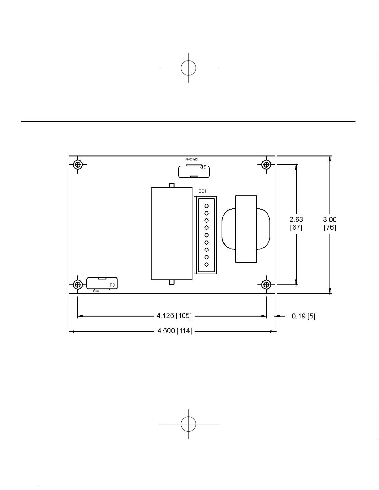
4
Dimensional Data
Figure 1. Dimensions
ALL DIMENSIONS IN INCHES [MILLIMETERS]
250-0021r5_readers.qxd 7/11/01 9:18 AM Page 4

5
Figure 2. SL10U Connections
PL1
CW
250-0021r5_readers.qxd 7/11/01 9:18 AM Page 5

6 Installation
The SL10U is an uncased chassis model and is designed to be
installed in original equipment. The speed adjust pot (P1) and its
mounting hardware is supplied with the control. Mount the speed
adjust pot through a 3/8" hole with the insulator disc between the pot
and the inside of the panel. The lock washer is placed between the
outside of the panel and the locknut. Mount the chassis to
appropriate subplates using the four threaded (6-32) mounting
stand-offs (refer to figure 1 on page 4 for mounting dimensions).
The chassis has adequate heat sinking to properly dissipate the
load-generated heat and can be either vertically or horizontally
mounted.
Installation
The SL10U is not isolated from earth ground. Unless
an isolation transformer is used, circuit components
are at a potential of 115 volts above ground. Please
refer to Safety Warnings on page i before installing.
Warning
250-0021r5_readers.qxd 7/11/01 9:18 AM Page 6

7
Leave enough room around the outer dimensions of the chassis to
allow access to the chassis after installation for removal, installing
wiring, calibration and other related reasons. Connect the SL10U
as shown in Figure 2 (page 5), and as described below.
1. Connect the speed adjust pot to its appropriate wires. These 3
wires should NOT be bundled with the motor and power line
leads because induced voltages could cause erratic operation.
If the speed adjust pot requires wiring longer than 18 inches
(0.5m), a shielded cable must be used. Do not ground both ends
of the shield.
2. Connect the motor to its appropriate wires. If the motor rotates
in the wrong direction, remove line voltage and reverse the
motor armature leads. Do NOT plug reverse the motor.
Installation
250-0021r5_readers.qxd 7/11/01 9:18 AM Page 7

8 Installation
3. Connect the power line to its appropriate wires. The hot leg of
the power line should be fused with a fast blow 0.5 amp fuse to
protect the control. The motor may be started and stopped with
the power line at any speed setting on the speed adjust pot. The
motor coasts to a stop when the power line is disconnected. If
dynamic braking is desired, see
Dynamic Braking
on page 29.
Minarik strongly recommends the installation of an emergency
stop switch as shown in Figure 2 (page 5). The switch must be
rated at a minimum of 250 VAC and 150% of the maximum
motor armature rating.
Alternative Wiring
By utilizing additional components the SL10U may be operated by
external signal control, have multiple preset speeds, dynamic
braking, limit switch operation, etc. Please refer to
Application
Notes
(page 14) for these and other modes of operation.
250-0021r5_readers.qxd 7/11/01 9:18 AM Page 8

9
IMPORTANT: A non-metallic screwdriver should be used when
adjusting the trim pots to avoid any possibility of the screwdriver’s
blad contacting live circuitry and shorting the circuitry or allowing
contact with any dangerous or fatal voltages.
Dangerous voltages exist on the printed circuit
board. Contact with components and/or printed
circuitry could cause serious injury or fatality. Please
refer to the Safety Warnings on page i.
Warning
Maximum Speed and Regulation (IR COMP) Adjustment
Two potentiometers, located on the control PC board, are provided
for adjustment of the maximum motor speed and regulation of the
motor’s speed.
Calibration
250-0021r5_readers.qxd 7/11/01 9:18 AM Page 9

10 Calibration
MAXIMUM SPEED ADJUSTMENT
This feature is provided to allow the motor speed to be adjusted
between 85 to 115% of motor name plate rated speed when the
speed adjust knob is set at maximum.
REGULATION (IR COMPENSATION)
Regulation is obtained by circuitry which raises the armature
voltage to maintain speed when increased loading tends to slow the
motor down.
250-0021r5_readers.qxd 7/11/01 9:18 AM Page 10

11Calibration
The control has been factory calibrated and no further adjustments
should be necessary. However, since the control was calibrated
using a speed adjust pot (P1) of 10K ohms and the pot shipped with
the control has a tolerance of ± 5%, the maximum speed could be
higher or lower than 1800 RPM. If the maximum speed is not
satisfactory, if the control has been repaired, or if you want to make
any changes, then follow the procedure listed below.
1. Disconnect the power line.
2. Set the speed adjust knob to “0” (full CCW).
3. Set the MAXIMUM SPEED trim pot to full CCW (refer to Figure
3 on page 13).
4. Set the REGULATION trim pot to full CCW (refer to Figure 3 on
page 13).
5. Read and follow the SAFETY WARNING on page i.
6. With no load on the motor, apply 115 VAC to the control and
advance the speed adjust knob to “100” (full CW).
Standard Calibration
250-0021r5_readers.qxd 7/11/01 9:18 AM Page 11

12 Calibration
7. Adjust the MAXIMUM SPEED trim pot for motor base speed at
no load.
8. Load the motor to full load and adjust the REGULATION trimpot
to obtain the same speed as at no load.
250-0021r5_readers.qxd 7/11/01 9:18 AM Page 12
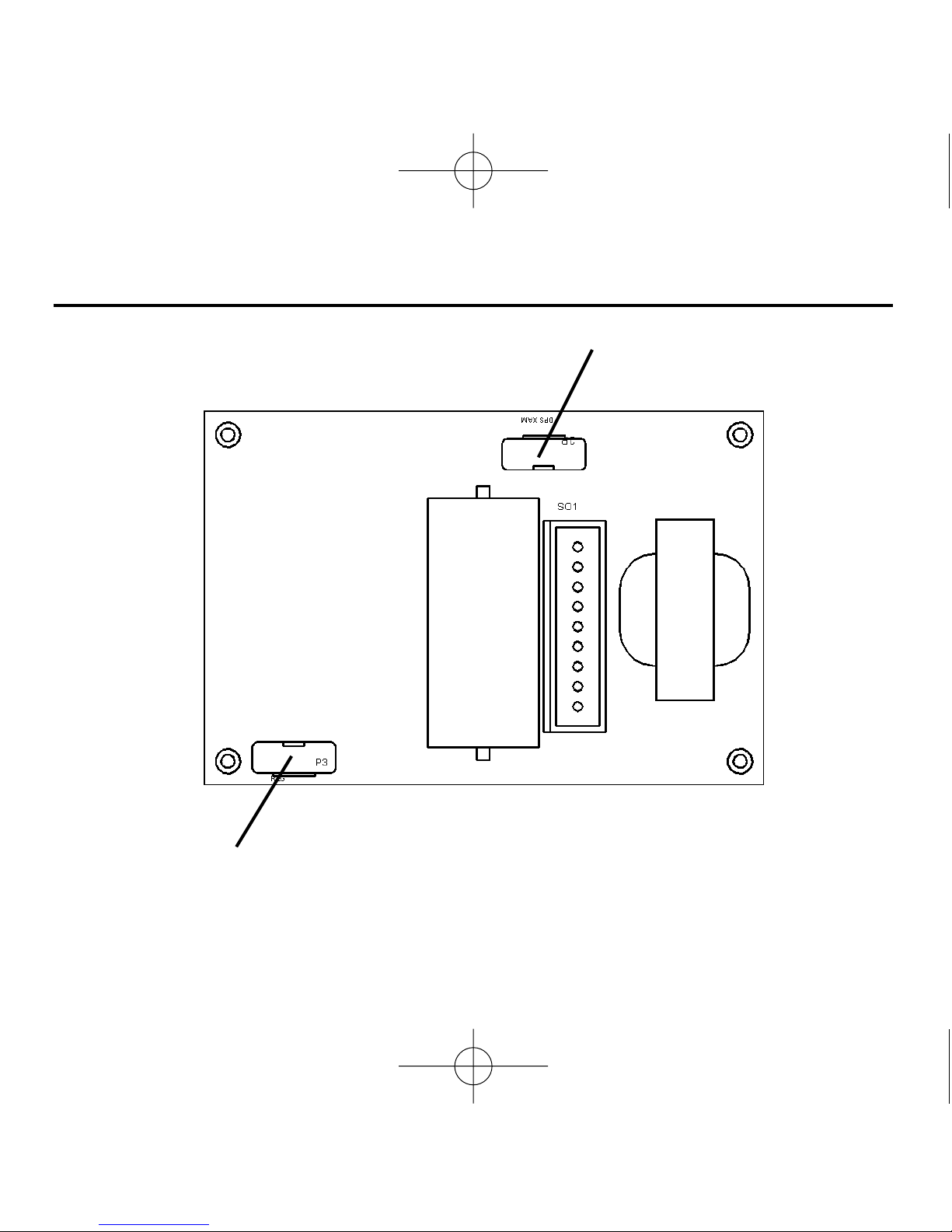
13Calibration
Figure 3. Maximum Speed and Regulation Trimpot Locations
MAXIMUM SPEED
REGULATION (IR COMP)
250-0021r5_readers.qxd 7/11/01 9:18 AM Page 13

14
DISCLAIMER - The following circuitry does not purport to cover all
possible details or variations, nor to provide for every possible
contingency to be met with connection, installation, operation, or
maintenance, and no warranty of fitness for purpose is expressed or
implied. Furthermore, Minarik Corporation assumes no
responsibility for the use of any circuitry described and makes no
representation that they are free from patent infringement.
Application Notes
The components shown in the following circuitry
should only be connected by qualified electrical
personnel familiar with the construction, operation,
and hazards of all the components used. Personal
injury and/or equipment damage may occur if
components are improperly connected, installed,
adjusted, or serviced. Also refer to the Safety
Warnings on page i.
Warning
250-0021r5_readers.qxd 7/11/01 9:18 AM Page 14
Table of contents
Other Minarik Control Unit manuals


Popular Control Unit manuals by other brands


Z-World
Z-World RabbitCore user manual

Homelife
Homelife CT2 24 UNI DL Instructions and warnings for installation, use and maintenance

Alfalaval
Alfalaval 660 instruction manual

SimCom
SimCom SIM300DZ Guidelines

Circa Enterprises Inc.
Circa Enterprises Inc. Guardian Telecom PTR Installation & operation

Redline
Redline RDL-3000 Series product manual

BOSSCO
BOSSCO Ecomaxx Supplemental manual

Texas
Texas TPS25940EVM-635 user guide

Panasonic
Panasonic PAN1326C2 quick start guide

3Com
3Com CoreBuilder 9000 ATM Interface Module quick start guide

Richter
Richter GU/F Series Installation and operating manual

AVR
AVR AVK Series Installation, operation and maintenance manual