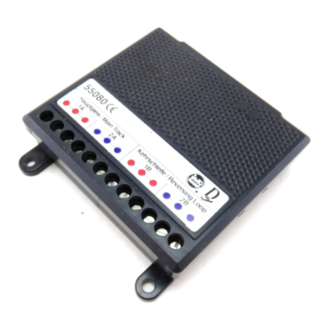
Minarik PCM4 User manual

USER’S MANUAL
PROCESS CONTROL
MODULE PCM4

Copyright 2001 by
Minarik Corporation
All rights reserved. No part of this manual may be reproduced or transmitted in any
form without written permission from Minarik Corporation. The information and
technical data in this manual are subject to change without notice. Minarik
Corporation and its Divisions make no warranty of any kind with respect to this
material, including, but not limited to, the implied warranties of its merchantability
and fitness for a given purpose. Minarik Corporation and its Divisions assume no
responsibility for any errors that may appear in this manual and make no
commitment to update or to keep current the information in this manual.
Printed in the United States of America.

Safety Warnings
•This symbol m denotes an important safety tip or warning.
Please read these instructions carefully before performing
any of the procedures contained in this manual.
•DO NOT INSTALL, REMOVE, OR REWIRE THIS
EQUIPMENT WITH POWER APPLIED. Have a qualified
electrical technician install, adjust and service this equipment.
Follow the National Electrical Code and all other applicable
electrical and safety codes, including the provisions of the
Occupational Safety and Health Act (OSHA), when installing
equipment.
•Reduce the chance of an electrical fire, shock, or explosion by
proper grounding, over-current protection, thermal protection,
and enclosure. Follow sound maintenance procedures.
Circuit potentials are at 120 VAC or 240 VAC above earth
ground. Avoid direct contact with the printed circuit board
or with circuit elements to prevent the risk of serious injury
or fatality. Use a non-metallic screwdriver for adjusting the
calibration trimpots. Use approved personal protective
equipment and insulated tools if working on this drive with
power applied.
m
i

Safety Warnings . . . . . . . . . . . . . . . . . . . . . . . . . . . . . . . . . .i
Specifications . . . . . . . . . . . . . . . . . . . . . . . . . . . . . . . . . . . .1
Dimensions . . . . . . . . . . . . . . . . . . . . . . . . . . . . . . . . . . . . . .2
Introduction . . . . . . . . . . . . . . . . . . . . . . . . . . . . . . . . . . . . . .3
Installation . . . . . . . . . . . . . . . . . . . . . . . . . . . . . . . . . . . . . . .4
Mounting . . . . . . . . . . . . . . . . . . . . . . . . . . . . . . . . . . . . . . .4
Wiring . . . . . . . . . . . . . . . . . . . . . . . . . . . . . . . . . . . . . . . . .5
Shielding guidelines . . . . . . . . . . . . . . . . . . . . . . . . . . . . .6
Screw terminal block . . . . . . . . . . . . . . . . . . . . . . . . . . . . . .7
Connections . . . . . . . . . . . . . . . . . . . . . . . . . . . . . . . . . . . . .8
AC line connections . . . . . . . . . . . . . . . . . . . . . . . . . . . . .8
Input signal connections . . . . . . . . . . . . . . . . . . . . . . . .10
Master signal generator . . . . . . . . . . . . . . . . . . . . . . . . . . .11
Output voltage connections . . . . . . . . . . . . . . . . . . . . . . . .14
Multiple follower requirements . . . . . . . . . . . . . . . . . . . . . .17
MM30000 series . . . . . . . . . . . . . . . . . . . . . . . . . . . . . .17
Multiple drives following a single signal input . . . . . . . . .19
Master PCM4 with multiple drives following . . . . . . . . . .20
ii
Contents

iii
Calibration . . . . . . . . . . . . . . . . . . . . . . . . . . . . . . . . . . . . . .21
Signal Input Adjust . . . . . . . . . . . . . . . . . . . . . . . . . . . . . .22
DIP switches . . . . . . . . . . . . . . . . . . . . . . . . . . . . . . . . . . .23
Input signal calibration . . . . . . . . . . . . . . . . . . . . . . . . . . . .24
Input voltage calibration . . . . . . . . . . . . . . . . . . . . . . . . . .24
Input current calibration . . . . . . . . . . . . . . . . . . . . . . . . . . .25
Troubleshooting . . . . . . . . . . . . . . . . . . . . . . . . . . . . . . . . .26
Before troubleshooting . . . . . . . . . . . . . . . . . . . . . . . . . . .26
Unconditional Warranty . . . . . . . . . . . . . . .inside back cover

iv
Figure 1. Process Control Module (PCM4) Dimensions . . . . . . . . . .2
Figure 2. Screw Terminal Block . . . . . . . . . . . . . . . . . . . . . . . . . . . .7
Figure 3. 115 VAC Power Connection . . . . . . . . . . . . . . . . . . . . . . .9
Figure 4. 230 VAC Power Connection . . . . . . . . . . . . . . . . . . . . . . .9
Figure 5. Connection – Following an External Signal . . . . . . . . . . .10
Figure 6. Unidirectional Manual Master Signal Source Connection .13
Figure 7. Bidirectional Manual Master Signal Source Connection . .13
Figure 8. Connection – Output Voltage . . . . . . . . . . . . . . . . . . . . . .16
Figure 9. Connection – Multiple Follower System . . . . . . . . . . . . . .18
Figure 10. Signal Input Adjust . . . . . . . . . . . . . . . . . . . . . . . . . . . .19
Figure 11. Connection – Ratio Potentiometers Multiple
Follower System . . . . . . . . . . . . . . . . . . . . . . . . . . . . . .20
Figure 12. SIGNAL INPUT ADJ - Calibration Positions . . . . . . . . . .22
Figure 13. DIP Switch Settings . . . . . . . . . . . . . . . . . . . . . . . . . . . .23
Illustrations

1
Specifications
Power Requirements
Line input 120/240 VAC, 50/60 Hz, single phase
Input Signal Ranges (input circuit is isolated)
Voltage signal
Narrow range –25 to +25 VDC
Wide range –250 to +250 VDC
Current signal 1–5 mADC, 4–20 mADC, 10–50 mADC
Input Impedance
Voltage signal >25K ohms
Current signal
1–5 mADC 1K ohm
4–20 mADC 235 ohms
10–50 mADC 100 ohms
Output
Impedance 800 ohms
Voltage range, max –10 to +10 VDC
Linearity 0.01%
Operating Temperature Range 0 – 50 °C

2
Dimensions
C507
P501
C504
IC504
IC503 TB502
MODEL PCM4
2.1 WATTS
120/240 VAC
TB501
1
T501
+15
INPUT ADJ
SIGNAL
65
C508
-15
C501
C502 C506
IC502
C503
C505
IC501
INPUT 1
7 8
COM
SW501
R501
910
INPUT 2 TP
IC505
10-50MA
4-20MA
1-5MA
P502P503
OUT
MAX OUT
MIN
21
0-±10VDC OUTPUT
R
R
12 3
WWW.MINARIKCORP.COM
1.93 [49]
2.70 [69]
4.83 [123]
0.35 [9]
1.30 [33]
4.22 [107]
4x 0.25 [6] STANDOFF
USE #8 PANHEAD SCREWS
Figure 1. Process Control Module (PCM4) Dimensions
ALL DIMENSIONS IN INCHES [MILLIMETERS]
4.83 [123]
1.93 [49]
2.70 [69]
1.30 [33]
0.35 [9] 4.22 [107]
4 x 0.25 [6] STANDOFF
USE #8 PANHEAD SCREWS

Model PCM4 accepts a grounded or floating, bipolar, DC signal
input and generates a proportional floating output voltage. The
output of the PCM4 follows the variations of its input: it increases
as the signal increases and decreases as the signal decreases.
This output can be supplied to the speed setting circuit of a motor
drive to rotate the motor at a speed proportional to the signal
input. Because the PCM4 can follow bipolar input voltage
signals, it can drive a regenerative variable speed drive through
the complete range of motor speeds in both forward and reverse
directions.
This manual contains specifications, installation procedures,
connections, and calibration procedures for the process control
module, model PCM4. Refer to your variable speed drive user’s
manual for additional installation, operation, and troubleshooting
procedures.
3
Introduction

4
Mounting
•PCM4 components are sensitive to electrostatic fields. Avoid
contact with the circuit board directly.
•Protect the PCM4 from dirt, moisture, and accidental
contact. Provide sufficient room for access to the terminal
block.
•Mount the PCM4 away from other heat sources. Operate
within the specified ambient operating temperature range.
The operating temperature range for the PCM4 is 0°C
through 50°C.
•Prevent loose connections by avoiding excessive vibration of
the process control module board.
•Mount the PCM4 in either a horizontal or vertical plane.
•The PCM4 is mounted using 4 – 0.25 inch [6mm] standoffs.
See Figure 1, page 2 for the physical locations of these
standoffs. Use #8 panhead screws to fasten the standoffs to
the mounting surface.
Warning
Do not install, rewire, or remove this control with input
power applied. Doing so may cause fire or serious injury.
Make sure you have read and understood the Safety
Warnings before attempting installation.
m
Installation

5
• Use 18-24 AWG wire for signal wiring. Use 16-18 AWG wire
for AC line (L1, L2) wiring.
Installation
Warning
Do not install, remove, or rewire this equipment with power
applied. Failure to heed this warning may result in fire,
explosion, or serious injury.
Circuit potentials are at 120 or 240 VAC above ground. To
prevent the risk of injury or fatality, avoid direct contact with
the printed circuit board or with circuit elements.
m
(
Wiring

6Installation
As a general rule, Minarik recommends shielding of all
conductors.
If it is not practical to shield power conductors, Minarik
recommends shielding all logic-level leads. If shielding of logic
level leads is not practical, the user should twist all logic leads
with themselves to minimize induced noise.
It may be necessary to earth ground the shielded cable. Do not
ground both ends of the shield.
If the drive continues to pick up noise after grounding the shield,
it may be necessary to add AC line filtering devices, or to mount
the drive in a less noisy environment.
Logic wires from other input devices, such as motion controllers
and PLL velocity controllers, must be separated from power lines
in the same manner as the logic I/O on the PCM4.
Shielding guidelines
Warning
Under no circumstances should power and logic leads be
bundled together. Induced voltage can cause unpredictable
behavior any electronic device.
m

7
Screw terminal block
Connections to Minarik’s PCM4 are made to a screw terminal
block. Using a screwdriver, turn the terminal block screw counter-
clockwise to open the wire clamp. Insert stripped wire into the
wire clamp. Turn the terminal block screw clockwise to clamp the
wire. See Figure 2.
Figure 2. Screw Terminal Block
Installation

8Installation
AC line connections
When operating on 120 VAC, leave the jumper bars installed
between terminals 1 and 2 and between 3 and 4 (see Figure 3).
This is how the unit is shipped from the factory. When operating
on 230VAC, remove both jumper bars and place one jumper bar
between terminals 2 and 3 (see Figure 4).
Connect the AC power leads to terminals 1 and 4.
Warning
Do not connect this equipment with power applied.
Failure to heed this directive may result in fire or
serious injury.
Minarik strongly recommends the installation of a
master power switch in the voltage input line. The
switch contacts should be rated at 2 amps AC and
250 volts.
m
Connections

9
Figure 4. 230 VAC Power Connection
P501
C504
IC504
TB501 +15
65
-15 INPUT 1
7 8
COM
SW501
R501
9
10
INPUT 2
TP
R
14
AC POWER
230 VAC
P501
C504
IC504
TB501 +15
65
C508
-15
C503
INPUT 1
7 8
COM
SW501
R501
9
10
INPUT 2
TP
R
14
AC POWER
115 VAC
Figure 3. 115 VAC Power Connection
Installation
1 4
AC POWER
115 VAC
1 4
AC POWER
230 VAC

10 Installation
Input signal connections
Connect the incoming voltage or current signal leads to
INPUT 1 (terminal 8) and to COM (terminal 7). If the maximum
input voltage will exceed 25V, connect the signal leads to INPUT
2 (terminal 9) and to COM (terminal 7). See Figure 5 below.
Use insulated shielded wire or twisted pair for PCM4 input and
output signal leads longer than 18 inches. Connect the shielding
to earth ground at the end away from the PCM4 and trim the
exposed shielding at the PCM4 to preclude accidental grounding
of the PCM4.
Bundle the signal-carrying leads separately from the motor leads
or AC power leads.
P501
C504
+15
65
-15 INPUT 1
7 8
COM
910
INPUT 2 TP
1
R
VOLTAGE SIGNAL RANGE
0 - ±25VDC
CURRENT SIGNAL RANGES
1 - 5mA
4 - 20mA
10 - 50mA
SIG (+)COM (-)
P501
+15
65
-15 INPUT 1
7 8
COM
910
INPUT 2 TP
1
R
VOLTAGE SIGNAL RANGE
0 - ±250VDC
SIG (+)COM (-)
Figure 5. Connection – Following an External Signal
COM (-)
VOLTAGE SIGNAL RANGE
0 - ±25 VDC
CURRENT SIGNAL RANGES
1 - 5 mA
4 - 20 mA
10 - 50 mA
SIG (+) COM (-)
VOLTAGE SIGNAL RANGE
0 - ±250 VDC
SIG (+)

11
Master signal generator
The PCM4 can be used as a master controller to:
(1) provide a floating DC master voltage input to other PCM4
modules interfacing with standard variable speed drives or
(2) to drive several variable speed drives directly, provided that
their circuit design permits wiring of their speed circuits in
common.
Unidirectional applications require a positive PCM4 output.
Connect a 10K ohm potentiometer (not provided with the PCM4)
as the master control pot using the +15 VDC supply on the
PCM4.
The normal wiring of an external master control potentiometer is
the CW side of the potentiometer to +15 V supply (terminal 6),
and the CCW side to COM (terminal 7). The potentiometer wiper
is connected to INPUT 1 (terminal 8). See Figure 6 (page13) .
The potentiometer is rotated clockwise to increase the voltage at
INPUT 1 and, therefore, increasing the PCM4 output voltage.
Warning
Bidirectional output mode should never be used with
standard SCR (single quadrant) variable speed drives.
These drives only respond to one polarity in their speed
setting circuits.
m
Installation

12 Installation
Bipolar input is necessary to control motor reversals when the
motor is being driven by a four quadrant, regenerative variable
speed drive.
To wire the external master control potentiometer to provide a
bipolar, adjustable voltage input signal, wire the potentiometer
across the –15 and +15V supply terminals, with the CW end at
+15V. Connect the pot wiper to the INPUT 1 (terminal 8). See
Figure 7 (page 13).
The center position of the wiper produces zero input voltage.
Potentiometer rotation CW from center produces increasing
positive voltage; CCW rotation from center produces increasing
negative voltage.

13
Figure 7. Bidirectional Manual Master Signal Source Connection
C504
TB501
+15
65
-15 INPUT 1
7 8
COM
9
INPUT 2
-
10K OHM
SPEED ADJUST
POTENTIOMETER
(NOT PROVIDED)
+
Figure 6. Unidirectional Manual Master Signal Source Connection
C504 +15
65
-15 INPUT 1
7 8
COM
910
INPUT 2 TP
CW
10K OHM
SPEED ADJUST
POTENTIOMETER
(NOT PROVIDED)
Installation
10K OHM
SPEED ADJUST
POTENTIOMETER
(NOT PROVIDED)
10K OHM
SPEED ADJUST
POTENTIOMETER
(NOT PROVIDED)
-
+
CW

14 Installation
Output connections are made to the small terminal block on the
board (TB502). Connect the output leads to terminal 1 and 2
(Figure 8, page 16). When the input signal at INPUT1 is positive
with respect to COM terminal 2 will be positive.
The exception to this polarity rule occurs when the PCM4 has
been calibrated to bias its output as a voltage follower. An input
of zero volts can be calibrated to produce a finite positive or
negative output voltage.
The PCM4 output is a floating DC voltage. It is brought into the
speed setting circuit of a variable speed drive to replace the main
speed adjust potentiometer.
Output voltage connections
Warning
Always check the instruction manual supplied with the
variable speed drive that will be interfaced with the PCM4
module. The scheme shown for wiring to an external voltage
source, as well as the specifications on that input, must be
well understood before proceeding.
m
Table of contents
Other Minarik Control Unit manuals
