Minarik VT7 Series User manual

USER’S MANUAL
Model VT7
VISI-TACH® Multi-Functional
Digital Indicator
250-0257 rev 1.qxd 4/9/01 10:42 AM Page I

Copyright © 1998 by
Minarik Corporation
All rights reserved. No part of this manual may be reproduced or transmitted in any
form without written permission from Minarik Corporation. The information and tech-
nical data in this manual are subject to change without notice. Minarik Corporation
and its Divisions make no warranty of any kind with respect to this material, includ-
ing, but not limited to, the implied warranties of its merchantability and fitness for a
given purpose. Minarik Corporation and its Divisions assume no responsibility for
any errors that may appear in this manual and make no commitment to update or
keep current the information in this manual.
Printed in the United States of America.
250-0257 rev 1.qxd 4/9/01 10:42 AM Page II

Safety Warnings
•This symbol denotes an important safety tip or warning.
Please read these sections carefully prior to performing any of
the instructions contained in that section.
•Have a qualified electrical maintenance technician install,
adjust, and service this equipment. Follow the National
Electrical Code and all other applicable electrical and safety
codes, including the provisions of the Occupational Safety
and Health Act (OSHA) when installing equipment.
•Reduce the chance of an electrical fire, shock, or explosion
by proper grounding, over current protection, thermal pro-
tection, and enclosure. Follow sound maintenance proce-
dures.
•The VISI-TACH®is isolated from earth ground. Circuit
potentials are at 115 VAC or 230 VAC above earth ground.
Avoid direct contact with the printed circuit board or with
circuit elements to prevent the risk of serious injury or
fatality. Use a non-metallic screwdriver for any necessary
adjustments.
250-0257 rev 1.qxd 4/9/01 10:42 AM Page i

ii
250-0257 rev 1.qxd 4/9/01 10:42 AM Page ii

Contents
Specifications 1
Dimensions 2
General Information 3
Installation 4
General installation information ..................................4
Screwterminalblock..........................................5
Mounting...................................................6
Shielded cable ..............................................7
Connections ................................................8
Programming 9
Slideswitch................................................10
DIP switches ...............................................10
Rotary DIP switches - time base calculations .......................12
Application Examples 15
Mode1tachometermode-example1 ...........................15
Mode1tachometermode-example2 ...........................17
Mode2totalizermode........................................22
Mode3ratemonitormode ....................................24
Mode4ratemonitormode(min-secformat) .......................26
iii
250-0257 rev 1.qxd 4/9/01 10:42 AM Page iii

250-0257 rev 1.qxd 4/9/01 10:42 AM Page iv

Specifications
AC Line Voltage
VT7-115 115 VAC +/- 10%, 50/60 Hertz, 5.5 Watts
VT7-230 230 VAC +/- 10%, 50/60 Hertz, 5.5 Watts
Programmable Power Supply Output
5VDC@50mA 50 mA, Regulated Source, +/- 4%
12VDC@25mA 25 mA, Unregulated Source, +/- 20%
Operating Temperature Range 10°C–40°C
Maximum Input Rate 20000 Pulses per Second
Feedback Frequency Range 10 – 20000 Hz
LED Readout Size 0.7 inches
250-0257 rev 1.qxd 4/9/01 10:42 AM Page 1
2
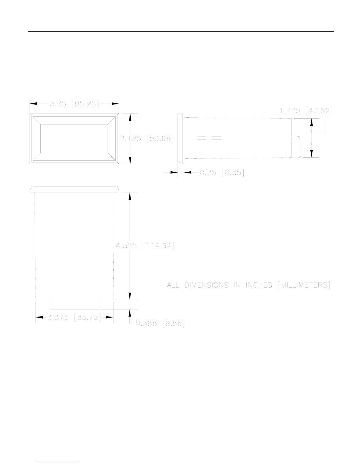
Figure 1. Model VT7-115 and Model VT7-230
Multi-Functional Digital Indicator Dimensions
Dimensions
250-0257 rev 1.qxd 4/9/01 10:42 AM Page 2

3
General Information
Minarik Corporation’s VISI-TACH®models VT7-115 and
VT7-230 provide a means for monitoring the speed of rotat-
ing shafts using a digital velocity transducer. Speed transduc-
ers such as magnetic pickup, optical encoders or hall effect
sensors convert motor speed into a small signal frequency
which is supplied to the VT7.
The VT7 is a multi-functional device and can be programmed
for use as a tachometer for display of revolutions per minute,
feet per minute, etc. It can also be used as a totalizer, a rate
monitor with a display of an inverse frequency, or a rate mon-
itor with a time format in hours and minutes, or minutes and
seconds.
The unit is programmable using a series of switches, located
under the rear panel access cover. The variables programmed
using these switches are the power supply (5 or 12 VDC), the
type of feedback (magnetic pickup or optical encoder), deci-
mal point location, and the mode the unit will operate in. The
rotary switches program the time base in seconds. Detailed
explanations of each one of these items follow in the pro-
gramming section of this manual (page 9).
250-0257 rev 1.qxd 4/9/01 10:42 AM Page 3

4
Installation
General installation information
The VT7 components are sensitive to electrostatic fields.
Avoid contact with the circuit board directly.
Protect the VT7 from dirt and moisture. Provide adequate
clearance for wiring and programming. This takes place at the
back of the unit.
Mount the VT7 away from other heat sources. Operate
within the specified ambient operating temperature range.
The operating temperature range for the VT7 is 10ºC
through 40ºC.
Prevent loose connections by avoiding excessive vibration of
the VT7.
250-0257 rev 1.qxd 4/9/01 10:42 AM Page 4
5
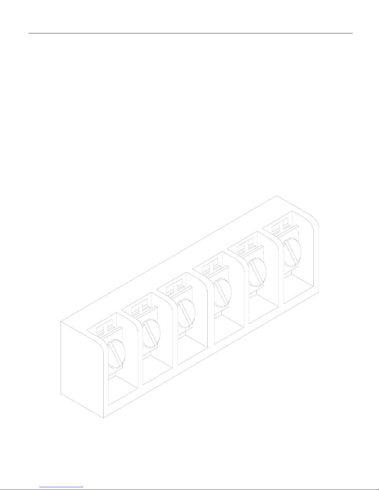
Installation
Screw terminal block
Connections to Minarik’s VT7 digital indicator are made to a
screw terminal block. The screw terminal block has a similar
connection style to the one shown below.
Using a screwdriver, turn the terminal block screw counter-
clockwise to open the wire clamp. Insert stripped wire into the
wire clamp. Turn the terminal block screw clockwise to clamp
the wire.
Fig. 2. Screw Terminal Block
250-0257 rev 1.qxd 4/9/01 10:42 AM Page 5

6Installation
Mounting
1. Cut a rectangular opening 1-25/32 inches [45mm] high by
3-3/8 inches [86mm] wide in your panel.
2. Unscrew the two mounting bracket screws until the thread-
ed end is almost flush with the threaded bushing.
3. Place the VISI-TACH®through the panel opening and
install the mounting bracket by engaging the two hooks on
each bracket into the two slots on each side of the unit, with
the threaded end of the screws towards the back of the
panel.
4. Screw the two mounting bracket screws in until they “bite”
into the rear of the panel. The screws should be tight
enough to prevent the VISI-TACH®from moving, but do
NOT over tighten the screws or you may damage your
panel.
250-0257 rev 1.qxd 4/9/01 10:42 AM Page 6

7
Installation
Shielded cable
Use shielded cable when logic lines are longer than 18 inches
(475 mm). Logic lines of this length act as an antenna and can
pick up noise from other devices or other ground wires, or
voltage from power lines that can cause erratic operation.
Attach the shield to the COM terminal on the back of the VT7
or the pickup source only.
It may be necessary to earth ground one end of the shielded
cable. Do not earth ground both ends of the shield.
250-0257 rev 1.qxd 4/9/01 10:42 AM Page 7

Connections
1. Connect the AC power line input on terminals L1 and L2.
This voltage is 115 VAC for the VT7-115 and 230 VAC for
the VT7-230.
2. Connect the pickup, encoder or transducer on the terminals
as indicated in the drawing below.
IMPORTANT! To prevent possible interference do NOT
run pickup, encoder, or transducer cable in same conduit
as the AC line.
Installation
8
Fig. 3. Connection Diagram
250-0257 rev 1.qxd 4/9/01 10:42 AM Page 8

9
Programming
The VT7 may be programmed before installing it into the
panel, and before connecting to the AC line and the pickup,
encoder or transducer, or after the entire system is set up. For
easier handling, it is usually more convenient to program the
VT7 before it is set in the panel.
For access to the programming switches, remove the two
screws holding the rear cover to the case and remove the
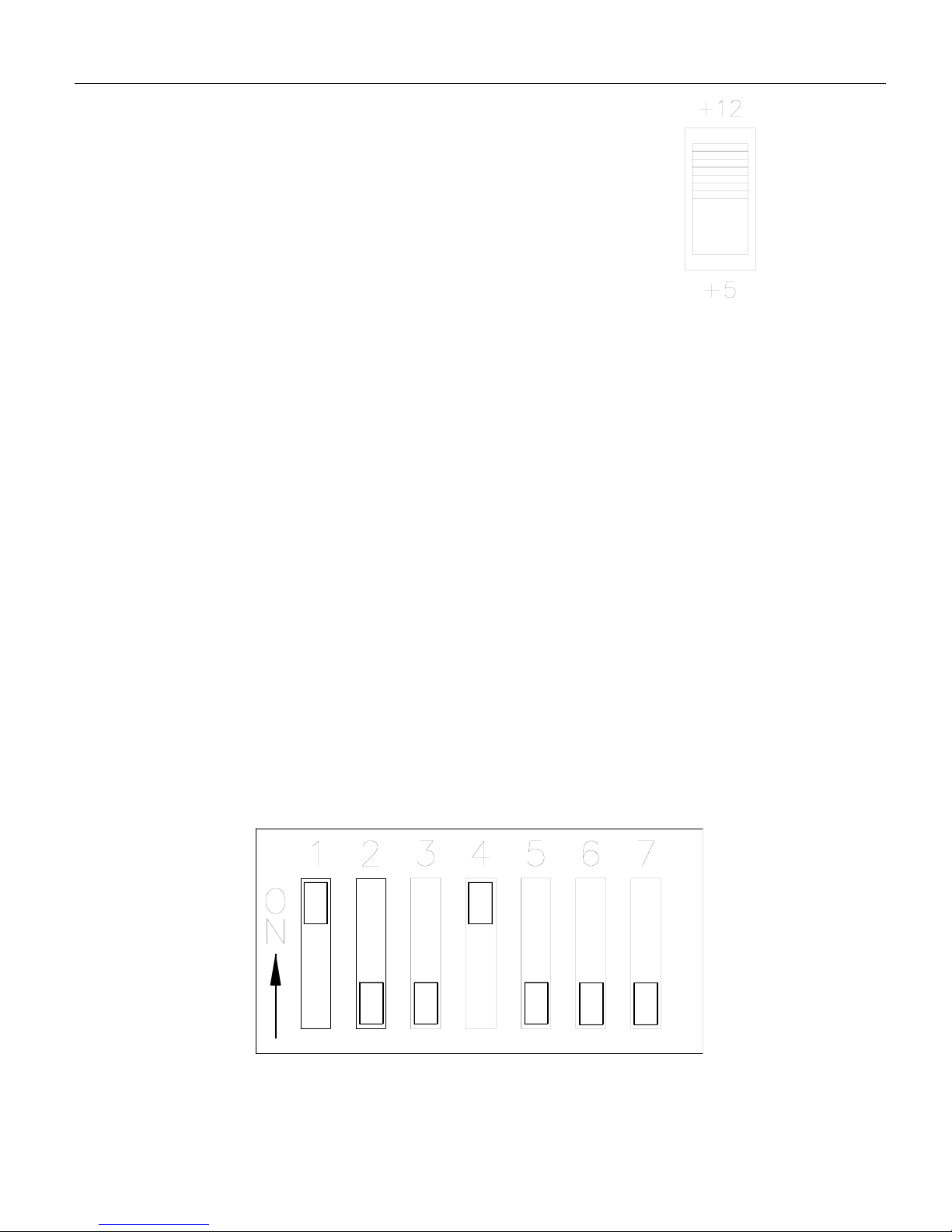
cover. The switches are illustrated in Figure 4.
Fig. 4. VT7 Programming Switches
250-0257 rev 1.qxd 4/9/01 10:42 AM Page 9
Programming
10
DIP switches
To change the position of the DIP switches use a small screw-
driver to push the DIP to the desired position. The DIP switch
block has a similar construction style to one shown below
(Figure 6). In the figure, the DIP switches are set for:
optical encoder (1 on and 2 off),
decimal point 00.00 (3 off, 4 on,and 5 off) ,
and tachometer mode (6 and 7 off).
Slide switch
The position of the slide switch deter-
mines the power supply output. Set
the slide switch to +5 or +12VDC to
power an optical encoder. For accura-
cy and current output of this
power supply see the specifica-
tions on page 1.
Fig. 6. VT7 DIP Switches
Fig. 5. VT7 Power
Supply Slide Switch
250-0257 rev 1.qxd 4/9/01 10:42 AM Page 10

11
Programming
Feedback type. DIP switches 1 and 2 are dependent upon
which type of feedback has been selected. See the table
below for the settings.
Decimal point selection. DIP switches 3, 4 and 5 determine
where the decimal point will light in the display. See the
table below for the settings. Only one switch may be on at
any time.
Mode selection. To select the mode in which VT7 will oper-
ate, use DIP switches 6 and 7.
Mode1isthetachometer mode (set 6 OFF and 7 OFF).
The tachometer mode displays the monitored shaft speed or
a multiple of it. The display can be frozen to the last reading
by shorting terminal COM to terminal H.
Feedback Type Switch #1 Switch #2
Magnetic pickup OFF ON
Optical encoder ON OFF
Decimal Location SW#3 SW#4 SW# 5
000.0 ON OFF OFF
00.00 OFF ON OFF
0.000 OFF OFF ON
0000 OFF OFF OFF
Mode of Operation SW#6 SW#7
Tachometer (1) OFF OFF
Totalizer (2) OFF ON
Rate Monitor Mode (3) ON OFF
Rate Monitor Mode (4) ON ON
250-0257 rev 1.qxd 4/9/01 10:42 AM Page 11

Programming
12
Mode2isthetotalizer mode (set 6 OFF and 7 ON). In this
mode the unit displays continuous count of pulses received
from the speed transducer. The display will turn over to 0000
after either 10,000 pulses have been received from the speed
transducer or the unit has been reset. The display can be reset
to zero by shorting terminal COM to terminal H.
Mode3istherate monitor mode (set 6 ON and 7 OFF). This
mode displays the time in process (or a linear multiple of it) in
seconds. The display in the rate monitor mode is inversely
proportional to the monitored shaft speed.
Mode 4 is the rate monitor mode (min:sec or hour:min for-
mat) (set 6 ON and 7 ON). In this mode the unit displays the
number in time format. This display can be used to read min-
utes and seconds, or hours and minutes. The display can be
frozen to the last reading by shorting terminal COM to termi-
nal H.
Rotary DIP switches - time base calculations
The programming variable which determines the display read-
ing is called the time base. The time base is the time interval
the VT7 uses to count the pulses from the speed transducer
and issue the result to the display.
The rotary DIP switches program the time base, in seconds,
from 0.01 seconds to 10.00 seconds. Settings of all zeros is
equal to a time base of 10.00 seconds. An explanation of the
time base calculation begins on page 14. The time base is pro-
grammed for modes 1, 3, and 4 only.
250-0257 rev 1.qxd 4/9/01 10:42 AM Page 12

Ideally, the time base should be set between .67 seconds and 2
seconds. If the time base is set below .67 seconds, the display
will update too often and tend to flicker. If the time base is set
greater than two seconds, the display reading will not update
often enough and may lag the actual speed of the application.
To program the rotary switches, use a small screwdriver and
set the pointer mark to the desired number.
The following application variables must be known before cal-
culating the time base (t):
DDN = The desired display number. DDN is the known dis-
play value at a certain shaft speed (RPM). It should be 4 digits
and ignore any decimal point present.
RPM = Revolutions per minute of the monitored shaft at the
time when the DDN is known.
PPR = Pulses per revolution of the pickup, encoder or trans-
ducer. This is the number of teeth on the pickup wheel or lines
on the optical encoder.
13
Programming
Fig. 7. VT7 Rotary DIP Switches
250-0257 rev 1.qxd 4/9/01 10:42 AM Page 13

Programming
14
Mode 1 (tachometer mode). The time base (t) is a variable
which scales the RPM of the monitored shaft at the location
of the speed transducer.
The RPM and DDN in the above equation are arbitrary val-
ues. Any RPM value may be chosen. The desired display
number for the RPM selected is then determined by the user’s
application.
Mode 2 (totalizer mode). Mode 2 has no time base.
Mode 3 (rate monitor mode). To calculate the time base in
mode 3 use the equation below:
Mode 4 (rate monitor mode (min:sec/hour:min format)).
In this mode we must convert the DDN to an hours and min-
utes (or minutes and seconds) format. This is done with the
following equation:
DDN = 60X + Y
where X = hours and Y = minutes when operating in the
hours and minutes mode, and X = minutes and Y = seconds
when operating in the minutes and seconds mode.
Calculate the time base with the following equation using the
DDN calculated with the equation above:
250,000 60
(DDN)(RPM) X
t= PPR
250,000 60
(DDN)(RPM) X
t= PPR
(DDN)(60)
(RPM)(PPR)
t=
250-0257 rev 1.qxd 4/9/01 10:42 AM Page 14
This manual suits for next models
5
Table of contents
Other Minarik Music Equipment manuals


