Minarik VT8 User manual

USER’S MANUAL
Model VT8
VISI-TACH® Multi-Functional
Digital Indicator
250-0293.qxd 4/13/00 9:40 AM Page a

Copyright © 2000 by
Minarik Corporation
All rights reserved. No part of this manual may be reproduced or transmitted in any
form without written permission from Minarik Corporation. The information and
technical data in this manual are subject to change without notice. Minarik
Corporation and its Divisions make no warranty of any kind with respect to this
material, including, but not limited to, the implied warranties of its merchantability
and fitness for a given purpose. Minarik Corporation and its Divisions assume no
responsibility for any errors that may appear in this manual and make no
commitment to update or keep current the information in this manual.
Printed in the United States of America.
250-0293.qxd 4/13/00 9:40 AM Page b

i
Safety Warnings
•This symbol denotes an important safety tip or warning.
Please read these instructions carefully before performing
any of the procedures contained in this manual.
•DO NOT INSTALL, REMOVE, OR REWIRE THIS
EQUIPMENT WITH POWER APPLIED. Have a qualified
electrical technician install, adjust and service this equipment.
Follow the National Electrical Code and all other applicable
electrical and safety codes, including the provisions of the
Occupational Safety and Health Act (OSHA), when installing
equipment.
•Reduce the chance of an electrical fire, shock, or explosion by
proper grounding, over-current protection, thermal protection,
and enclosure. Follow sound maintenance procedures.
Warning
Circuit potentials are at 115 VAC or 230 VAC above earth
ground. Avoid direct contact with the printed circuit board or
with circuit elements to prevent the risk of serious injury or
fatality.
250-0293.qxd 4/13/00 9:40 AM Page i

ii
250-0293.qxd 4/13/00 9:40 AM Page ii

Contents
iii
Specifications 1
Dimensions 2
General Information 3
Installation 5
General installation information . . ..................................5
Screw terminal block . . .........................................6
Mounting ....................................................7
Shielding guidelines ............................................8
Connections ..................................................9
AC Line voltage select switch ....................................10
Programming 11
DIP switches ................................................12
Encoder power supply (DIP switch #1) ...........................13
Feedback select (DIP switches 2 and 3) ..........................14
Decimal point selection (DIP switches 4, 5 and 6) ..................15
Mode selection (DIP switches 7 and 8) ...........................16
Rotary DIP switches . . . . . . . . . . . . . . . . . . . ......................17
Time base calculations .......................................18
Application Examples 23
Mode 1 (tachometer mode) - example 1 ..........................23
Mode 2 (totalizer mode) .....................................30
Mode 3 (time in process mode) ................................32
Mode 4 time in process mode (min:sec or hour:min format) ...........34
Unconditional Warranty 37
250-0293.qxd 4/13/00 9:40 AM Page iii

Illustrations
Figure 1. Dimensions ............................................2
Figure 2. Screw Terminal Block .....................................6
Figure 3. Connection Diagram .....................................9
Figure 4. Line Voltage Select Switch SW501 ..........................10
Figure 5. VT8 Programming Switches ...............................11
Figure 6. VT8 DIP Switches ......................................12
Figure 7. Encoder Power Supply DIP Switch ..........................13
Figure 8. Feedback Select DIP Switches .............................14
Figure 9. Decimal Point Location Select DIP Switches ...................15
Figure 10. Operating Mode Select DIP Switches ........................17
Figure 11. VT8 Rotary DIP Switches .................................18
Figure 12. Mode 1 Example One Switch Settings .......................24
Figure 13. Mode 1 Example Two Switch Settings .......................29
Figure 14. Mode 2 Totalizer Mode Example DIP Switch Settings ............31
Figure 15. Mode 3 Example DIP Switch Settings ........................33
Figure 16. Mode 4 Example DIP Switch Settings ........................35
iv
250-0293.qxd 4/13/00 9:40 AM Page iv

Specifications
Selectable AC Line Voltage (via switch SW501) 115 VAC +/- 10%, 50/60 Hz, 5.5 Watts
230 VAC +/- 10%, 50/60 Hz, 5.5 Watts
Selectable Power Supply Output (selected via switch SW502)
5VDC@50mA 50 mA, Regulated Source, +/- 4%
12VDC@25mA 25 mA, Unregulated Source, +/- 20%
Operating Temperature Range 10°C–40°C
Maximum Input Rate 20 kHz
Feedback Frequency Range 10 – 20000 Hz
LED Readout Size 0.7 inches
1
250-0293.qxd 4/13/00 9:40 AM Page 1
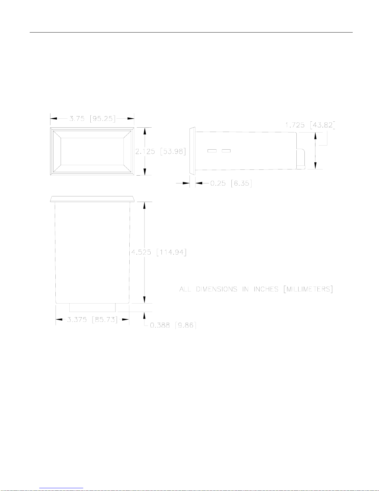
2
Figure 1. Model VT8
Multi-Functional Digital Indicator Dimensions
Dimensions
250-0293.qxd 4/13/00 9:40 AM Page 2

General Information
Minarik Corporation’s VISI-TACH®model VT8 provides a
means for monitoring the speed of rotating shafts using a
digital velocity transducer. Speed transducers such as
magnetic pickup, optical encoders or hall effect sensors
convert motor speed into a small signal frequency which is
supplied to the VT8.
The VT8 is a multi-functional device and can be programmed
for use as a tachometer for display of revolutions per minute,
feet per minute, etc. It can also be used as a totalizer, a time-
in-process monitor with a display of an inverse frequency, or a
time-in-process monitor with a time format in hours and
minutes, or minutes and seconds.
The unit is programmable using a series of switches, located
under the rear panel access cover. The variables programmed
using these switches are the power supply (5 or 12 VDC), the
type of feedback (magnetic pickup or optical encoder),
decimal point location, and the mode the unit will operate in.
The rotary switches program the time base in seconds.
Detailed explanations of each one of these items follow in the
programming section of this manual (page 11).
3
250-0293.qxd 4/13/00 9:40 AM Page 3

4
250-0293.qxd 4/13/00 9:40 AM Page 4

Installation
5
General installation information
The VT8 components are sensitive to electrostatic fields.
Avoid contact with the circuit board directly.
Protect the VT8 from dirt and moisture. Provide adequate
clearance for wiring and programming. This takes place at the
back of the unit.
Mount the VT8 away from other heat sources. Operate
within the specified ambient operating temperature range.
The operating temperature range for the VT8 is 10ºC
through 40ºC.
Prevent loose connections by avoiding excessive vibration of
the VT8.
Warning
Do not install, rewire, or remove this control with input
power applied. Doing so may cause fire or serious injury.
Make sure you have read and understood the Safety
Warnings on pg i before attempting installation.
250-0293.qxd 4/13/00 9:40 AM Page 5

Installation6
Screw terminal block
Connections to Minarik’s VT8 digital indicator are made to a
screw terminal block. The screw terminal block has a similar
connection style to the one shown below.
Using a screwdriver, turn the terminal block screw counter-
clockwise to open the wire clamp. Insert stripped wire into the
wire clamp. Turn the terminal block screw clockwise to clamp
the wire.
Figure 2. Screw Terminal Block
250-0293.qxd 4/13/00 9:40 AM Page 6

7
Installation
Mounting
1. Cut a rectangular opening 1-25/32 inches [45mm] high by
3-3/8 inches [86mm] wide in your panel.
2. Unscrew the two mounting bracket screws until the
threaded end is almost flush with the threaded bushing.
3. Place the VISI-TACH®through the panel opening and
install the mounting bracket by engaging the two hooks on
each bracket into the two slots on each side of the unit, with
the threaded end of the screws towards the back of the
panel.
4. Screw the two mounting bracket screws in until they “bite”
into the rear of the panel. The screws should be tight
enough to prevent the VISI-TACH®from moving, but do
NOT over tighten the screws or you may damage your
panel.
250-0293.qxd 4/13/00 9:40 AM Page 7

Installation8
Shielding guidelines
Under no circumstances should power and logic leads be
bundled together. Induced voltage can cause unpredictable
behavior any electronic device, including motor controls.
As a general rule, Minarik recommends shielding of all
conductors.
If it is not practical to shield power conductors, Minarik
recommends shielding all logic-level leads. If shielding is not
practical, the user should twist all logic leads with themselves
to minimize induced noise.
It may be necessary to earth ground the shielded cable. If
noise is produced by devices other than the VT8, ground the
shield at the VT8 end. If noise is generated by a device on the
VT8, ground the shield at the end away from the VT8. Do not
ground both ends of the shield.
If the VT8 continues to pick up noise after grounding the
shield, it may be necessary to add AC line filtering devices, or
to mount the VT8 in a less noisy environment.
250-0293.qxd 4/13/00 9:40 AM Page 8
9
Installation
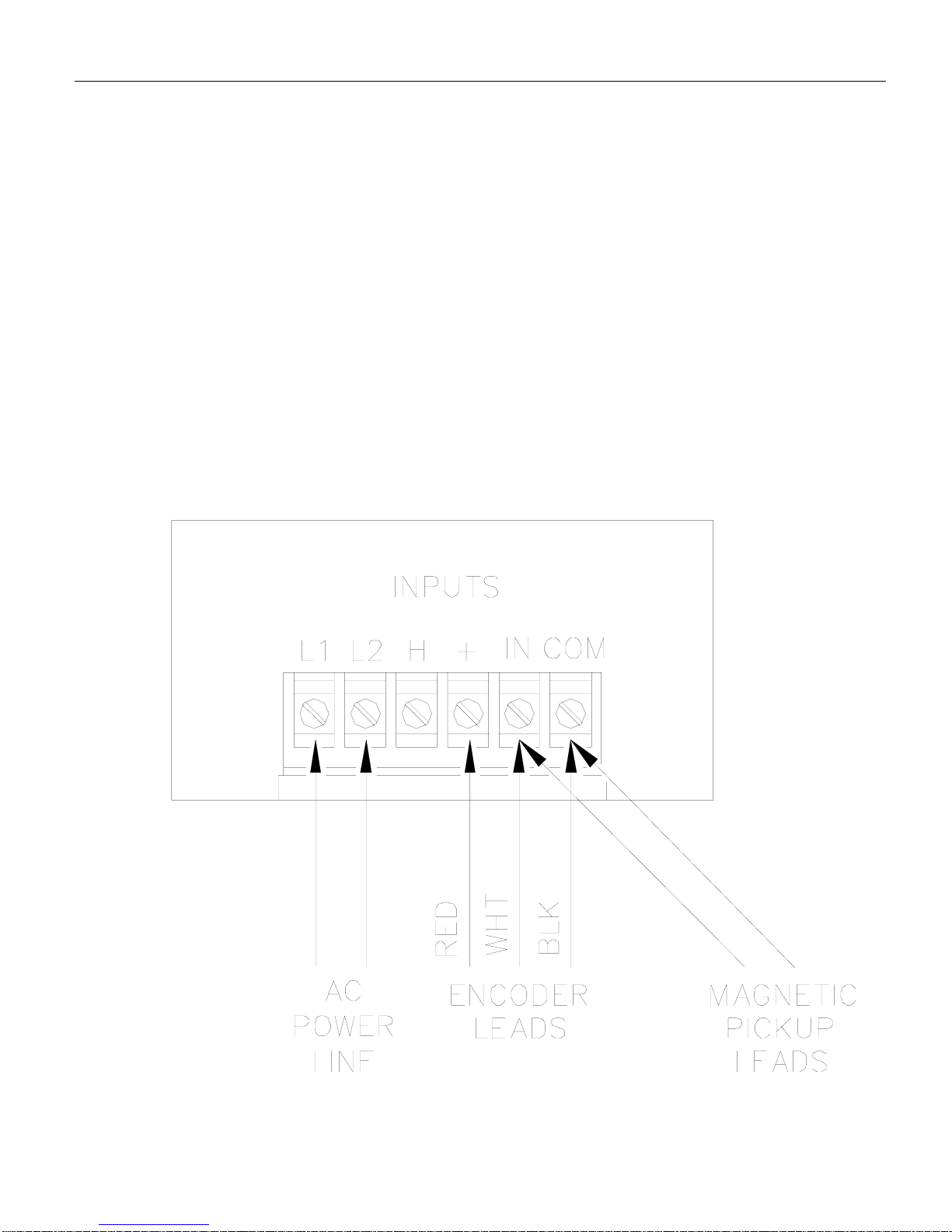
Connections
1. Connect the AC power line input on terminals L1 and L2.
This voltage may be either 115 or 230 VAC.
2. Connect the pickup, encoder or transducer on the terminals
as indicated in the drawing below.
IMPORTANT: To prevent possible interference do NOT
run pickup, encoder, or transducer cable in same conduit
as the AC line.
Figure 3. Connection Diagram
250-0293.qxd 4/13/00 9:40 AM Page 9
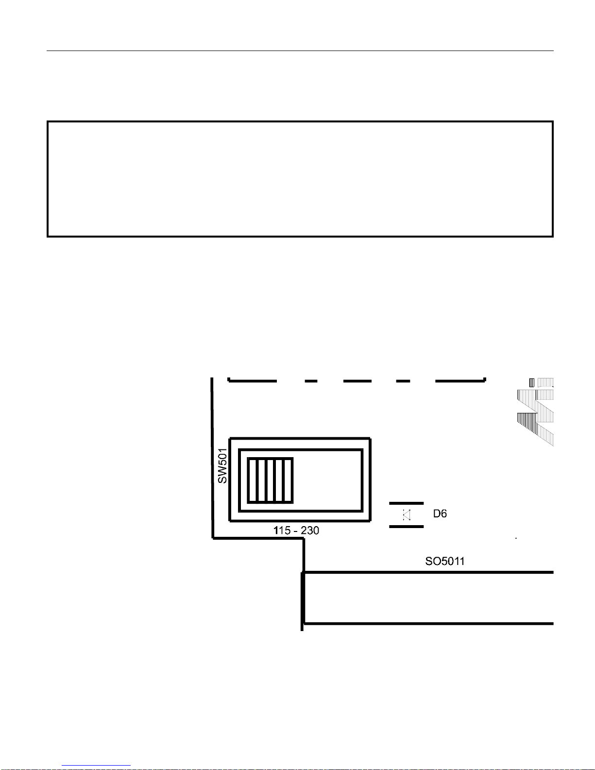
Line voltage select switch (SW501)
The VT8 is equipped with line-voltage select switch SW501
(Figure 4). Set this switch to 115 if using a 115 VAC line
voltage input. Set the switch to 230 if using a 230 VAC line
voltage input.
Installation10
Figure 4. Line Voltage Select Switch SW501
ATTENTION: Change voltage switch settings only when the
VT8 is disconnected from AC line voltage. Make sure the
switch is set to its correct position before applying power. If
the switch is improperly set to a lower voltage position, the
transformer may be damaged.
250-0293.qxd 4/13/00 9:40 AM Page 10
Programming
The VT8 may be programmed before installing it into the
panel, and before connecting to the AC line and the pickup,
encoder or transducer, or after the entire system is set up. For
easier handling, it is usually more convenient to program the
VT8 before it is set in the panel.
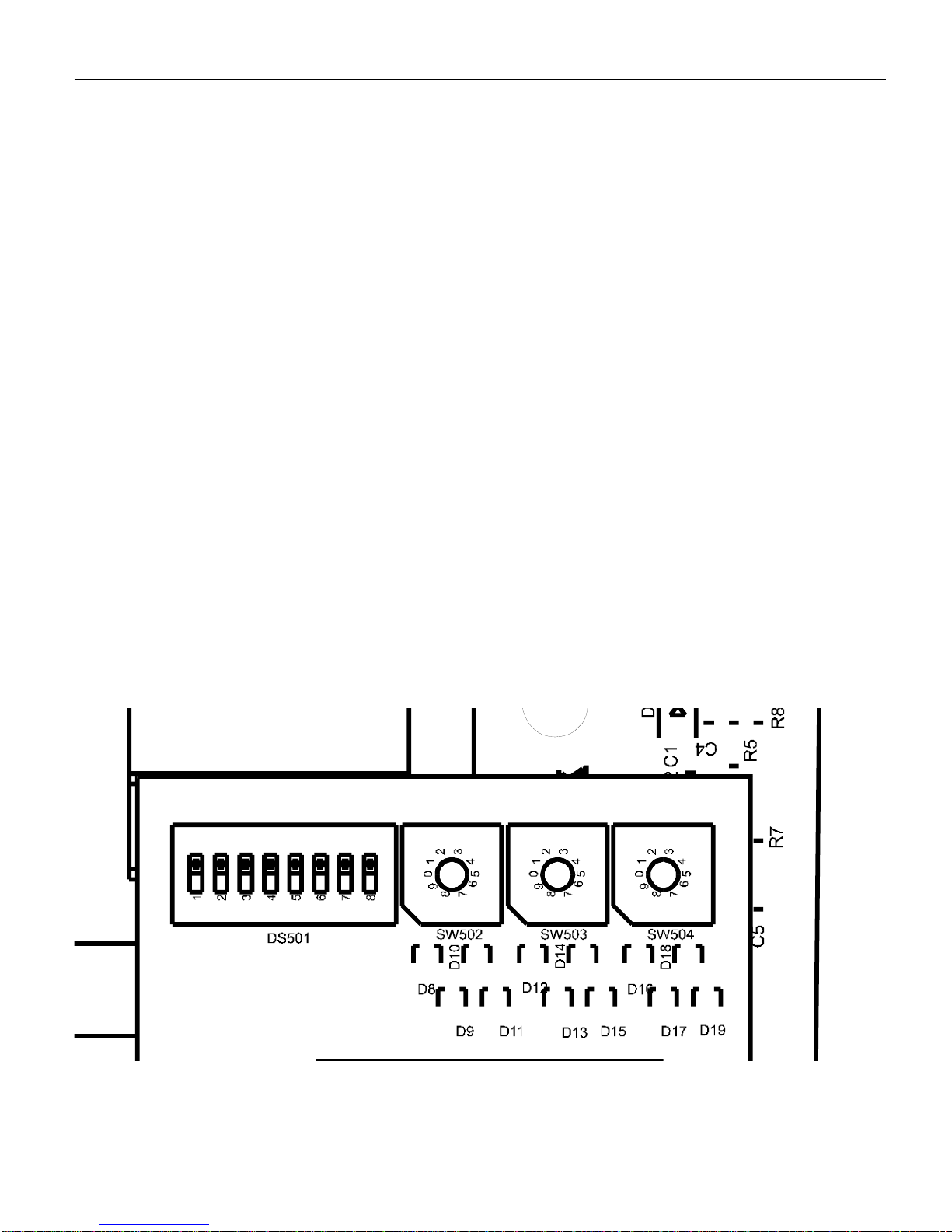
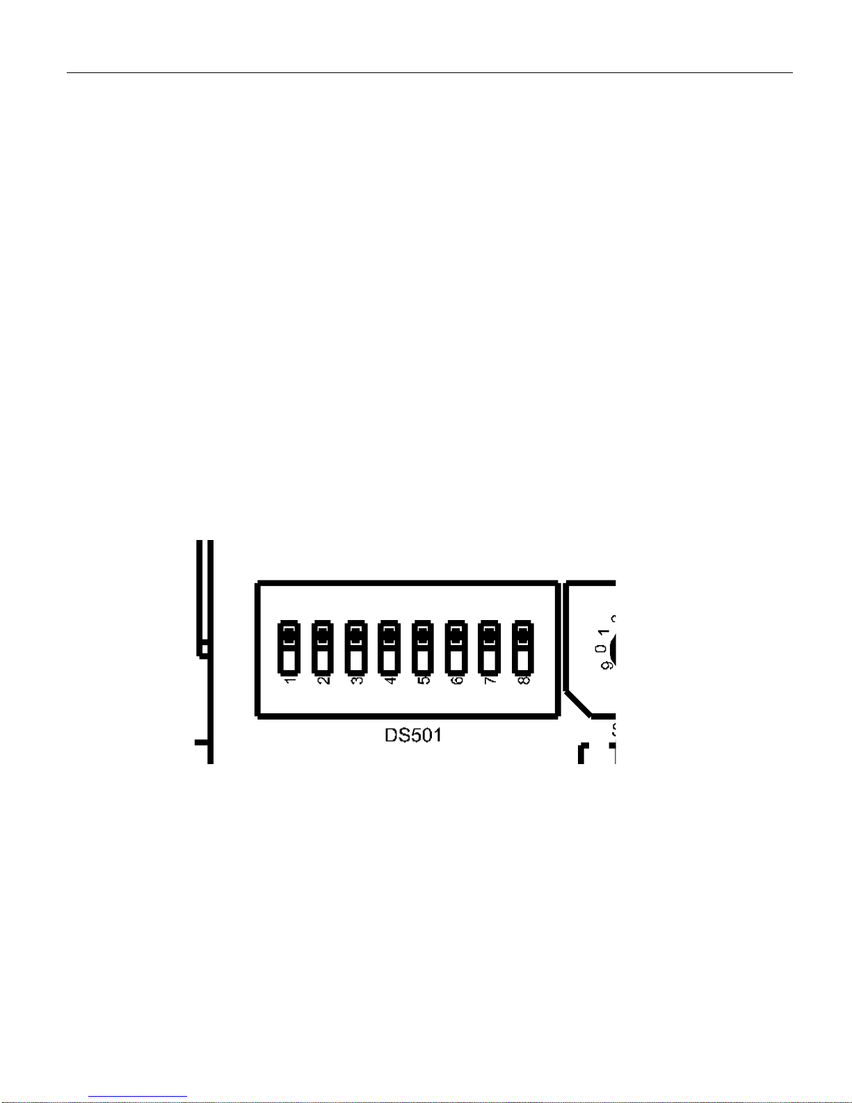
For access to the programming switches, remove the two
screws holding the rear cover to the case and remove the
cover. The switches are illustrated in Figure 5.
11
Figure 5. VT8 Programming Switches
250-0293.qxd 4/13/00 9:40 AM Page 11
Programming12
DIP switches
To change the position of the DIP switches use a small
screwdriver to push each DIP switch to the desired position.
The DIP switch block has a similar construction style to one
shown below (Figure 11).
Figure 6. VT8 DIP Switches
250-0293.qxd 4/13/00 9:40 AM Page 12
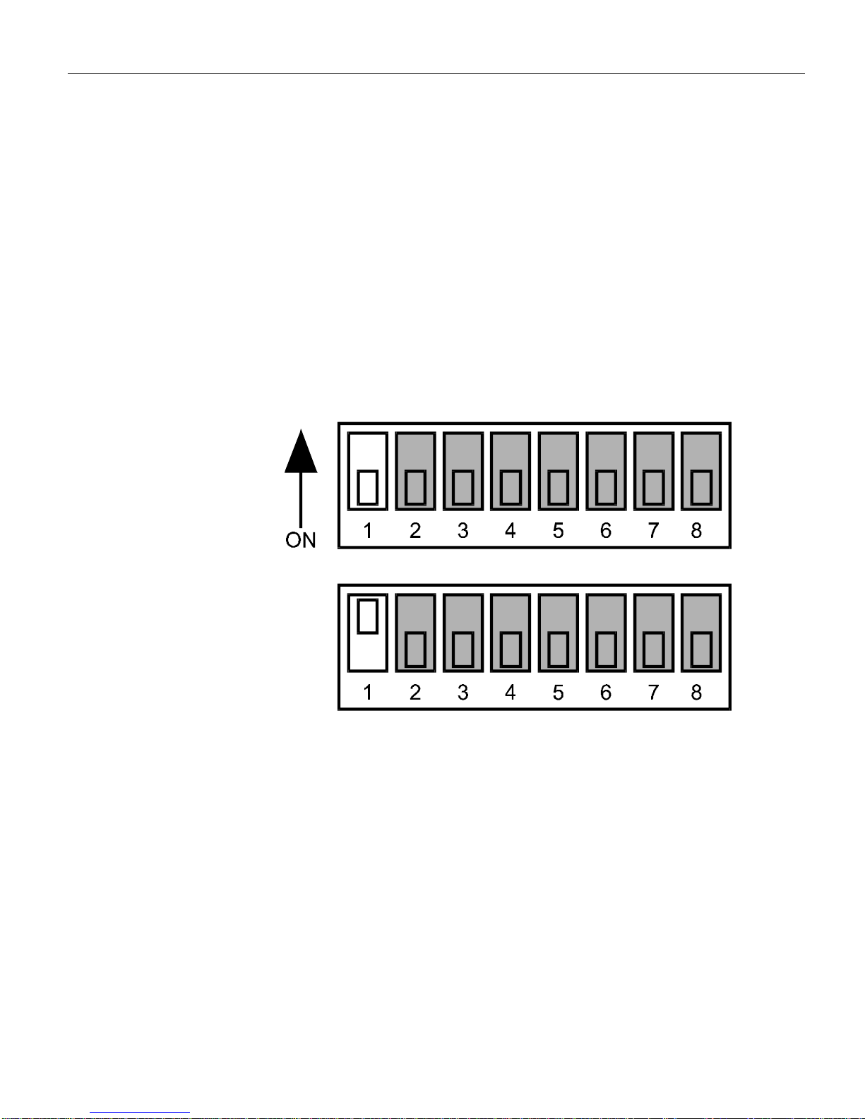
Encoder power supply (DIP switch #1)
DIP switch 1 determines the VT8 power supply output to an
external encoder. Set DIP switch to OFF for +5 VDC or ON
for +12 VDC to power an optical encoder. For accuracy and
current output of this power supply see the specifications on
page 1.
13
Programming
+5 VDC
ENCODER
VOLTAGE
12 VDC
ENCODER
VOLTAGE
Figure 7. Encoder Power Supply DIP Switch
250-0293.qxd 4/13/00 9:40 AM Page 13
Programming14
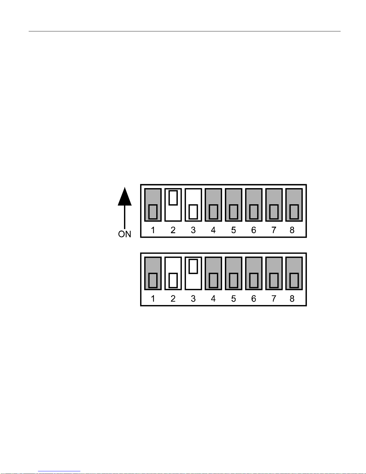
Feedback select (DIP switches 2 and 3)
DIP switches 2 and 3 are dependent upon which type of
feedback has been selected. See the table below for the
settings.
OPTICAL
ENCODER
FEEDBACK
MAGNETIC
PICKUP
FEEDBACK
Figure 8. Feedback Select DIP Switches
250-0293.qxd 4/13/00 9:40 AM Page 14
Table of contents
Other Minarik Music Equipment manuals


