MINATO 500 Series User manual

OPERATION
MANUAL
MODEL500
SERIES
PROGRAMMER
Revision
2016/09/29 Rev.1.00
2017/02/03 Rev.2.00
Corrected description of connected USB during hardware setup
(USB2.0->USB3.0)
2017/04/08 Rev.3.00
Corrected typographical error in the operation after power on.
2017/04/12 Rev.4.00
Added description of how to upgrade software version.
2017/06/16 Rev.5.00
Corrected Recommended PC requirements. Added specifications and
photos of M504,M508.
2017/09/22 Rev.6.00
Added about Protect function.
2018/05/09 Rev.7.00
Name change of company.
Added the note that project file created in M400 programmer can be
used.
2018/05/09 Rev.8.00
Name change of company.
Added the description of eMMC 4 sockets unit in Module chapter.
2018/02/15 Rev.9.00
Added the note about operation of module.
Added the description of new function and note about load file/save buffer.
2019/10/29 Rev.10.00
Added Windows10 to OS requirements.
2022/01/17 Rev.11.00
Added FPGA update behaviour.
2022/06/30 Rev.12.00
Change of business address.
Added note on Self test execution.

Preview
2
M500-011A-K6
Preview
Dear Customer,
We are pleasure to see you purchasing Minato Gang Programmer MODEL500 Series.
This manual explains how to use MODEL500 Series correctly, so please read this
manual before operation.
Register for Warranty
MINATO ADVANCED TECHNOLOGIES INC. will implement support for our
products, please register all the information on our web.
Before register please check below 3 items about the programmer:
MODEL
Serial Number (see Rear Panel)
Version (see operation manual CD-ROM)
The warranty does not apply to some problem, please read ”Warranty terms” for
details.
MINATO ADVANCED TECHNOLOGIES INC.
http://www.minatoat.co.jp

PC Requirements for control MODEL500
3
M500-011A-K6
PC Requirements for control MODEL500
OS requirements
Windows Vista
Windows 7 ( 32bit, 64bit )
Windows 8, 8.1 ( 32bit, 64bit )
Windows10
Recommended PC requirements
CPU 32bit(x86)or64bit(x64) 1GHz or Higher
If possible, dual core or higher performance CPU is
recommended.
RAM 1GB or Higher(32bit), 2GB or Higher(64bit)
Hard disk 50GB or Higher for OS/Application software +
maximum data file size to store
Interface USB2.0 or Higher
USB More than 1
CD Driver CD-ROM
The free space of Hard disk depends on the target device which should be
programmed. Please prepare enough space for large capacity device programming.
First time connecting M500 Series to PC, please read below notice items.
[Notice for first time connecting to PC ]

Simple Guide
4
M500-011A-K6
Simple Guide
Installation ・・・・・・ 27
Software ・・・・・・ 27
Hardware ・・・・・・ 30
Notice for first time connecting to PC ・・・・・・ 33
PC Requirements ・・・3
Outline ・・・15
Outline
Features
Specifications
Element & function ・・・16
Module & Adapter ・・・23
Outline ・・・35
Outline ・・・35
Start ・・・36
Description of the main screen
・・・38
Basic operation ・・・51
Description ・・・51
Select device ・・・52
COPY ・・・58
ERASE ・・・60
BLANK ・・・62
PROGRAM ・・・64
VERIFY ・・・66
CONT ・・・68
Contact Check, ID Check
・・・71
Protection ・・・72
Function ・・・73
Load file/save buffer ・・・74
Buffer Editor ・・・81
Project management ・・・97
Lot management ・・・99
Status of operation ・・・102
Auto start ・・・106
Setting of programmer ・・109
About operation ・・111
Quick start ・・・117
Trouble shooting ・・・119
Terminology ・・・128
Contacts ・・・132
Revision ・・・133
Preview
Hardware
Software
Reference

Warranty Terms
5
M500-011A-K6
MODEL500 Series Packing list
Before installing your programmer, please carefully check that your package include
all next mentioned parts. If you find any discrepancy or if any of these items are
damaged, please contact distributor or Minato directly.
[Packing list]
MODEL500 Series
(MODEL504*, MODEL508*, MODEL516)
Interface
(4 for MODEL504, 8 for MODEL508 and 16 for MODEL516)
Power Cable
USB Cable
CD (MODEL500 Series control software, USB driver, Operation manual
[ PROGRAMMER operation manual])
MODEL504 MODEL508
MODEL516

Warranty Terms
6
M500-011A-K6
Warranty Terms
Minato gives a guarantee on programmer for one-year from the date of purchase (Just
for customer who has registered their programmer). The warranty does not apply to
products on some conditions, so please read below contents.
Warranty Period
One-year from the date of purchase.
Warranty Items
1. Less than one-year after purchasing.
2. Having registered your programmer.
3. Does not caused by abnormal operation.
4. MODEL500 Series Hardware is defective.
5. This warranty is valid only in Japan.
Pay for repair
Even during warranty period, warranty is invalid for below items:
1. Programmer has not been registered.
2. Have not registered the full information.
3. Damage caused by inappropriate use.
4. Damage caused by natural disaster.
Exempt of Warranty
Minato is not liable for:
1. IC and data to program.
2. Direct and indirect cost due to damage of programmer.
3. Programmer be used oversea (not in Japan).
4. Damage caused by using third party items(example: adapter, software).
5. Repair or modification by unauthorized party.
6. Damage caused by inappropriate use or handling.
7. Version up of MODEL500 Series.
Version-up for new device is not free. Please see ”maintainance of M500 Series” for
details.

Warranty Terms
7
M500-011A-K6
Special notes
1. Register will be ok after you sending all the information to Minato.
2. You should pay for the transportation fee from you to Mianto.
3. Please keep the box provided by Minato which can be reused while transportation
for repair. Please make sure the package is strong, otherwise you should pay for
the damage of programmer.
4. Minato will pay for the transportation fee after repairing.
5. This manual will be updated without notice.
6. In case of any incomprehension, please contact us.

Maintainance of M400 Series
8
M500-011A-K6
Maintainance of M500 Series
To ensure that your programmer continue to meet good performance and your request.
Warranty of M500 Series
One-year warranty from the date of purchase from Minato (Just for customer who has
registered their programmer). Please see “warranty terms“ for details.
Version up for M500(IC/software support)
New IC can be supported by updating the software of programmer. Version-up to add
new IC support is not free of charge even within warranty period.
* If there’s defective of our software, the update is free.
Calibration
M500 Series is mass production equipment, please maintain the programmer every
day and calibrate the programmer per year.
About repair, calibration and version up
Minato does not provide on-the-spot service no matter free charge or not. And we can
not provide spare programmer, please understand. Customer should pay for the
transportation fee from you to minato for repair, calibration and version up. Minato
will bear the transportation cost for return.
Contents
9
M500-011A-K6
Safety Precaution
Warning and Cautions
This operation manual includes safety precautions for safely use M500 Series
programmer. To prevent the operator or others people from injury and property
damage, please following below pictographs to operate.
Before reading this manual, fully understand these pictographs and the meanings.
Keep this manual at hand and refer to it while necessary.
Explanation of Pictographs
Warning
Indicates a potential hazardous situation in which
the operator would be killed or seriously injured
unless this precaution is observed.
Cautions
Indicates a potential situation in which the operator
would be injured or property would be damaged
unless this precaution is observed.
Contents
10
M500-011A-K6
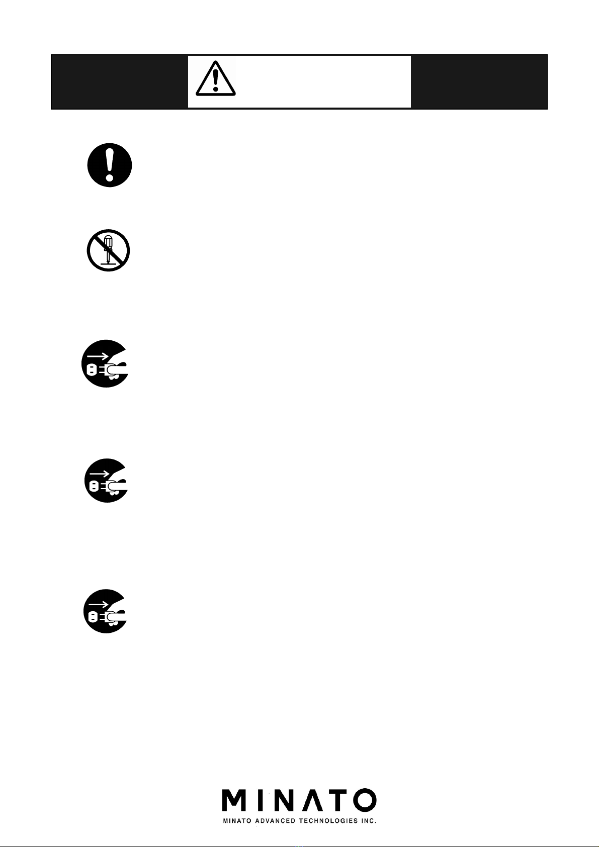
WARNING
Making sure to follow warnings and cautions while operation the
programmer.
Do not disassemble or modify the programmer. It may cause a
fire or electric shock.
When finding a smoke, abnormal smell or sound, please remove
the power plug immediately. Otherwise it may cause a fire or
electric shock due to short-circuit.
If the programmer is dropped or shocked, please remove the
power plug immediately. Otherwise it may cause a fire or electric
shock due to short-circuit.
Consult with Minato or distributor.
If any liquid or foreign matter enters the programmer, please
remove the power plug immediately. Otherwise it maybe will be
caused a fire or electric shock due to short-circuit.
Consult with Minato or distributor.
Unplug Power
Cord
Unplug Power
Cord
Unplug Power
Cord
Do Not
Disassembled
Compulsion
Compulsion

Contents
11
M500-011A-K6
Cautions
The operator should fully understand the manual before operation.
Miss operation may damage the programmer or ICs.
Before touching the programmer, please touch a nearby large metal
to remove static electricity from your body.
Static electricity may damage the programmer or ICs.
Please clean the surfaces, the socket and the air filter screen of
programmer.
Dusts may cause a fire or breakdown, so please clean them at regular
intervals.
Do not program IC when Empty Socket (red LED) is indicated. It
means the contact check is failed and programming maybe damage
the ICs or programmer caused by the heat.
Please confirm the CheckSum for PASS/FAIL.
Avoiding NG ICs are mixed with OK ICs.
Compulsion
Compulsion
Compulsion
Compulsion
Compulsion

Contents
12
M500-011A-K6
Caution for accessories
Standard power cable complies with Japanese regulation.
If you will use this programmer in others country, please follow the
local safety Standard.
Before you execute Programmer Self test, please remove device and
adapter from socket unit.
Otherwise device or adapter might be damaged.
Compulsion
Compulsion

Contents
13
M500-011A-K6
Contents
Contents
PREVIEW ........................................................................................................................................ 2
PC REQUIREMENTS FOR CONTROL MODEL500 .................................................................... 3
SIMPLE GUIDE .............................................................................................................................. 4
MODEL500 SERIES PACKING LIST ............................................................................................ 5
WARRANTY TERMS ...................................................................................................................... 6
Warranty Period .............................................................................................................................. 6
Warranty Items ............................................................................................................................. 6
Pay for repair ................................................................................................................................ 6
Exempt of Warranty ..................................................................................................................... 6
Special notes.................................................................................................................................. 7
MAINTAINANCE OF M500 SERIES ............................................................................................. 8
Warranty of M500 Series .............................................................................................................. 8
Version up for M500(IC/software support) ................................................................................... 8
Calibration .................................................................................................................................... 8
About repair, calibration and version up ....................................................................................... 8
SAFETY PRECAUTION .................................................................................................................
Warning and Cautions ..................................................................................................................
Explanation of Pictographs ...........................................................................................................
CONTENTS ................................................................................................................................... 12
OUTLINE ...................................................................................................................................... 15
Outline ........................................................................................................................................ 15
Features ...................................................................................................................................... 15
Specification ................................................................................................................................ 15
MODEL500 SERIES ELEMENT AND FUNCTION ................................................................... 16
MODULE POSITION ................................................................................................................... 17
REAR PANEL ............................................................................................................................... 18
MODULE ....................................................................................................................................... 20
OPTIONAL ITEMS ....................................................................................................................... 22
ABOUT VARIOUS ADAPTERS ................................................................................................... 23
Various adapters ......................................................................................................................... 23
ABOUT ADAPTER ........................................................................................................................ 24
INSTALLATION ........................................................................................................................... 27
Installation of Software ............................................................................................................... 27
Installation for Hardware ............................................................................................................ 30

Contents
14
M500-011A-K6
NOTICE FOR FIRST TIME CONNECTING TO PC ................................................................... 33
MODEL500 SERIES CONTROL SOFTWARE ( UNIVERSAL CONTROL PROGRAM ) .......... 35
Outline ........................................................................................................................................ 35
Start Running the Universal Control Program ............................................................................ 36
Description of the main screen ..................................................................................................... 38
BASIC OPERATION ..................................................................................................................... 51
Select Device ............................................................................................................................... 52
COPY ......................................................................................................................................... 58
ERASE ....................................................................................................................................... 60
BLANK ....................................................................................................................................... 62
PROGRAM ................................................................................................................................ 64
VERIFY ...................................................................................................................................... 66
CONT ......................................................................................................................................... 68
Contact check, ID check .............................................................................................................. 71
Protect ........................................................................................................................................ 72
FUNCTION DESCRIPTION ........................................................................................................ 73
Load file ...................................................................................................................................... 74
Save buffer .................................................................................................................................. 7
Buffer Editor (Edit) ..................................................................................................................... 81
Project Management ................................................................................................................... 7
Lot Management .........................................................................................................................
Operation Status ....................................................................................................................... 102
Auto Start ................................................................................................................................. 106
PROGRAMMER SETTING ........................................................................................................ 10
Buffer Setting of PC .................................................................................................................. 110
OPERATION ............................................................................................................................... 111
QUICK START ............................................................................................................................ 117
TROUBLESHOOTING ............................................................................................................... 11
TERMINOLOGY ......................................................................................................................... 128
CONTACTS ................................................................................................................................. 132
REVISION ................................................................................................................................... 133

Outline
15
M500-011A-K6
Outline
Outline
M500 Series are Gang Programmer which can be controlled by PC (windows OS)
software through USB Port. It is also can be used independently as program files has
been saved in the independent version. (The independent version hasn't been launched
on market.)
M500 Series are equipped with 128GByte (1024Gbit) Buffer Memory and can flexibly
support advanced PROM IC devices with large capacity, specially designed for small
scale production and circuit design technicians,
This series product has high reliability and high-speed action and provides high
performance for mass programming.
Features
Improved for Operating environment.
High programming speed.
Equipped with 128Gbyte Buffer Memory (SSD).
Supporting various devices.
Sharing the adapters with another MODEL.
Specification
Item
MODEL504*
MODEL508*
MODEL516
Note
Simultaneous
progra
mming
4 8 16
Buffer Memory
1024Gbit
1024Gbit
1024Gbit
Interface
USB
USB
USB
Rev.2.0
or
Rev.
3
.0
Operating
Temperature
5~35 [℃] 5~35 [℃] 5~35 [℃]
Operating Humidity 20~80%
(No condensation)
20~80%
(No condensation)
20~80%
(No condensation)
Power AC100~240 [V]
50~60 [Hz]
AC100~240 [V]
50~60 [Hz]
AC100~240 [V]
50~60 [Hz]
Power dissipation
100
[VA] (max.)
20
0[VA] (
max.)
4
00[VA] (max.)
Fuse
3.
36
[A]
6.62
[A]
14.7
[A]
Size 235(W)x240(D)x
130(H)
[mm]
375(W)x240(D)x
130(H)
[mm]
375(W)x380(D)x
130(H)
[m
m]
hight includes
socketunit
Weight
3.5
[kg]
5.0
[kg]
9.0 [kg]

M400 Series Element and Function
16
M500-011A-K6
MODEL500 Series Element and Function
In order to operate MODEL500 Series properly, please understand the function of
each part and its name.The details are described in following pages.
When used, MODEL 500 series of products shall be accompanied by dedicated
control software and socket unit. Please note that the startup would fail if software
other than special control software is used. For further information about detailed
description of special control software, please refer to the Operation Instructions for
“Control Software of Model 500 Series” in this manual. Please refer to “About socket
unit” for detailed description of socket unit.
Example) MODEL516
STATUS STATUS
MINATO
PASS FAIL PASS FAIL PASS FAIL PASS FA IL PASS FAIL PASS FAIL PASS FAIL PASS FAIL
PASS FAIL PASS FAIL PASS FAIL PASS FA IL PASS FAIL PASS FAIL PASS FAIL PASS FAIL
START
SATA1 SATA2 SATA3 SATA4 SATA5 SATA6 SATA7 SATA8
1 2 3 4 5 6 7 8
SATA9 SATA10 SATA11 SATA12 SATA13 SATA14 SATA15 SATA16
9 10 11 12 13 14 15 16
STATUS
MINATO
High-speed serial connection (SATA)
For SATA and IC connections.
Module Position
Start
Status LED
Rear Panel
High-spee
d serial
connection
(SATA)

Module Position
17
M500-011A-K6
Module Position
Example) MODEL516
STATUS STATUS
MINATO
PASS FAIL PASS FAIL PASS FAIL PASS FA IL PASS FAIL PASS FAIL PASS FAIL PASS FAIL
PASS FAIL PASS FAIL PASS FAIL PASS FA IL PASS FAIL PASS FAIL PASS FAIL PASS FAIL
START
SATA1 SATA2 SATA3 SATA4 SATA5 SATA6 SATA7 SATA8
1 2 3 4 5 6 7 8
SATA9 SATA10 SATA11 SATA12 SATA13 SATA14 SATA15 SATA16
9 10 11 12 13 14 15 16
STATUS
MINATO
SOCKET Number
Each SOCKET has a corresponding number. And we use “#+number” to express it in
this manual.
Example)
SOCKET 2 is described as ”#2”
Socket LED(Indicating PASS/FAIL)
Different color means the operating result.
PASS Green
FAIL Red
Side Panel
18
M500-011A-K6
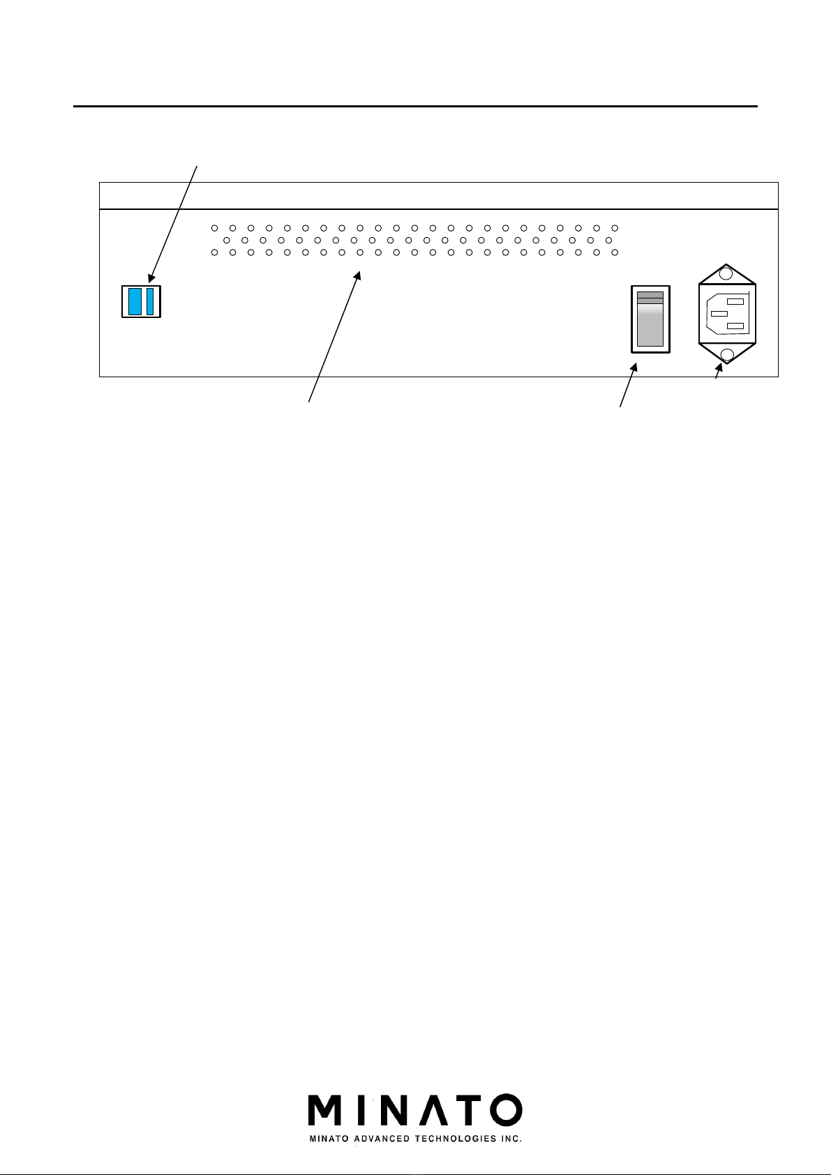
Rear Panel
Power Connector
AC power supply connector.
Power Switch
Power switch
USB Connector
USB connector
INPUT:100V-240V
4.0A
50-60Hz
OFF
ON
POWERUSB
WARNING!
This is class A product.
In a domestic environment,
This product may cause
radio interference
in which case the user
may be required to take
adequate measures.
+
+
Power
Connector
Power Switch
Air Vent
USB connector

Rear Panel
19
M500-011A-K6
Side Panel
Air vent
Air vent is designed for the external air sucked for cooling the interior of MODEL500
series. Please keep the vent unblocked. Please use dust collector etc. to remove
apparent dust (if any) in air filter.
Serial Number
Each programmer has a unique Serial Number and it will be required for service.
Revision Number
Revision Number of Hardware and it will be required for service.
Serial number
Revi
sion number
Air vent

Side Panel
20
M500-011A-K6
Module
Installed on PC and equipped with IC or adapter.
The PC is equipped with a module with 48pin socket.
Pay attention to the following content when installing the module on PC.
Please power off before removal or insertion of module to prevent internal fuse failure.
Please align with the module installation frame of PC; otherwise, the connector terminal at the
PC side may be damaged.
Do not insert the module sideways. Be sure to insert vertically.
PASS FAIL PASS FAIL
PASS/FAIL LED
48pin socket
Module installation frame
○×
This manual suits for next models
3
Table of contents
Other MINATO Motherboard manuals


Popular Motherboard manuals by other brands

ON Semiconductor
ON Semiconductor MT9M114EBLSTCZH3-GEVB user manual

Intel
Intel BLKDG33TLM - G33 Express Socket775 mATX... Product guide

Wiznet
Wiznet WizFi250 quick start guide

DFI
DFI LANPARTY UT X58 t3eh8 user manual

ASROCK
ASROCK B650M-H/M.2+ user manual

Intel
Intel G31 EXPRESS CHIPSET SPECIFICAT user manual


 user manual")


