QDI PlatiniX P8/333 Series User manual

Chapter 1
Introduction .................................................................... 1
Key Features ................................................................. 2
Chapter 2
Installation Instructions................................................... 5
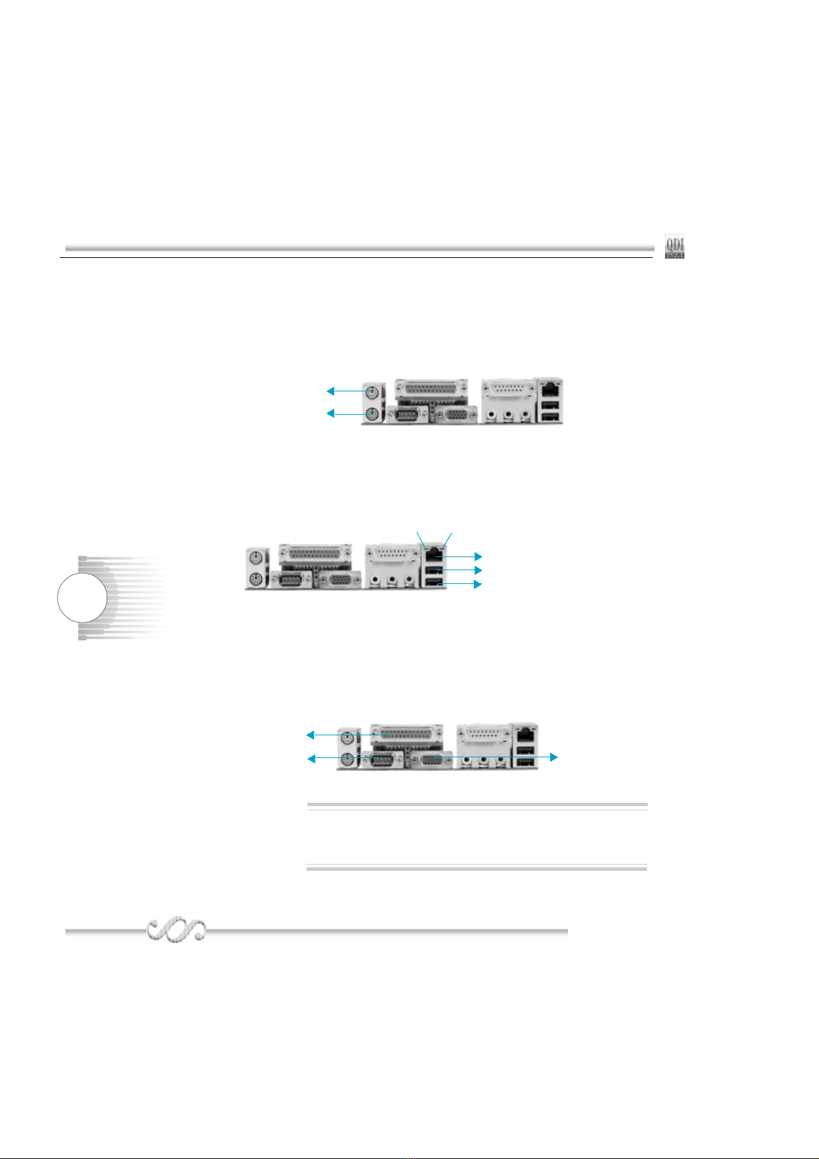
1. External Connectors ..................................................6
PS/2 Keyboard /Mouse Connector ................................ 6
USB1, USB2 and LAN Connectors ................................. 6
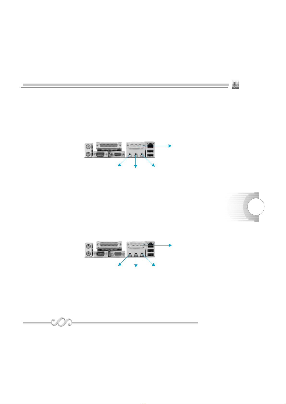
Parallel Port, Serial Port Connectors ............................. 6
Line-in jack, Mic-in jack, Speaker-out jack and
MIDI/Joystick Connector ................................................. 7
6-Channel Audio ............................................................ 7
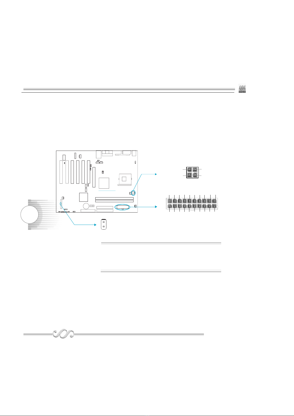
ATX 12V Power Supply Connectors & Power Switch ..... 8
Hard Disk LED Connector ( HD_LED ) .......................... 8
Reset Switch ( RESET ) ................................................. 8
Speaker Connector ( SPEAKER ) .................................. 9
Power LED Connector( PWR_LED ) .............................. 9
Green LED Connector( GREEN_LED ) ......................... 9
ACPI LED Connector( ACPI_LED ) ................................ 9
Hardware Green Connector ( SLEEP SW ) ................... 9
Key Lock Connector( KEYLK )....................................... 9
COM2,USB3 ,USB4 Connector ...................................... 10
Infrared Header ( IrDA ) ................................................. 10
Fan Connectors( CPU_FAN , SYS_FAN, PWR_FAN ) ... 11
Intruder Detect Switch( JINTR ) ...................................... 11
Wake-Up On LAN ( WOL ) ............................................. 12
Wake-Up On Internal Modem ( WOM ) .......................... 12
Audio Connectors (CD_IN1, CD_IN2, MODEM_IN ) ....... 13
4-pin SMBus Connector( SMBUS ) ................................ 13
Diagnosis LED ............................................................... 14
Hyper-Threading Detector ............................................. 14
Audio Interface ............................................................... 15
SPDIF Connector ...........................................................16
Chassis Security Switch(CHSSEC) ................................ 16
2. Jumper Settings .................................................. ..... 17

Wake-up function(JUSB, JFUSB)...........................................17
Overclocking Jumper Setting(JFS0,JFS1)..............................18
BIOS-Protection Jumper( BIOS_WP ).................................... 19
Enable keyboard password power-on function(JKB)..............20
Clear CMOS(CLR_CMOS).....................................................21
Chapter 3
BIOS Description....................................................................23
AWDFLASH.EXE .................................................................. 24
AWARD BIOS Description..................................................... 25
QDI Innovation features.........................................................29
Advanced BIOS Features Setup............................................31
Advanced Chipset Features Setup........................................33
Power Management Setup.....................................................35
PnP/PCI Configurations Setup...............................................38
Integrated Peripherals........................................................... 39
PC Health Status....................................................................42
Password Setting...................................................................44
Boot with BIOS defaults......................................................... 44
Appendix
QDI Driver CD....................................................................... 45
Norton AntiVirus.................................................................... 45
LogoEasyII.............................................................................46
BIOS-ProtectEasy..................................................................47
RecoveryEasyII......................................................................48
SpeedEasyII...........................................................................53
BootEasy............................................................................... 54
StepEasyII..............................................................................55
BootEasy(German)................................................................57
Platinix2E/333(Spanish)......................................................... 58
Platinix2E/333(French).......................................................... 61
Platinix2E/333(Italian)............................................................ 65
Using 4/6-Channel Audio.......................................................68
Layout

1
PlatiniX 8/333PlatiniX 8/333
PlatiniX 8/333
Chapter 1Chapter 1
Chapter 1Chapter 1
Chapter 1
Chapter 1
Introduction
P8/333 series of mainboards utilize Intel® 845GE chipset
consisting of two components: the Intel 845GE Graphics
Memory Controller Hub(GMCH) and the I/O Controller
Hub4(ICH4), providing a fully compatible, high performance
and cost-effective ATX platform. The new integrated
technologies, together with AC’97 audio(2/6-channel), 6
USB , and ATA100/66/33, give customers an advanced, mul-
timedia solution at reasonable price. It provides 400/533MHz
host bus speed to support Intel®Pentium 4 socket 478 pro-
cessors and the DDR200/266/333 memory. It also provides
advanced features such as Wake up by USB devices, Wake-
on-LAN, Wake-on-Modem, ACPI, CPU overheat triple
protection, and Keyboard Password Power-on functions.
Suspending to RAM, the optimal implementation of the Ad-
vanced Configuration and Power Interface (ACPI) specifica-
tion, makes the PC’s power consumption drop to the lowest
possible level and enable quick wakeup.

2
IntroductionIntroduction
Introduction
QDIQDI
QDIQDI
QDI
Form factor
ATX form factor of 305mm x 232mm
Microprocessor
Supports Intel® Pentium 4 (Hyper-Threading) socket 478 processors
Supports Intel® Pentium 4 (Willamette) socket 478 processors at 1.8/1.9/2.0GHz
Supports Intel® Pentium 4 (Northwood) socket 478 processors at 1.8/2.0/2.2/2.26/2.4/2.53/2.66
/2.8/3.06GHz
Supports 400/533MHz host bus speed
System memory
Supports DDR200/266/333 SDRAM
Supports 64/128/256/512Mb technology up to 2GB
Provides two 184-pin DDR SDRAM interfaces
Onboard IDE
Supports Independent timing of up to 4 drives
Supports Ultra ATA 33/66/100, PIO mode
Two fast IDE interfaces supporting four IDE devices including IDE hard disks and CD ROM
drives
Onboard LAN(Available on -L, -AL, -6AL)(optional)
10/100 Mbit/sec Ethernet support (Intel82562 chip)
1000 Mbit/sec Ethernet support (Intel82540 chip)
10/100/1000M LAN interface built-in on board
USB 2.0/1.0
USB 2.0 compliant, operates at 480Mbps, about 40X times faster than USB 1.1 which cur-
rently works at a snails pace of just 12Mbps
Provides 6 USB 2.0/1.0 ports
Onboard I/O
One floppy port supporting up to two 3.5″or 5.25″floppy drives with 360K/720K/1.2M/1.44M
/2.88M format
Two high speed 16550 compatible COMs with 16 byte send/receive FIFO (COM1 on back panel,
COM2 on header with optional cable)
One parallel port supports SPP/EPP/ECP mode
Supports PS/2 mouse and PS/2 keyboard
Provides one IrDA connector
All I/O ports can be enabled/disabled in the BIOS setup
Key Features

3
PlatiniX 8/333PlatiniX 8/333
PlatiniX 8/333
Chapter 1Chapter 1
Chapter 1Chapter 1
Chapter 1
Onboard Audio(available on -A/-AL mainboard)
AC’97 2.2 Specification Compliant
Provides onboard Line-in Jack, Microphone-in Jack, Speaker-out Jack and MIDI/Joystick
Connector
6-channel Onboard Audio(available on -6A/-6AL mainboard)
AC’97 2.2 Specification Compliant
Provides Front left&right, Rear left&right/Line-in Jack and Center&Woofer/Microphone-in
Jack,which can be specified by software
Graphics Interface
Supports both 1.5V AGP 4X interface and intel AGP Digital Display(ADD) card
Integrated 2D/3D graphics accelerator, 256 bit graphics core, provides a VGA port
Advanced features
PCI 2.2 Specification Compliant
Provides Trend ChipAwayVirus On Guard
Supports Windows 98/2000/ME/XP soft-off
Supports Wake-on-LAN and Wake-on-Modem
Supports Keyboard Password Power-on function
Supports system monitoring(monitors CPU and system temperatures, system voltages,
fan speed)
Provides Diagnosis LEDs to indicate CPU, chipset, memory PCI device, clockgen and
video status during system booting up
Providing QDI innovations: RecoveryEasyII, BIOS-ProtectEasy, LogoEasyII, BootEasy,
StepEasyII, SpeedEasyII
CPU, AGP, DDR Voltage adjusting function with SpeedEasyII: Adjusting CPU, AGP and
DDR core voltage in BIOS to improve system stability and overclocking ability.(optional)
Supports CPU triple overheat protection
1. If the temperature of the CPU reachs the CPU Warning Temperature set in BIOS, the buzzer
will warn.
2. At the same time, the CPU THER-Throttling will be slowed down to the setpoint in BIOS.
3. If the temperature of the CPU reach the CPU Shutdown Temperature, the system will be
shutdown automatically under the ACPI OS and the data will be saved before.
(Reference to “PC Health Status” in BIOS)

4
IntroductionIntroduction
Introduction
QDIQDI
QDIQDI
QDI
Main Expansion Slots and Connectors
BIOS
Licensed advanced AWARD(Phoenix) BIOS, supports flash ROM, plug and play ready
Supports IDE CDROM/SCSI/USB boot up.
Green function
Supports ACPI (Advanced Configuration and Power Interface) and ODPM (OS Directed
Power Management)
Supports ACPI power status: S0 (full-on), S1 (power on suspend), S3 (suspend to RAM),
S4(suspend to Disk, depends on OS) and S5 (soft-off)
Slot/Port (Quantity) Description
PCI(6) PCI slots
IDE(2 ) IDE ports
FLOPPY(1) Floppy Drive port
DDR(2) DIMM socket
USB(6) USB connectors
AGP(1) AGP slot
LAN(1) (optional) LAN connector
COM(2) COM connectors
PARALLEL(1) Parallel connector
IrDA(1) IrDA connector
Our technology is subject to upgrade from time to time, the de-
scription and Interface for Easy technology in this manual are
only for your reference. Please download the latest BIOS or the
utility from the website.
Note:

5
PlatiniX 8/333PlatiniX 8/333
PlatiniX 8/333
Chapter 2Chapter 2
Chapter 2Chapter 2
Chapter 2
Installation Instructions
Chapter 2
This section covers External Connectors and Jumper
Settings. Refer to the mainboard layout chart for locations
of all jumpers, external connectors, slots and I/O ports.
Furthermore, this section lists all necessary connector pin
assignments for your reference. The particular state of the
jumpers, connectors and ports are illustrated in the follow-
ing figures. Before setting the jumpers or inserting these
connectors, please pay attention to the direction.

6
QDIQDI
QDIQDI
QDI
Installation InstrInstallation Instr
Installation Instructionuction
uctionuction
uction
External Connectors
PS/2 Keyboard/Mouse Connector
PS/2 keyboard connector is for the usage of PS/2 keyboard. If using a standard AT size
keyboard, an adapter should be used to fit this connector. PS/2 mouse connector is for the
usage of PS/2 mouse.
USB1, USB2 and LAN Connectors
(LAN connector is only available on -L/-AL/-6AL mainboard)
Two USB ports are for connecting USB devices. The RJ-45 connector is for onboard LAN.
PS/2 Mouse connector
PS/2 Keyboard connector
Parallel Port, Serial Port Connectors ( COM1 ) and VGA port
The parallel port connector can be connected to a parallel device such as a printer. The serial
port COM1 connector can be connected to a serial port device such as a serial port mouse. The
VGA port can be connected VGA connector. You can enable/disable them and choose the IRQ
or I/O address in “Integrated Peripherals” from AWARD BIOS SETUP.
Parallel Port
COM1
USB1
USB2
LAN (optional)
LINK ACTIVE
Be sure to unplug the AC power supply before adding or remov-
ing expansion cards or other system peripherals, otherwise your
mainboard and expansion cards might be seriously damaged.
Warning:
VGA

7
PlatiniX 8/333PlatiniX 8/333
PlatiniX 8/333
Chapter 2Chapter 2
Chapter 2Chapter 2
Chapter 2
Line-in jack, Microphone-in jack, Speaker-out jack and MIDI/Joystick Connector
(Available on -A/-AL/ mainboard)
The Line-in jack can be connected to devices such as a cassette or minidisc player to playback or
record. The Microphone-in jack can be connected to a microphone for voice input. The Speaker-out
jack allows you to connect speakers or headphones for audio output from the internal amplifier.The
MIDI/Joystick connector allows you to connect a game joystick or a MIDI device.
6-Channel Audio(Available on -6A,-6AL series mainboard)
This mainboard utilizes ALC650 chip providing 6-channel Audio, which consists of Front Left, Front
Right, Rear Left, Rear Right, Center and Woofer for a complete surround sound effect. When 6-
Channel audio is available, the front Left&Right jack can be connected to the Front speskers, the
Back Left&Right jack can be connected to the rear speakers and the Center&Woofer jack can be
connected to the center speaker and woofer.
Microphone function is offered by F_AUDIO Connector on the mainboard now.
If set 2-Channel Audio mode on -6A or -6AL mainboard, you can connect two speakers to the Front
Left&Right jack, at the same time use the Rear Left&Right jack as Line in jack, and use the
Center&Woofer jack as Microphone in jack.
MIDI/Joystick
Front left&right Rear
left&right
Center&Woofer
MIDI/Joystick
Speaker out Line in Microphone in

8
QDIQDI
QDIQDI
QDI
Installation InstrInstallation Instr
Installation Instructionuction
uctionuction
uction
Hard Disk LED Connector (HD_LED)
The connector connects to the case’s IDE indicator LED indicating the activity status of IDE
hard disk. The connector has an orientation. If one way doesn’t work, try the other way.
Reset Switch (RESET)
The connector connects to the case’s reset switch. Press the switch once, the system
resets.
ATX 12V Power Supply Connector & Power Switch (POWER SW)
The power switch (POWER SW) should be connected to a momentary switch. When powering
up your system, first turn on the mechanical switch of the power supply (if one is provided),
then push once the power switch. When powering off the system, you needn’t turn off the
mechanical switch, just push once the power switch. P8/333 series mainboard only support
ATX12V power.
If you change “Soft-off by PWR-BTTN” from default “Instant-off”
to “Delay 4 Sec” in the “POWER MANAGEMENT SETUP” sec-
tion of the BIOS, the power switch should be pressed for morethan
4 seconds before the system powers down.
POWER SW
12V
12V
GND
GND
+12V Power Supply Connector
1
ATX Power Supply Connector
20
1
12V
5VSB
5V
GND3.3V GND 5V GND PS-OK3.3V
5V5V
-5VGNDPS-ON-12V3.3V GND GND GND
1
Note:

9
PlatiniX 8/333PlatiniX 8/333
PlatiniX 8/333
Chapter 2Chapter 2
Chapter 2Chapter 2
Chapter 2
Speaker Connector (SPEAKER)
The connector can be connected to the speaker on the case.
Power LED Connector (PWR_LED)
When the system is in S0 status, the LED is on. When the system is in S1 status, the LED
is blink; When the system is in S3,S4, S5 status, the LED is off. The connector has an
orientation.
GREEN LED Connector (GREEN_LED)
When the system is in S0,S1,S4 ,S5 status, the LED is off,When the system is in S3 status,
the LED is on.
ACPI LED Connector (ACPI_LED)
The ACPI LED is a dual-color light with three pins. Pin1and Pin2 drive different color lights.
If Pin1 drives the orange light , then, Pin2 drives the green light, the following status will
come out. When the system is in S0 status, the LED is green on. When the system is in S1
status, the LED is green blink. When the system is in S3 status, the LED is orange on.
When the system is in S4, S5 status, the LED is off.
Hardware Green Connector (SLEEP SW)
Push once the switch connected to this header, the system enters suspend mode.
Key Lock Connector (KEYLK)
The connector can be connected to the keyboard lock switch on the case for locking the
keyboard.
SPEAKER RESET GREEN_LED KEYLK
PWR_LEDACPI_LED
HD_LED
SPEAKER RESET GREEN_LEDKEYLK
ACPI_LED SLEEP
SW PWR_LED
HDD LED(+) HDD LED(-)
ORANGE(-)
GREEN(-)
LED+
POWER
GND
EMPTY
EMPTY
SLEEP
GND
LED+
LED-
LED- KEYLOCK
GND
LED-
LED-
LED+
EMPTY
GND
RESET
SPKDATA
NC
GND
VCC
POWER
SW
POWER
SW
SLEEP
SW

10
QDIQDI
QDIQDI
QDI
Installation InstrInstallation Instr
Installation Instructionuction
uctionuction
uction
USB3 ;USB4;Serial Port Connector(COM2)
Besides USB1,2 on the back panel, P8/333 series of mainboards also have two 8-pin headers
on board which may connect to front panel USB cable( optional ) to provide additional four USB
ports. The serial port COM2 is not available on the back panel. Therefore, we provide a 9-pin
header.
Infrared Header (IrDA)
This connector supports wireless transmitting and receiving device. Before using this func-
tion, configure the settings for IR Address, IR Mode and IR IRQ from the “INTEGRATED
PERIPHERALS” section of the CMOS SETUP.
USB3
USB4
COM2
+5V
D5+
D5-
NC
GND
GND
NC
D6+
D6-
+5V
IrDA
1
VCC IRRX
GND
IRTX
NC
1
+5V
D3+
D3-
NC
GND
GND
NC
D4+
D4-
+5V
1
DCD
GND
SOUT-
RTS
RI
SIN
NC
DSR
CTS
DTR

11
PlatiniX 8/333PlatiniX 8/333
PlatiniX 8/333
Chapter 2Chapter 2
Chapter 2Chapter 2
Chapter 2
Fan Connectors (PWR_FAN, CPU_FAN, SYS_FAN(optional))
The fan speed of these three fans can be detected and viewed in “PC Health” section of the
CMOS SETUP.
Intruder Detect Switch(JINTR)(Reserved)
The connector connects to the chassis security switch on the case. The system can detect
the chassis intrusion through the status of this connector. If the connector has been closed
once, the system will send a message over the network to alert the network manager through
the on board LAN controller within ICH4.
SYS_FAN
SENSE
+12V
GND
+12V
CPU_FAN
SENSE
GND
PWR_FAN
+12V
GND
SENSE
JINTR
GND
Indicate signal
1

12
QDIQDI
QDIQDI
QDI
Installation InstrInstallation Instr
Installation Instructionuction
uctionuction
uction
Wake-Up On LAN (WOL)
Through the Wake-Up On LAN function, a wake event occurring from the network can
wake up the system. If this function is to be used, please be sure an ATX12V power supply
and a LAN adapter which supports this function are used. Then connect this header to the
relevant connector on the LAN adapter, set “Power on by Ring/LAN” as Enabled in the
“POWER MANAGEMENT SETUP” section of the CMOS SETUP. Save and exit, then boot
the operating system once to make sure this function takes effect.
Wake-Up On Internal Modem (WOM)
Through this function, the system which is in the suspend or soft-off status can be waked up
by a ring signal received from the internal modem. When this function is used, be sure an
internal modem card which supports this function is used. Then connect this header to the
relevant connector on the modem card, set “Power on by Ring/LAN” as Enabled in the
“Power Management Setup” section of the CMOS SETUP. Save and exit, then boot the
operating system once to make sure this function takes effect.
Signal for waking up
WOL +5V standby
GND
Signal for waking up
WOM +5V standby
GND
1

13
PlatiniX 8/333PlatiniX 8/333
PlatiniX 8/333
Chapter 2Chapter 2
Chapter 2Chapter 2
Chapter 2
Audio Connectors (CD_IN 1, CD_IN 2(optional),MODEM_IN)
(Available on -A/-6A/-AL/-6AL mainboard)
CD_IN 1,and CD_IN 2 are Sony standard CD audio connectors, they both can be connected to a
CD-ROM drive through a CD audio cable. The MODEM connector allows the onboard audio to
interface with a voice modem card with a similar connector. It allows connecting the mono_in
(such as a phone) or mono_out (such as a speaker) between the onboard audio and the voice
modem card.
4-pin SMBus Connector(SMBUS)
This connector allows you to connect SMBus devices. SMBus devices communicate through the
SMBus with a SMBus host and/or other SMBus devices. The SMBus or System Management Bus
is a specific implementation of I2C bus, which is a multi-master bus, that is, multiple devices can
be connected to the same bus and each one can act as a master by initiating data transfer.
CD_IN 1
CD_IN 2
MODEM_IN
SMBUS
1
SMBDATA
SMBCLK
5VSB
GND
Phone-In (from Modem)
GND
Mono-Out (to Modem)
CD Right Channel
Common
CD Left Channel
CD Right Channel
Common
CD Left Channel

14
QDIQDI
QDIQDI
QDI
Installation InstrInstallation Instr
Installation Instructionuction
uctionuction
uction
Diagnosis LED(optional)
During the POST , the LED1~LED5 representing POST steps will light up in turn.
please refer to the following table to learn the POST status:
Hyper-Threading Detector(optional)
LED1 LED2 LED3 LED4 LED5 status
blink off off off off CPU damaged , BIOS chip absent or damaged
on off off off off system detect CPU and initialize chipset
off on off off off system detect memory
off off on off off system initialize PCI
off off off on off system initialize clockgen
off off off off on system detect Video and invokeVideoBIOS
During the POST,If use the CPU of Hyper-Threading and Hyper-Threading is enable in the BIOS,
the LEDs will light up in turn, then blink together.
LED1 LED2 LED3 LED4 LED5 status
blink off off off off CPU damaged , BIOS chip absent or damaged
on off off off off system detect CPU and initialize chipset
off on off off off system detect memory
off off on off off system initialize PCI
off off off on off system initialize clockgen
off off off off on system detect Video and invokeVideoBIOS
on on on on on Hyper-Threading OK
LED1
LED5
LED3 LED4
LED2

15
PlatiniX 8/333PlatiniX 8/333
PlatiniX 8/333
Chapter 2Chapter 2
Chapter 2Chapter 2
Chapter 2
Audio Interface(Optional)
The audio interface provides three kinds of audio output choices: the FrontAudio, the
RearAudio and the ActiveAudio. Their priority level is as sequence. When the FrontAudio is
available, the RearAudio and the ActiveAudio( in-case speakers ) will be cut off. When the
RearAudio is available, the ActiveAudio will be cut off. An onboard amplifier is provided for
the earphone. When the FrontAudio is absent, Pin11 and Pin12, Pin13 and Pin14 must be
short connected.
Pin
No.
Symbol Pin
No.
Symbol
1 Active LINE Out(R) 2 Active LINE Out(L)
3 GND (ALO) 4 GND (ALO)
5 GND(+12) 6 GND(+12)
7 +12V(1A) 8 (Cut away )
9 MIC 10 GND ( MIC )
11 Front LINE Out( R ) 12 LINE Next( R )
13 Front LINE Out( L ) 14 LINE Next( L )
15 GND (FLO) 16 (Cut away )
Speaker Out
Line in
Microphone in
Speaker
Earphone
F_AUDIO
(Audio Interface)
1
3
5
7
9
11
13
15
2
4
6
8
10
12
14
16

16
QDIQDI
QDIQDI
QDI
Installation InstrInstallation Instr
Installation Instructionuction
uctionuction
uction
Chassis Security Switch (CHSSEC)(optional)
The connector connects to the chassis security switch on the case. The system can detect
the chassis intrusion through the status of this connector. If the connector has been closed
once, the system will record the status and indicate the chassis has been opened. You can
monitor or check this information from some software.
SPDIF Connector(optional)
The SPDIF input allow your digital audio input from digital audio devices.(optional) The SPDIF
output is capable of providing digital audio data or compressed AC3 data to an external
Dolby digital decoder.
SPDIF
1GND
SPDIF out
GND
CHSSEC
1
GND
Indicate signal
SPDIF out
SPDIF in
+5V

17
PlatiniX 8/333PlatiniX 8/333
PlatiniX 8/333
Chapter 2Chapter 2
Chapter 2Chapter 2
Chapter 2
Jumper Settings
Jumpers are located on the mainboard, the clear CMOS jumper CLR_CMOS, enable key-
board password power-on function jumper JKB etc. Pin 1 for all jumpers are located on the
side with a thick white line (Pin1→), referring to the mainboard’s silkscreen.
Jumpers with three pins will be shown as to represent pin1 & pin2 (“1-2”) closed
and to represent pin2 & pin3 (“2-3”) closed.
Jumper Symbol Description Represent
1-21-2
1-21-2
1-2 set pin1 and pin2 closed
2-32-3
2-32-3
2-3 set pin2 and pin3 closed
close set the pins closed
open set the pins opened
Enable Front/Back Panel USB Device Wake-up Function (JFUSB/JUSB)
(optional)
The mainboard provides the advanced USB device wake-up function. The system can be
waked up from its power saving status including ACPI S3 by activating USB device. Before
using this function, set JFUSB/JUSB with pin1 & pin2 closed. Otherwise, set JFUSB/JUSB
with pin2 & pin3 closed for disabling. Furthermore, the item “Wake-Up From S3 by USB”in
Power Management Setup should also be set correspondingly to enable or disable this
function.
JUSB
JFUSB
Enable
Disable
Disable Enable
1
2
3
1
2
3
123 123

18
QDIQDI
QDIQDI
QDI
Installation InstrInstallation Instr
Installation Instructionuction
uctionuction
uction
Overclocking Jumper Setting (JFS0,JFS1)
Jumpers JFS0 and JFS1 provides users with CPU overclocking feature. The host bus speed
can be set as 100x4/133x4/200x4MHz or AUTO. If CPU FSB(front side bus) is set as auto,
the system detects the CPU FSB automatically. The table below is for your reference.
Whether or not your system can be overclocked depends on the capability of your processor
and memory. Whether the processor is bus ratio locked or unlocked should also be taken
into account. For bus ratio unlocked processor, this overclocking feature can be implemented
by setting FSB as 100x4/133x4/200x4MHz, meanwhile adjusting the bus ratio (multiplier) in
“QDI Innovation features” in AWARD BIOS CMOS Setup and memory.
You can also adjust the CPU frequency by running StepEasyII. We do not guarantee the
stability of the overclocking system.
JFS1
1
2
3
JFS0
1
2
3
Be sure your selection is right. CPU over speeding is dangerous! We
will not be responsible for any damages caused.
Warning:
“1-2”: pin1 & pin2 closed “2-3”: pin2 & pin3 closed
133x4MHz 200x4MHz
CPU FSB 100x4MHz
AUTO
OPEN OPEN
2-3
2-3
1-2
1-2
1-2
JFS0
JFS1
1-2
Table of contents
Other QDI Motherboard manuals

QDI
QDI K7VM400M Pro Series User manual

QDI
QDI Advance 5 User manual

QDI
QDI SynactiX 2EP User manual

QDI
QDI WinneX3E User manual

QDI
QDI Superb 4L User manual

QDI
QDI WinneX 3 User manual

QDI
QDI Legend-III P6I440LX/AV User manual

QDI
QDI GeniuX 4 User manual

QDI
QDI SynactiX 1E User manual

QDI
QDI K8N4 Series User manual

QDI
QDI P5I915PL User manual

QDI
QDI BrillianX 8V User manual

QDI
QDI P4I848P User manual

QDI
QDI Pentium P5I430TX/IIB TITANIUM IIB User manual

QDI
QDI P51437/250a User manual

QDI
QDI PlatiniX 7B User manual

QDI
QDI BrillianX 1S/2000 User manual

QDI
QDI ZillioX 9 User manual

QDI
QDI KinetiZ 7A User manual

QDI
QDI K8V800 User manual