MINDPRINT T.R.I.O. User manual

MANUAL
www.mindprint.com
MANUAL
1.0
DEUTSCH
ENGLISH

MindPrint
®
T.R.I.O.
Important:
Please read safety instructions
on page 50 - 51 before use!
Wichtig:
Bitte lesen Sie vor der Inbetriebnahme
die Sicherheitshinweise auf Seite 50!
Important :
Avant la mise en service, prière de lire
les consignes de sécurité à la page 51 !
Importante:
Prima di utilizzare lo strumento, leggere
attentamente gli avvisi di sicurezza su pagina 52!
Importante:
¡Antes de la puesta en servicio lea por favor
las indicaciones de seguridaden la página 52!

3
MindPrint
®
T.R.I.O.
ENGLISH
Welcome to MindPrint!
We’re delighted that you opted for T.R.I.O™! Please take the time to
read this manual. It offers detailed explanations on how to handle
T.R.I.O™, provides a wealth of helpful information, and reveals lots of
tips and tricks used by pros.
Recording is taking a turn towards total convenience, and a sea change
is sweeping over the audio workplace. Where yesterday a mondo
mixing console crowded your desktop, today a tiny laptop is perched in
its place. Where 19" racks with outboard effects and samplers/synths
once stood, you’ll now find a couple of CD-ROMs with plug-ins and
software synths. The future belongs to the mighty mite – a small yet
powerful setup that costs less, saves space, handles ergonomically, and
delivers high-end audio despite its diminutive size.
T.R.I.O™ is the nerve center of the “mixer-less” studio. It brings together
the three types of signal routing portals - inputs, outputs and interfa-
ces - to take the place of a mixer’s input ports and monitor section. And
it offers an IN/OUT interface to your DAW. When you make T.R.I.O™
part of you contemporary computer-based studio, you need no other
audio handling device.
Here’s wishing you tons of fun recording with T.R.I.O™!
The Philosophy Behind
T.R.I.O™
Before we get to it, allow us a few words on the philosophy behind the
T.R.I.O™: We made every effort to ensure this device’s functionality and
signal flow is easily understood and conveniently handled, even if you have
never dealt with mixers, microphone preamplifiers and compressors before:
The left side of the device handles input channels, amplifying signals and
porting them to the computer. Incoming signals returning the computer are
routed to the right side and bussed on to the monitoring circuits. Below
these sections at the center of the panel you’ll find monitor volume controls
for the input channels. You may be happy to learn that you’re dealing with a
zero latency monitor signal. On the bottom right, you’ll find a big and very
important knob. It determines master monitor volume.
WARRANTY
Please register your T.R.I.O™. It takes just a few minutes, and as a
reward for your effort, you’ll enjoy the added benefit of an extended
warranty. Take advantage of our website’s convenient ONLINE
REGISTRATION option at www.mindprint.com
If you are unable to register online, please fill out the enclosed warranty
card completely and mail or fax it to us. The registration is only valid if
the warranty registration card is filled out and returned to MindPrint®
or the device is registered via Internet within 30 days of the date of
purchase.
The registration info also affords us insight into how and by whom our
devices are used. This information will help us design future products.
Your data is of course protected by privacy laws.
Thank you!
MindPrint®
Technical Service
Postfach 1509
D-66595 St. Wendel, Germany
Fax: +49 6851 905 100
yIn this operating manual, we frequently employ the acronym DAW
(= Digital Audio Workstation); it refers to your PC/MAC HD
recording setup
yPlease note that in the interests of more practical and effective
handling, we made a conscious decision to steer clear of the
standard parameters employed by many manufacturers, tuning the
equalizers and compressor according to insight gleaned from
intensive research and long experience in the field. The know-how
of many pros flowed into T.R.I.O™, resulting in a device that
despite its exceptionally compact format, enables you to process
audio signals with pinpoint precision.
The following symbols stand for:
ygeneral information
gpro tips and hints
xsafety relevant instructions

Table of contents
Front View . . . . . . . . . . . . . . . . . . . . . . . . . . . . . . . . . . . . 5
Rear Panel . . . . . . . . . . . . . . . . . . . . . . . . . . . . . . . . . . . . 6
Bottom View . . . . . . . . . . . . . . . . . . . . . . . . . . . . . . . . . . 6
Getting started . . . . . . . . . . . . . . . . . . . . . . . . . . . . . . . . . 7
1. MIC/INSTR. input . . . . . . . . . . . . . . . . . . . . . . . . . . . 8
1.1 GAIN . . . . . . . . . . . . . . . . . . . . . . . . . . . . . . . . . . . . . . .8
1.2 HF . . . . . . . . . . . . . . . . . . . . . . . . . . . . . . . . . . . . . . . . .8
1.3 LF . . . . . . . . . . . . . . . . . . . . . . . . . . . . . . . . . . . . . . . . .8
1.4 FAT . . . . . . . . . . . . . . . . . . . . . . . . . . . . . . . . . . . . . . . .9
1.5 REC VOL. . . . . . . . . . . . . . . . . . . . . . . . . . . . . . . . . . . . .9
1.6 MUTE . . . . . . . . . . . . . . . . . . . . . . . . . . . . . . . . . . . . . .9
1.7 48 V . . . . . . . . . . . . . . . . . . . . . . . . . . . . . . . . . . . . . . .9
1.8 LOW CUT . . . . . . . . . . . . . . . . . . . . . . . . . . . . . . . . . . .9
1.9 INSERT . . . . . . . . . . . . . . . . . . . . . . . . . . . . . . . . . . . . .10
2. Stereo LINE input . . . . . . . . . . . . . . . . . . . . . . . . . . 10
2.1 L/MONO . . . . . . . . . . . . . . . . . . . . . . . . . . . . . . . . . . .10
2.2 R . . . . . . . . . . . . . . . . . . . . . . . . . . . . . . . . . . . . . . . . .10
2.3 HF . . . . . . . . . . . . . . . . . . . . . . . . . . . . . . . . . . . . . . . .10
2.4 LF . . . . . . . . . . . . . . . . . . . . . . . . . . . . . . . . . . . . . . . .11
2.5 REC VOL. . . . . . . . . . . . . . . . . . . . . . . . . . . . . . . . . . . .11
2.6 MUTE . . . . . . . . . . . . . . . . . . . . . . . . . . . . . . . . . . . . .11
3. ZERO LATENCY MONITOR VOLUMES . . . . . . . . . . . 12
3.1 MIC/INSTR. . . . . . . . . . . . . . . . . . . . . . . . . . . . . . . . . .12
3.2 LINE . . . . . . . . . . . . . . . . . . . . . . . . . . . . . . . . . . . . . . .12
3.3 AUX input . . . . . . . . . . . . . . . . . . . . . . . . . . . . . . . . . .12
3.4 MONITOR ON . . . . . . . . . . . . . . . . . . . . . . . . . . . . . . .12
3.5 DAW ON . . . . . . . . . . . . . . . . . . . . . . . . . . . . . . . . . . .13
4. Monitor Management Section . . . . . . . . . . . . . . . . 13
4.1 VOLUME . . . . . . . . . . . . . . . . . . . . . . . . . . . . . . . . . . .13
4.2 SPEAKERS A, B und C . . . . . . . . . . . . . . . . . . . . . . . . .13
4.3 DIRECT OUT . . . . . . . . . . . . . . . . . . . . . . . . . . . . . . . .14
4.4 MONO . . . . . . . . . . . . . . . . . . . . . . . . . . . . . . . . . . . . .14
4.5 DIM . . . . . . . . . . . . . . . . . . . . . . . . . . . . . . . . . . . . . . .14
4.6 SPEAKERS B LEVEL ADJUST . . . . . . . . . . . . . . . . . . . . .14
5. Metering Section . . . . . . . . . . . . . . . . . . . . . . . . . . 15
5.1 METER SELECT . . . . . . . . . . . . . . . . . . . . . . . . . . . . . .15
6. Headphones Section . . . . . . . . . . . . . . . . . . . . . . . 16
6.1 PHONES A . . . . . . . . . . . . . . . . . . . . . . . . . . . . . . . . . .16
6.2 PHONES B . . . . . . . . . . . . . . . . . . . . . . . . . . . . . . . . . .16
7. Talkback Section . . . . . . . . . . . . . . . . . . . . . . . . . . . 17
7.1 TALKBACK . . . . . . . . . . . . . . . . . . . . . . . . . . . . . . . . . .17
7.2 TB VOLUME . . . . . . . . . . . . . . . . . . . . . . . . . . . . . . . . .17
7.3 TB MIC . . . . . . . . . . . . . . . . . . . . . . . . . . . . . . . . . . . .17
8. DAW INTERFACE . . . . . . . . . . . . . . . . . . . . . . . . . . . 18
8.1 ANALOG OUT L/R . . . . . . . . . . . . . . . . . . . . . . . . . . . .18
8.2 ANALOG OUTPUT LEVEL ADJUST . . . . . . . . . . . . . . . .18
8.3 ANALOG IN L/R . . . . . . . . . . . . . . . . . . . . . . . . . . . . . .18
8.4 ANALOG INPUT LEVEL ADJUST . . . . . . . . . . . . . . . . . .18
8.5 DIGITAL INTERFACE . . . . . . . . . . . . . . . . . . . . . . . . . . .18
8.6 SYNCHRONISATION . . . . . . . . . . . . . . . . . . . . . . . . . .18
9. DIGITAL INTERFACE . . . . . . . . . . . . . . . . . . . . . . . . 19
9.1 S/P-DIF IN . . . . . . . . . . . . . . . . . . . . . . . . . . . . . . . . . .19
9.2 S/P-DIF OUT . . . . . . . . . . . . . . . . . . . . . . . . . . . . . . . .19
9.3 SYNC LED . . . . . . . . . . . . . . . . . . . . . . . . . . . . . . . . . .19
9.4 44,1/48 . . . . . . . . . . . . . . . . . . . . . . . . . . . . . . . . . . . .19
9.5 x1/x2 . . . . . . . . . . . . . . . . . . . . . . . . . . . . . . . . . . . . . .19
9.6 MASTER/SLAVE . . . . . . . . . . . . . . . . . . . . . . . . . . . . . .20
10. RECORD/MONITOR MODE SELECTOR . . . . . . . . . . 20
10.1 MIC/INSTR. RECORD . . . . . . . . . . . . . . . . . . . . . . . . . .20
10.2 MIC/INSTR. MONITOR . . . . . . . . . . . . . . . . . . . . . . . .20
10.3 LINE RECORD . . . . . . . . . . . . . . . . . . . . . . . . . . . . . . .20
10.4 LINE MONITOR . . . . . . . . . . . . . . . . . . . . . . . . . . . . . .20
11. Other Features . . . . . . . . . . . . . . . . . . . . . . . . . . . . 21
11.1 POWER Switch . . . . . . . . . . . . . . . . . . . . . . . . . . . . . . .21
11.2 Mains Socket . . . . . . . . . . . . . . . . . . . . . . . . . . . . . . . .21
11.3 GND . . . . . . . . . . . . . . . . . . . . . . . . . . . . . . . . . . . . . .21
12. Fault Diagnosis . . . . . . . . . . . . . . . . . . . . . . . . . . . 22
13.Technical Specification . . . . . . . . . . . . . . . . . . . . . . 23
14. Block Diagram . . . . . . . . . . . . . . . . . . . . . . . . . . . . 55
15. Safety Instructions . . . . . . . . . . . . . . . . . . . . . . 50/51
4
MindPrint
®
T.R.I.O.

Front view
Channel strip:
Mic/Instrument Preamp
148 V: activates 48-volt phantom power
2LOW CUT: activates the Low Cut Filter
3GAIN: controls input gain
4HF: cuts/boosts treble
5 LF: cuts/boosts bass
6 FAT: controls the compressor’s intensity
7 REC VOL.: controls to-DAW recording level
8 MUTE: silences MIC/INSTR.
Stereo LINE Preamp
9 HF: cuts/boosts treble
10 LF: cuts/boosts bass
11 REC VOL.: controls to-DAW recording level
12 MUTE: silences LINE
Zero Latency Monitor
13 MIC/INSTR.: controls the channel strip’s monitor level
14 LINE: controls the LINE channel’s monitor level
15 AUX: controls the AUX input’s monitor level
16 MONITOR ON: routes MIC/INSTR., LINE and AUX to the
monitor buss
17 DAW ON: sends the incoming signal from the Digital Audio
Workstation to the monitor buss
Monitor section
18 VOLUME: controls the monitor section’s master level (but not
PHONES and DIRECT OUT)
19 SPEAKERS A: routes output signal to monitor pair A
(main monitor)
20 SPEAKERS B: routes output signal to monitor pair B
(alternative monitor)
21 SPEAKERS C: routes output signal to monitor pair C
(or subwoofer)
22 MONO: configures a mono monitor signal
23 DIM: cuts the monitor’s master level 20 dB
(except Headphones)
24 PHONES A: controls the volume of headphones port A
25 PHONES B: controls the volume of headphones port B
26 TALKBACK: routes the TALKBACK microphone (MIC) to head-
phones (not to SPEAKERS)
27 TB VOL: controls TALKBACK microphone volume
28 INPUTS/OUTPUTS: assigns LED indicators to the input or
output signal
5
MindPrint
®
T.R.I.O.
ENGLISH
1
3
4
5
6
7
8
9
10
11
12
26
13 14 15
28
24
25
27
16
17
18
23
22
21
20
19
2

29 MIC IN: microphone input
30 INSTR. IN: instrument input
31 INSERT: insert send and return
32 LINE IN: stereo line input
33 AUX IN: stereo aux input
34 DAW DIGITAL IN: optical S/PDIF input
35 DAW DIGITAL OUT: optical S/PDIF output
36 SYNC Board: synchronization tool
37 DAW ANALOG OUT: stereo output to the DAW
38 DAW ANALOG IN: stereo input from the DAW
39 DIRECT OUT: master output from DAW ON and MONITOR ON
40 SPEAKERS C: output to monitor pair C
41 SPEAKERS B: output to monitor pair B
42 SPEAKERS A: output to monitor pair A
43 PHONES: headphones ports A and B
44 AC IN: accepts the included wall wart power supply
45 POWER: mains switch
46 GROUND: earthing screw
Rear panel
6
MindPrint
®
T.R.I.O.
47 DIP switch for routing recording /monitor busses
48 Rotary knob for fine-tuning SPEAKERS B
49 Rotary knob for fine-tuning the DAW Interface’s analog inputs
50 Rotary knob for fine-tuning the DAW Interface’s analog outputs
51 Ventilation slots - do not cover or obstruct!
52 Vertical mounting bracket
Bottom View
29303132333635 37383439404142434445
49 50
51
5252
47
48
46

Getting Started
Before you fire up T.R.I.O™ for the first time, take a moment or two to
configure your rig. With our suggested setup, handling will be a pleasure
rather than a pain. If your recording rig comprises a computer, capacitor
microphone, keyboard, CD player and monitors, then a basic configuration
that lets you deal with all connected signal sources directly looks like this:
Input Section
T.R.I.O™ features a full-fledged input section comprising a low-noise, class A
microphone input stage featuring switchable phantom power for capacitor
microphones, a high-impedance instrument input and a studio level line
input.
7
MindPrint
®
T.R.I.O.
FOR QUICK-STARTERS
If you’re accustomed to working with conventional mixers, you should
have no trouble handling T.R.I.O™ without further fuss.
However, there are a few things you should bear in mind: The two REC
VOL. knobs control the recording levels of the signals sent to the DAW,
and NOT the monitor busses’ levels! Twist the knobs at the bottom
center (in the ZERO LATENCY MONITORING section) to adjust the
monitor volume. So, don’t be surprised to hear the LINE signal even
when the LINE REC VOL. knob at the bottom left is turned all the
way down.
yThe MIC/INSTR. input and LINE input may be used and recorded
simultaneously.
ENGLISH
Basic settings to hear all signals of T.R.I.O.™
to monitor speakers
microphone phantom power
microphone input gain
microphone
recording
level
line recording level
speaker on
DAW return on
monitor section on
master volume
control
to/from computer DAW) from line (key-
board/sampler) from microphone
from CD-player
monitor volume for:
mic line cd player
1. MIC/INSTR. Input
Connecting signal sources:
Located on the T.R.I.O™’s rear panel is an XLR port designed to accept a
microphone. It is wired in compliance with the international standard (pin 2
= hot). Switchable 48-volt phantom power is available for condenser micro-
phones. T.R.I.O™ also offers a switchable low-cut filter for suppressing low-
frequency noise.
Connect instruments such as guitar/bass to the INSTRUMENT IN jack. When
you plug a mono 6.3 mm (1/4“)plug into the high-impedance instrument
input, T.R.I.O™ automatically enables this port, and it has priority over the
microphone input.
The microphone/instrument input takes a mono signal. A dip switch on the
bottom panel of the device lets you determine whether this signal is routed
to the left recording and monitoring channel only or distributed evenly to
both channels. See 10.1. to learn more.
Handling:
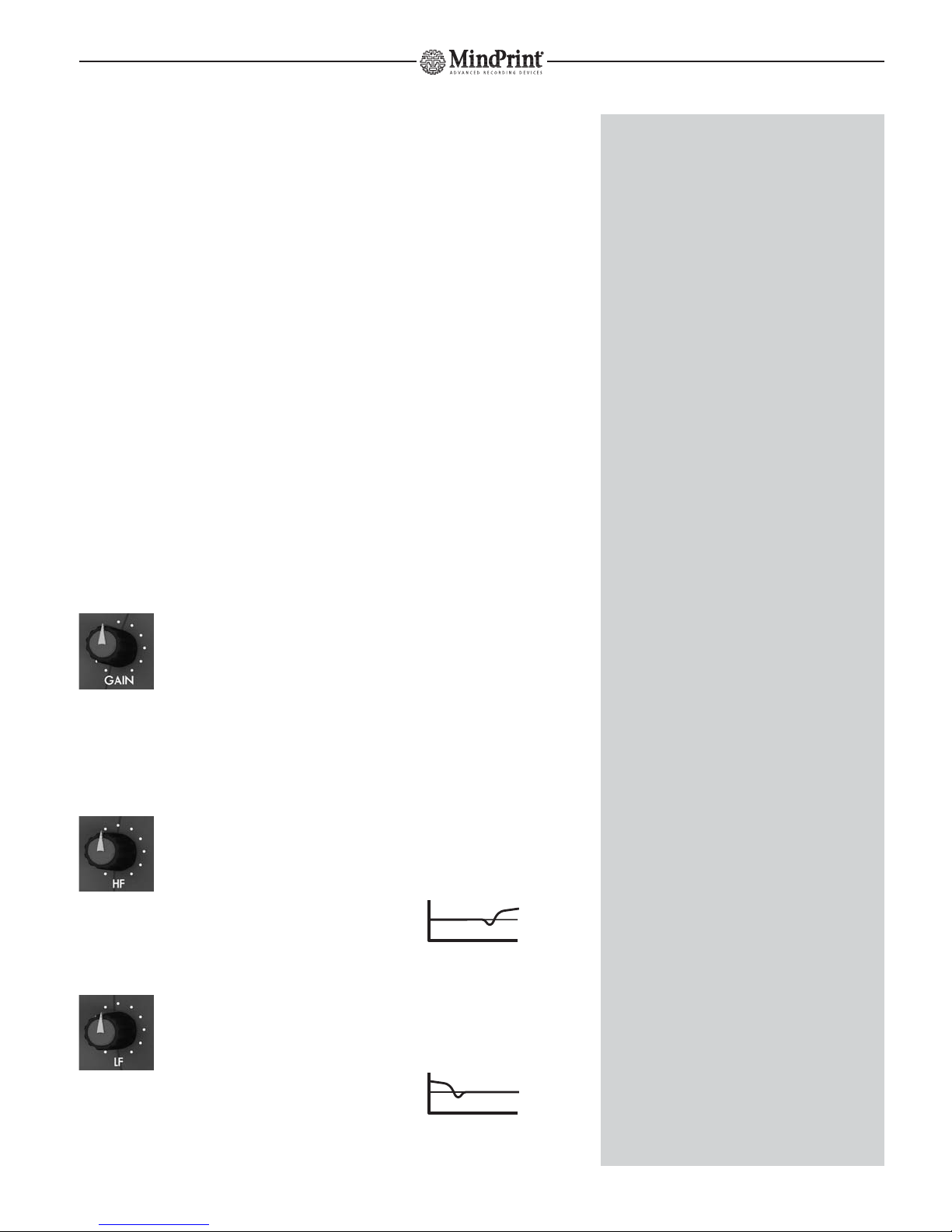
1.1 GAIN
This knob controls the amount of increase in microphones’
and instruments’ audio signal strength. Use this knob to
adjust the level for the microphone/instrument patched into the T.R.I.O™’s
channel strip.
Control range for microphones: -56 dB to +4 dB
Control range for instruments: -40 dB to +14 dB
1.2 HF
Twist this knob to adjust the amount of treble in the signal.
Characteristic: Chebyshev type high shelving filter
(Vintage dip-before-boost design)
Corner frequency: 7.5 kHz
Control range: +/- 12 dB
1.3 LF
Twist this knob to adjust the amount of bass frequencies in
the signal.
Characteristic: Chebyshev type low shelving filter
Corner frequency: 100 Hz
Control range: +/- 12 dB
8
MindPrint
®
T.R.I.O.
THE ONBOARD CHANNEL STRIP
The MIC/INSTR. input is more than merely a preamp circuit.
It comprises a full-fledged mixer channel strip offering hip
features like low cut, EQ and a compressor. It lets you process
the frequencies and dynamics of a signal before recording it.
xSwitch phantom power on only for microphones that
require it. Never feed power to unbalanced and ribbon
microphones! Do not connect line level devices to the
microphone input - this can damage T.R.I.O™.
gThe microphone input is automatically disabled when a
plug is inserted into the INSTRUMENT IN jack. This means
that for the sake of convenience, you can opt to leave a
microphone cord connected to MIC input.
INPUT SENSITIVITY
Designed to handle instrument levels, the instrument input
accepts guitar and bass signals directly. With an impedance
of 1 M-ohm, it does not load instrument’s pickups or degra-
de their sound. The technology that powers this input comes
courtesy of MindPrint®'s sister company Hughes & Kettner®,
whose guitar amp know-how we have to thank for this
input’s top-drawer audio quality.
PREAMPLIFICATION
Because the T.R.I.O™’s GAIN knob has such a formative
impact on incoming signals, it’s a good idea to be very fussy
about setting its level. If the input level is too high, the signal
may distort audibly. This kind of saturation is more than
annoying – it can render a great performance unusable. So,
proceed judiciously, dialing in settings so that signals peaks
never (or rarely and then only briefly) trigger the red LED.
REFRESHING SIGNALS
Most microphones tend to deliver fairly dark signals. You can
make signals such as vocals more articulate by boosting high
frequencies. The MIC/INSTR. Channel’s HF EQ is similar in
design to the circuitry found in coveted analog high-end
equalizers. Its Chebyshev-type filtering was borrowed from
the MindPrint®DTC: High mids are scooped slightly before
treble frequencies are boosted. This adds a silken sheen to
vocals while suppressing hissy-sounding sibilants. The LF
band of the MIC/INSTR. EQ also features Chebyshev filtering.

1.4 FAT
This is a soft knee-type compressor with auto gain make
up and program-dependent adjustment of time
constants. Though that sounds pretty complicated, handling is as easy as it
is effective: Far left setting = zero compression. Twist the knob clockwise to
dial in everything from slight compression to ultra fat signals. An LED
provides visual indication of compression amounts.
LED display:
green - no compression
orange - normal compression
red - strong compression
1.5 REC VOL.
Twist this knob to adjust the recording level of the MIC/INSTR.
signal sent to the DAW (independently of monitor volume).
When turned fully anti-clockwise, no signal is sent to the
DAW-interface.
1.6 MUTE
Silences the MIC/INSTR input. When this button is engaged,
its red LED lights up. MUTE affects the recording bus and
monitor bus.
1.7 48 V
Switches on +48V phantom power for the microphone input.
This button’s yellow LED lights up when power is activated.
Power is fed to the XLR port labeled MIC Input.
1.8 LOW CUT
Inserts a high-pass filter into the signal path; a yellow LED
indicates the given switching status. LOW CUT is located
directly behind the input stage in the signal path
Linkwitz-Riley characteristic
80Hz center frequency; 12dB/oct slope
9
MindPrint
®
T.R.I.O.
SIGNAL COMPRESSION
As first impressions go, the FAT knob may not bowl you ever, but it puts
a bona fide analog compressor at your fingertips. And though it brings
considerable sound-shaping power to the T.R.I.O™, it handles very easi-
ly. It literally lets you dial in great-sounding results for all micro-
phone/instrument signals at the twist of your wrist.
yREC VOL. determines the level of the signal recorded to the DAW,
and not the monitoring level. Adjust the monitoring level using the
MIC/INSTR. knob in the monitor section.
yThe analog VOL. REC level depends on the setting of a trim knob
on the bottom panel of the device with the wordy name DAW
INTERFACE ANALOG OUT LEVEL ADJUST (see 8.1 to learn more).
gMUTE comes in handy when you want to silence the mike during a
break or swap instruments.
gTRIO is the perfect sidekick for laptop-based audio presentations
with a headset microphone. To conveniently switch off the micro-
phone during breaks, simply hit the MUTE button.
PHANTOM POWER
Equipped with a robust wall wart, T.R.I.O is able to provide 48 V phan-
tom power that is stable enough to satisfy the demanding requirements
of high-quality capacitor microphones.
yMost condenser microphones will work with less than 48 volts.
However, any reduction in voltage lowers the peak gain level and
degrades sound quality.
yLOW CUT attenuates bass frequencies. This feature serves to filter
out low-frequency noise, for example, footsteps or popping noises
associated with close-miking vocals.
ENGLISH

1.9 INSERT
Connecting signal sources: To insert external processors
into the MIC/INSTR. circuit, connect them to the SEND and
RETURN jacks located on the rear panel.
Handling: When a plug is inserted into the RETURN jack,
T.R.I.O™ automatically injects the incoming signal into the
signal path. The SEND jack is permanently enabled; use it as an additional
signal tap, if you wish.
2. Stereo Line Input
Connect line level devices (such as keyboards, line mixers or drum compu-
ters) to the LINE input. Equipped with a two-band EQ, it may be configured
for both mono and stereo signals. If a source signal is patched into the
L/MONO jack only, it is automatically distributed to both channels.
Connecting signal sources:
Patch line level signals into the two mono 6.3 mm (1/4“) jacks on the rear
panel. Use the four-way DIP switch on the bottom panel of the device to
configure recording and monitor routing busses. See 10.1 to learn more
about this.
2.1 L/MONO
This jack accepts the left channel of a stereo signal or
channel 1 of any line source.
2.2 R
This jack accepts the right channel of a stereo signal or
channel 2 of any line source.
Bedienung:
2.3 HF
Twist this knob to adjust the Line signal’s treble amount.
Characteristic: Chebyshev type high shelving filter
Corner frequency: 9 kHz
Control range: +/- 12 dB
10
MindPrint
®
T.R.I.O.
gThe INSERT SEND may also be employed as an aux send, for exam-
ple, to address an external reverb unit.
gWhat’s more, you can connect a tuning device to INSERT SEND. This
way, an instrument’s tuning can be checked and adjusted on the fly
without unplugging it.
gThe signal of an external device (for instance, EN-VOICE®) may be
patched into INSERT RETURN. Because INSERT RETURN is located
post EQ/compressor, this option lets you bypass the T.R.I.O™‘s
input stage and EQ/compressor. The external signal is routed direc-
tly to the A/D converter and into the monitor section.
yThe term “routing" is studio-speak for the process of assigning
signals to different destinations. In other words, routing is the
process of mapping a signal from, say, a microphone via a circuit
such as input 1 or input 2 to a target such as your recording
software.
yConnect line level devices equipped with a single output (mono)
to the LEFT/MONO jack. Then the same signal is on both channels
of the Line input.

2.4 LF
Twist this knob to adjust the Line signal’s bass amount.
Characteristic: Low shelving filter
Corner frequency: 120 Hz
Control range: +/- 12 dB
2.5 REC VOL.
Twist this knob to adjust the level of the Line signal recorded
to the DAW (independently of monitor volume).
When turned fully anti-clockwise, no signal is sent to the
DAW-interface
2.6 MUTE
Silences the MIC/INSTR input. When this button is engaged,
its red LED lights up. MUTE affects both the recording buss
and monitor buss.
11
MindPrint
®
T.R.I.O.
REMINDER
REC VOL. determines the level of the signal recorded to the DAW, and
not the monitoring level. Adjust the monitoring level using the
MIC/INSTR. knob in the monitor section.
The analog VOL. REC level depends on the setting of the DAW INTER-
FACE ANALOG OUT LEVEL ADJUST trim knob on the bottom panel of
the device (see 8.4 to learn more).
gMUTE is a convenient tool for instantly silencing a keyboard
connected to the LINE input if you want to bypass its sound
generator and use its keys to play a VST instrument.
ENGLISH
3. ZERO LATENCY
MONITOR VOLUMES
In this section, you can route input signals directly to the monitor buss for
the purpose of latency-free monitoring. A dip switch on the bottom panel
of the device configures monitor routing busses. See 10.2 to learn more.
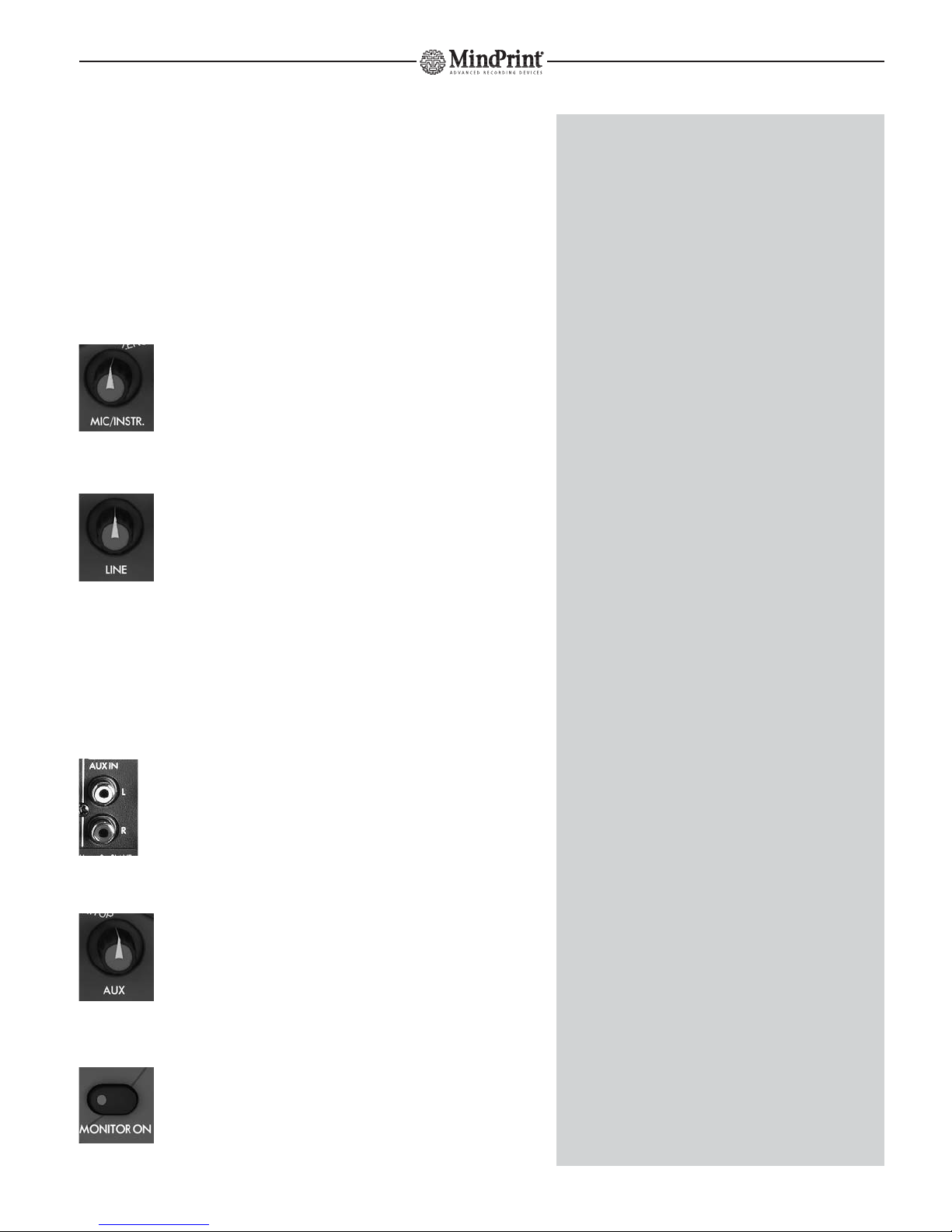
3.1 MIC/INSTR.
Twist this knob to adjust the MIC/INSTR. channel’s monitor
level. The signal is tapped post equalizer/compressor.
3.2 LINE
Twist this knob to adjust the Line channel’s monitor level.
The signal is tapped post equalizer.
3.3 AUX Input
Offering an ancillary stereo feed, the AUX input serves to connect consumer
level devices (such as CD and minidisk players). This signal is routed to the
monitor section.
Connecting signal sources:
Patch consumer level devices into the two LEFT and RIGHT RCA
connector ports on the rear panel.
Handling:
AUX:
Twist this knob to adjust the level of signals sent from the
AUX inputs to the monitor section.
3.4 MONITOR ON
Routes the input section’s signals as well as signals sent from the
AUX input to the monitor buss. The LED on the button lights up
to indicate MONITOR ON is active.
12
MindPrint
®
T.R.I.O.
ZERO LATENCY MONITORING
When recording to a digital medium, there is a certain amount of
latency inherent in the recorded signal. This delay is due to the time it
takes to convert the signal from analog to digital when it is patched
into the computer and vice versa when it comes back out. You can well
imagine the annoyance this causes musicians and vocalists. So can we,
which is why endowed T.R.I.O™ with a very practical DIRECT
MONITORING section.
A classic case of a fancy name for a straightforward feature, the ZERO
LATENCY MONITORING section lets you hear input signals without
delay because they are routed directly to the outputs rather than to the
computer and back via the DAW INTERFACE.
We recommend that you configure your recording software so that the
recorded signal is not routed out via the DAW’s outputs (INPUT
MONITORING = OFF ).
yThe AUX inputs’ signal is sent to the monitoring section only, and
cannot be recorded. The reasoning here is that the most common
signal source connected to an aux input is a CD player. If you want
to load a CD’s audio tracks to your computer, the more convenient
option is to use the computer’s CD-ROM disk drive.
yYou can connect other sources to the AUX input, for instance, a
reverb unit whose dry signal is provided via INSERT SEND. Thus you
can offer the vocalist some "working" reverb. Though the vocalist
hears the wet signal over the headphones, the actual vocal track is
recorded dry, that is, without reverb.
gThe AUX input is also a cool tool for tweaking T.R.I.O™’s master
level. Simply connect a CD player and adjust the AUX knob so that
the red output LEDs illuminate briefly and intermittently. (Some-
where around 12 o’clock, depending on the CD player’s level.) Use
this level as a reference for the monitor volume.
gWant to make A/B comparisons to a reference CD? Simply switch
back and forth between DAW ON and MONITOR ON to compare
the DAW’s signal to the reference CD’s signal.

3.5 DAW ON
Routes the incoming signal from the DAW to the monitor
buss. The LED on the button lights up to indicate DAW ON
is active.
4. Monitor Management Section
This section lets you access a blend of monitor mix and DAW return signal,
adjust monitor volume, select monitor outputs and connect a DAT/MD
recorder to record reference or backup tracks.
4.1 VOLUME
Twist this knob to adjust the master volume of the
SPEAKERS A, B and C monitor outputs. Level is equal on
all three outputs, SPEAKERS B output can be fine-
trimmed, see 4.5 to learn more
4.2 SPEAKERS A, B and C
Connections:
On the rear panel you’ll find three stereo outputs
for connecting monitor speakers or other amplifi-
cation systems. Output A (two 6.3 mm (1/4“)
mono jacks) serves to connect the first-choice
monitor speakers; output B (a pair of RCA
connectors) serves to connect an alternative
monitor pair. Output C (a pair of RCA connectors) serves to connect a
subwoofer or a third pair of monitors.
Handling:
SPEAKERS A, B, C
Sends the monitor signal to the selected outputs.
The LED on the button lights up to indicate the
given output is active. You can opt to address
several pairs of speakers simultaneously.
13
MindPrint
®
T.R.I.O.
xIn most scenarios, T.R.I.O™ is connected directly to active speakers
or power amps that are able to put to painfully high volume levels.
Do your hearing and your speakers the favor of always exercising
utmost caution when twisting the VOLUME knob. When in doubt,
roll back the VOLUME knob rather than cranking it wide open.
yThe VOLUME knob is of extra big size making it easy to be
accessed even in stress situations.
gIf you own a pair of speakers and a subwoofer, you can connect
the two satellites to SPEAKERS A and the subwoofer to SPEAKERS B
or C. This lets you address the speakers and subwoofer separately
and easily switch the latter off whenever you wish.
yWe opted to pass on a MUTE button for the simple reason that
you can enjoy the same functionality (silencing speakers) by simply
engaging the SPEAKER A/B/C buttons or turning down the
volume!
ENGLISH
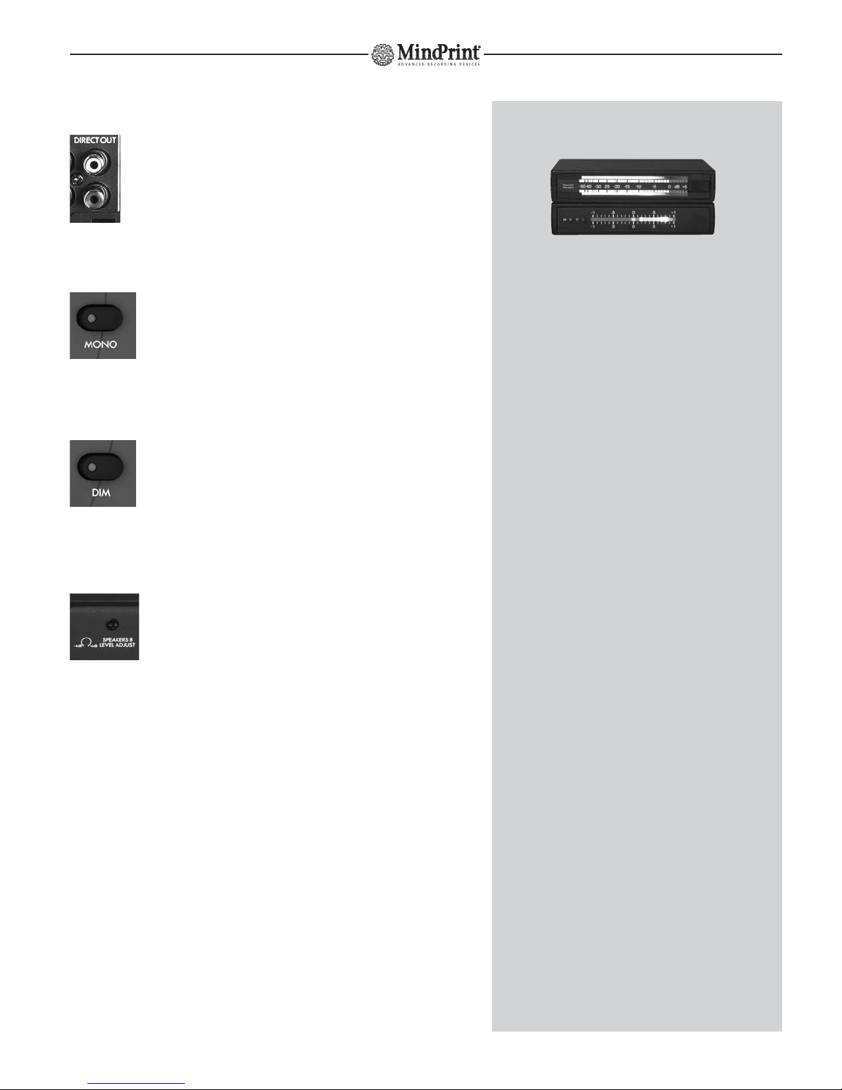
4.3 DIRECT OUT
You have a fourth stereo output at out disposal with DIRECT
OUT. This signal is tapped pre VOLUME knob (in contrast to the
SPEAKER A/B/C outputs), which means its level is not adjustable.
4.4 MONO
Press this button to blend the left and right signals and crea-
te a mono signal. When engaged, it affects all monitor and
headphones outputs. The LED on the button lights up to
indicate MONO is active.
4.5 DIM
Press the DIM button to cut the master volume of the moni-
tor outputs by 20 dB. This affects the speaker outputs only,
and not the DIRECT OUT and PHONES circuits.
4.6 SPEAKERS B LEVEL ADJUST
This stereo knob on the bottom panel of the T.R.I.O™ serves
to fine-tune the SPEAKER B output’s level.
Control range: - 4 dB at the far left position, unity gain at 12 o’clock,
+ 6 dB at the far right
14
MindPrint
®
T.R.I.O.
yYou can also use DIRECT OUT to connect meters such as peak level
or correlation indicators.
yIf you decide to employ T.R.I.O™ at gigs, you can use to DIRECT
OUTs to route the signal to the FOH mixer, and control your own
monitor mix via SPEAKER A/B/C.
gThe MONO function serves to check mono compatibility. This is a
nifty tool for detecting phase cancellations caused by reversed
polarity in cords/connectors, poorly chosen modulation effect set-
tings or extreme stereo processing operations, all of which may not
be clearly audible in a stereo soundscape.
ySome vocalists don’t like to hear a big stereo spread when tracking
their parts. In this event, simply press MONO, then the vocalist will
no longer be irritated by a shaker sweeping across the stereo
soundscape or a guitar part panned hard to the left edge.
gMany active monitors are very sensitive so that even low MONITOR
LEVEL settings elicit high volume levels. The DIM button cuts the
output level, enabling you to fine-tune levels with greater
precision and enjoy a wide VOLUME knob control range even at
very low monitor volumes.
yMONO and DIM do not affect DIRECT OUT. Otherwise, this
circuit’s signal would be reduced to mono when you press MONO
and attenuated when you press DIM for monitoring purposes.
yThe SPEAKER B LEVEL ADJUST knob is helpful when you want to
balance the relative levels of two speaker pairs so that you’re dea-
ling with similar levels when A/Bing between speaker pairs.

5. Metering Section
L (Left Meter)
The left LED chain indicates the level of the signal assigned
to the left side.
R (Right Meter)
The right LED chain indicates the level of the signal assigned
to the right side.
5.1 METER SELECT
Assigns the level meter to input signals or monitor signals. A corresponding
LED lights up to indicate the assignment status.
INPUTS:
When set to this position, the left LED chain indicates
the MIC/INSTR channel’s input gain. In order to make
best recording level possible, the source signal for the meter is tapped direc-
tly behind the input stage. The right LED chain indicates the LINE channel’s
input gain. If the LINE signal is mono, the LED indicates its input gain. If the
signal is stereo, the LED indicates the mono composite’s input gain.
OUTPUTS:
When set to this position, the LED chains indicate the
composite level of the monitoring section (MONITOR
ON) and the DAW return (DAW ON) signals. The source signal for the meter
is tapped pre OUTPUT VOLUME knob. In other words, it indicates the level
of the signal routed to DIRECT OUT.
15
MindPrint
®
T.R.I.O.
THE RIGHT INPUT LEVEL
The red level LEDs illuminate at a fairly low peak level of 1 dB. The
signal is not necessarily saturated if they light up briefly. However, it
certainly is in the red zone and on the brink of overloading the input.
Your best bet is to adjust the gain so the red LEDs light up from time
to time.
yIf a high-level signal is sent from DAW ON and signals are played
back via the MONITOR ON section, the LED meters may well lunge
into the red zone because signal levels add up. T.R.I.O™ has plenty
of headroom to handle saturated signals such as these without
giving cause to worry about audible distortion.
yWhen set to INPUTS, the LED chains do not indicate the levels of
the signal recorded to the DAW. Instead, they offer a view of
MIC/INSTR. and LINE input levels. In other words, the VOL. REC
knob’s setting has no influence on T.R.I.O™’s level meter.
The reasoning here this is that levels tend to
vary depending on the given DAW hard-
ware/software, and level matching will differ
accordingly. All popular recording
applications feature very precise digital input
level meters. This means you can easily view
and adjust the level of the signal sent to the
DAW using your recording software’s level
meter.
xWhen set to INPUTS, only the right LED chain indicates the Line
input signal level, even if you’re dealing with a stereo signal. Why?
Because if you’re recording to multiple channels, this lets you
monitor the input levels of the MIC/INSTR. channels (on the left
LED chain) and the LINE channels (L+R on the right LED chain)
simultaneously.
ENGLISH

6. Headphones Section
Connections:
Connect standard headphones to the two stereo 6.3 mm (1/4“) jacks on the
rear panel. The two headphones amps are equipped with plenty of power
to drive even weaker headphones and deliver enough volume to enable
satisfactory monitoring.
Handling:
6.1 PHONES A
Twist this knob to adjust the first headphones output’s
volume.
6.2 PHONES B
Twist this knob to adjust the second headphones output’s
volume.
16
MindPrint
®
T.R.I.O.
xWe strongly suggest that you always employ headphones with an
impedance greater than 30 ohms. Lower impedances or a short
circuit caused by mono jack plugs can do permanent damage to
T.R.I.O™’s headphones outputs.
xDo not connect headphones to SPEAKERS A jacks because this can
harm T.R.I.O™.
ySavvy recordists may want to use PHONES outputs for a purpose
other than intended – to connect further speakers via Y adapters
(stereo jack on one end; two mono jacks on the other), to drive
speakers sited in the studio’s recording room. This lets you control
these speakers’ volume separately and communicate with
musicians using the TALKBACK microphone. But whatever you do,
never insert mono plugs into the PHONES jack.
yFor a happier and more congenial recording experience, it’s a good
idea for the vocalist and producer to don the same model of head-
phones when tracking vocals.

7. Talkback Section
T.R.I.O™ comes with a full-fledged talkback section featuring a built-in talkback
microphone.
7.1 TA LKBACK
Push this button to activate the talkback microphone. The
signal is routed to the headphones outputs until you release
the button. The monitor signal sent to the headphones out-
puts is automatically cut by 12 dB.
7.2 TB VOLUME
Twist this knob to adjust the volume of signal the sent from
the built-in talkback microphone to the headphones busses.
7.3 TB MIC
The talkback microphone is sited midway between the
TALKBACK button and the TB VOLUME knob, below the
three little holes in the housing.
17
MindPrint
®
T.R.I.O.
g""Talkback" is the term used for a neat feature found on big studio
consoles that allows producers/engineers in the control room to
speak to the artist in the studio via a microphone built into the
console. To this end, the talkback microphone signal is sent to the
headphones busses.
yYou may have little reason to like the TALKBACK function now, but
you may learn to love it later when you discover your recording
mic capturing the rattling of your computer’s fan or other ambient
noise (the classic culprit being the creaking of chairs). In this event,
relocate the vocalist and microphone to a quiet room and commu-
nicate via TALKBACK.
gIn the heat of the moment, producers sometimes begin addressing
the vocalist before pressing the TALKBACK button. If vocalists can’t
hear the beginning of a sentence, they won’t understand you.
Misunderstanding breeds insecurity; an insecure artist can’t deliver
a compelling performance. So in the interests of capturing hap-
pening performances make a habit of pressing TALKBACK FIRST,
and then talking.
yYou’ll hear a soft “pong” sound when you press the TALKBACK
button. This not a malfunction. The TB microphone is extremely
sensitive; indeed, it’s so delicate it transmits the sound the button
engaging. Eventually, you’ll find this to be an advantage: the
"pong" signals to vocalists that words of wisdom are coming their
way! :o)
xDo not place objects on the TB microphone or push in the micro-
phone covering with pointed objects.
ENGLISH

8. DAW INTERFACE
Located on the T.R.I.O™’s rear panel is an interface that connects to the
DAW. Linking the T.R.I.O™ to the computer, this interface transports all audio
data to and from the DAW. You have analog and digital ports at your
disposal.
Connections:
Two pairs of RCA connectors for the inputs and the outputs, respectively,
provide analog access to the DAW. Adjust signal levels to match the levels of
the DAW using the TRIM knobs on the bottom panel of the device.
Two optical ports in TOSLINK format provide a digital link to the DAW.
8.1 ANALOG OUT L/R
Use the two RCA connectors on the rear panel to set up an
analog line to the DAW. The signals of the MIC/INSTR and LINE
busses are recorded to the DAW via these ports.
8.2 ANALOG OUTPUT LEVEL ADJUST
Twist this knob on the bottom panel of T.R.I.O™ to adjust
the level of recording signals sent to the DAW’s analog
inputs. The control range is -oo to +6dB (0 dB at the center
detent position).
8.3 ANALOG IN L/R
Use the two RCA connectors on the rear panel to return analog
signals from the DAW.
Signals sent from the DAW are routed to the monitor section via
these ports.
8.4 ANALOG INPUT LEVEL ADJUST
Twist this knob on the bottom panel of T.R.I.O™ to adjust
the level of signals playback sent from the DAW’s analog
outputs. Control range: -oo to +6 dB (0 dB at the center
detent position)
18
MindPrint
®
T.R.I.O.
yThe DAW interface has the job to carry the recording signals from
TRIO to the DAW inputs, and brings back the DAW outputs to TRIO.
The interface works in "full duplex", so you can record in the DAW
while simultaneously playing back the DAW outputs.
gAnalog and digital outputs may be used simultaneously. Case in
point: If you have set up a digital circuit to the DAW, you can use
the analog outputs to patch out recorded signals, say to back-up
tracks to a minidisk. You can use the same approach to set up an
aux send to an outboard signal processor.
gThe analog DAW INTERFACE outs may also be used as aux sends,
for example, to add makeshift “working“ reverb to recording
signals.
gDitto for analog and digital inputs. For instance, you could use the
DAW INTERFACE ANALOG INPUTS as an additional stereo in for
connecting a CD player or effect device. This increases the number
of simultaneously accessible analog inputs available on T.R.I.O™ to
one mono and three stereo ports.

9. DIGITAL-INTERFACE
T.R.I.O™ comes with a digital interface in optical S/PDIF format (TOSLINK)
that lets you integrate the device into a digital recording environment.
9.1 S/PDIF IN
The digital output of the DAW connects to this input via the
computer interface. The converted signal is sent directly to the
monitor buss.
9.2 S/PDIF OUT
This port connects to the DAW’s S/PDIF digital input.
The A-to-D converted signals of the MIC/INSTR. and LINE
busses are sent to this port.
9.3 SYNC LED
This LED lights up when the S/PDIF input receives a viable
digital signal.
Synchronization
Affording flexible connections to digital studio environments,
T.R.I.O™’s digital interface features a three-way selector
providing all the options you need to configure a digital
setup.
9.4 44,1/48:
This button (in combination with the neighboring "x2" button) determines
the sampling rate for T.R.I.O™ in stand-alone mode.
Position 1 selects 44.1 kHz.
When set to position 2, T.R.I.O™ runs on 48 kHz.
9.5 x1/x2 (= Double Sampling Rate)
When this button is set to position 1, the device operates on the frequency
determined by the neighboring 44.1/48 button’s setting. In position 2, the
device works with double the sampling rate defined by the 44.1/48 button;
that is, 88.2 kHz or 96 kHz.
19
MindPrint
®
T.R.I.O.
yDeveloped by SONY and Philips and standardized by the IEC in
1987, S/PDIF is designed for semiprofessional and home use.
Providing an unbalanced circuit, S/PDIF is today the de facto
standard worldwide.
S/P-DIF optical (TOSLINK)
The optical interface has some advantages over its electrical coaxial
counterpart:
• Special optical fiber cords rules out problems associated with using
the wrong cables.
• Many devices’ optical ADAT interfaces may be set to S/PDIF optical
format.
• Galvanic separation prevents ground loops and pickup of stray
interference.
• Optical is more common than coaxial.
yIf your DAW offers coaxial rather than optical S/PDIF ports, you’ll
find S/P-DIF optical-to-coaxial converters in well-stocked music
stores.
gThe SYNC LED tells you that a viable signal is patched into the
S/PDIF INPUT. If your setup isn’t working properly, this light helps
you narrow down the cause.
SYNCHRONIZATION
Once digital audio devices are connected, their internal clock frequen-
cies must be synchronized. To this end, one device acts as the master,
dictating the sampling rate and bit rate to the rest, which are called
slaves in this type of configuration. Symptoms such as popping noises
during recording are typical indications that devices aren’t in sync and
that settings require review.
SAMPLING RATE
The sampling rate is the frequency at which digital audio signals are
measured (sampled) at discrete points in time. In the case of an audio
CD, this is 44,100 times per second, which equals a frequency of
44.1 KHz. As a rule, the higher the selected sampling rate, the "better"
the audio signal quality; that is, the more accurately the original analog
signal is rendered.
Note that higher sampling rates require proportionately more memory.
xAs both TRIO and the DAW can be work in MASTER mode, audible
interferences might occur because both units use their own
frequency. An indication for this is e.g. when the DAW playback
signal sounds dull and muddy. In case of doubt please double
check the sync settings of both units and make sure there is one
MASTER and one SLAVE.
yT.R.I.O™’s digital interface processes audio at a resolution of up to
96kHz / 24bits.
ENGLISH

9.6 MASTER/SLAVE
In position 1, T.R.I.O.™ is the MASTER, and runs on the internally selected
sampling frequency. To ensure proper synchronization, the connected DAW
must be configured as "slave" or "external".
In position 2 (=SLAVE), T.R.I.O.™ automatically slaves to an incoming digital
signal once it has determined that this signal is viable. The device runs in
sync with the DAW’s sampling rate. The SYNC LED lights to indicate it is
receiving a viable digital signal.
10. RECORD/MONITOR
MODE SELECTOR
Located on the bottom panel of the T.R.I.OTM is
a miniature four-way DIP switch that serves to
configure recording and monitoring busses.
10.1 MIC/INSTR RECORD (1)
Activate this switch to send the left side (= channel 1 of the recording soft-
ware) of the MIC/INSTR. channel’s signal to the left and right sides of the
recording buss (signal is routed to both channels simultaneously).
10.2 MIC/INSTR. MONITOR (2)
Activate this switch to send the left side of the MIC/INSTR. channel’s signal
to the left and right sides (stereo center) of the monitor buss. This setting
applies to PHONES, DIRECT OUT and SPEAKERS.
10.3 LINE RECORD (3)
Activate this switch to send the right side (= channel 2 of recording soft-
ware; possibly the mono composite) of the LINE channel’s signal to the left
and right sides (stereo) of the recording buss.
10.4 LINE MONITOR (4)
Activate this switch to send the right side (possibly the mono composite) of
the LINE channel’s signal to the left and right sides (stereo) of the monitor
buss. This setting applies to PHONES, DIRECT OUT and SPEAKERS.
20
MindPrint
®
T.R.I.O.
yThe S/P-DIF interface offers separate digital input/output ports.
The advantage here is that this allows you to introduce other
devices into your DAW’s digital setup. For instance, you could
connect another device equipped with a digital output (say, a DI-
PORT for tracking with stereo microphones) to record to the DAW,
and use T.R.I.O™ for monitoring purposes only for the duration of
this little exercise in flexibility.
yThough T.R.I.O™ is a device with two input channels, the two
channels do not automatically equate to a stereo setup. In purely
stereo devices, channel 1 is always on the left; channel 2 is always on
the right. T.R.I.O™ is more flexible: You are free to route the mono as
well as the stereo channel to the DAW input of your choosing and to
determine to which side(s) of the headphones/speaker they are sent.
yIn the factory default configuration, all four switches are set to ON
= L/R. This means that the MIC/INSTR. signal as well as the LINE
signal are sent to the DAW’s input as well as to both sides of the
headphones/speaker circuits. This gives you flexible routing options
for both signals, for example, by simply arming the desired DAW
inputs.
yRECORD/MONITOR MODE SELECTOR settings apply to both the
headphones, the DIRECT OUT and the speaker outputs. Depending
on DIP switch settings, you may encounter some “interesting”
monitoring scenarios, for example, where the monitor signal is
audible on the left speaker only.
yThough the RECORD/MONITOR MODE SELECTOR may not mean
much to you now, it offers some very convenient options that you
will come to appreciate later: Say a guitarist wants to double a
previously recorded track: You can let him hear the canned track
on the left side of the headphones/speaker system and the live
recording signal on the right. Another example: Say you want to
record a guitar along with a stereo effect generated by a signal
processor. Simply set all switches to ON (=default) to receive a
signal where the guitar is centered and the effect signal is
rendered in true stereo.
Other manuals for T.R.I.O.
1
Table of contents
Languages:
Other MINDPRINT Recording Equipment manuals


