Mindsets PAC-1403 User manual

1
FM Radio
PAC-1403

2
Parts List
1 x Circuit board
1 x Battery snap
1 x Length of stranded wire
1 x Speaker
1 x 10K Potentiometer (linear)
1 x 10K Potentiometer (logarithmic)
Also required:
Soldering iron & solder.
The radio is supplied as a completely populated printed circuit board (PCB) that
requires only the addition of five external components: battery, loudspeaker,
tuning control, volume control and small aerial supplied within the pack. A
working radio can be assembled from the parts provided in this pack, but other
external components can be substituted to provide a choice of control functions
- and improved sound quality.
Designing and making a complete radio offers a huge range of fascinating and
potentially challenging design decisions and is a very practical vehicle for
teaching many of the principles involved in radio electronics and acoustics.
Introduction
NOTE: This radio is tuned by using a potentiometer and a varicap (whose
capacitance depends on voltage). This arrangement is cheaper and more
flexible than using a variable capacitor.
36.0
Dimensions given
in millimetres
3.216.0
3.0
40.0
3
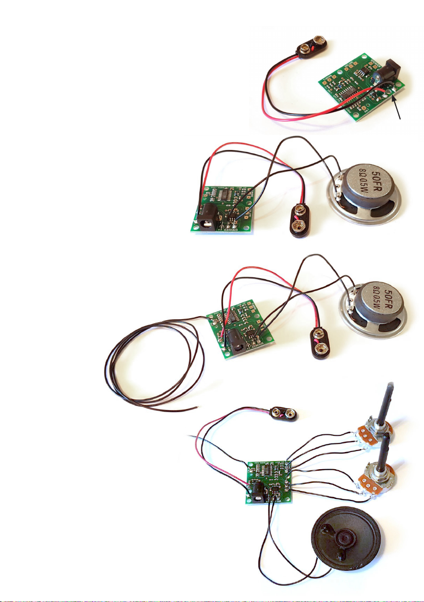
Step 2
Solder on the loudspeaker using
two lengths of stranded wire.
The loudspeaker can be
connected either way round.
Step 3
Solder on a length of approximately
0.5m stranded wire to act as an aerial.
A telescopic aerial can be attached
instead. This is supplied
separately.
Step 1
Solder on the battery snap leads - ensuring that
the red lead is connected to +ve on the PCB.
Optionally pass wires through strain relief holes
before soldering.
Step 4
Solder on the tuning and
volume control potentiometers
as shown using three lengths
of stranded wire for each. The
variable resistor marked ‘A’ is for
volume control and the one marked
‘B’ is for tuning.
strain relief
holes

4
Designed and supplied by:
Mindsets (UK) Ltd
01992 716 052
www.mindsetsonline.co.uk
© 2018 Mindsets (UK) Ltd
For each potentiometer, the two outer leads can be connected either way round,
but this will determine the direction of tuning and volume control when the
spindles are turned. It is essential that the centre lead goes to the centre connection
of each variable resistor.
Step 5
Check that all connections are correct and secure and then connect a battery.
We recommend 4 x AA batteries for best performance.
An Alkaline 9V PP3 battery can also be used.
It is important to note that the
loudspeaker needs a baffle. This is
normally provided by putting the
loudspeaker into an enclosure.
The difference in sound quality
and volume that this makes can be
demonstrated by listening to the
sound before and after hands are
cupped around the loudspeaker.
If the radio fails to work first time:
• Check that the batteries have been correctly inserted in the battery box (if used).
• Check on battery condition.
• Check for dry solder joints.
Optional components available from Mindsets:
• Telescopic aerial
• Switches for power
Generic principles and
guidelines for using
Maplins Electronics kits.
Prefix: C - Capacitors: ceramic,
electrolytic or polyester
Ceramic disk and polyester capacitors can
be identified by a numerical code. For
example 104 on a ceramic disk capacitor
indicates a capacitance of 100nF (or 0.1F).
See the assembly instructions for codes
relevant to your kit.
Electrolytic capacitors must be inserted the
correct way round. The longer leg is
positive and should be inserted into the
hole marked with a + symbol on the circuit
board. The shorter negative leg is usually
marked with a stripe
containing – symbols on
that side of the
capacitor.
Soldering
Use a soldering iron not more than 40W
power and ensure the tip is clean.
Apply a small amount of solder to tin the
tip.
Use the soldering iron to heat up both the
component leg and pad for about one
second.
While keeping the soldering iron in place
touch the end of the solder to the leg and
iron, as the solder melts move the solder
in ensuring it flows over the pad and
component leg making
a smooth joint.
Inserting components:
Axial components (like resistors and
diodes) need to have their legs bent by 90
degrees.
Insert component legs through the holes
indicated by the legend on the circuit
board. Be careful not to use too much force
on fragile components like ceramic
capacitors.
Bend legs slightly
apart to keep
component in
place when
turning over the
circuit board for
soldering.
Allow the solder to cool for a few seconds
then snip off the excess component leg
just above the solder joint.
104
R6
PRI 450
Periodically clean the tip on a damp
sponge.
Re-tin the tip before powering off your
soldering iron.
Watch out for 'dry' joints, where the solder
has not adhered properly to the leg or to
the pad (see below).
Start by looking at the parts list which is
printed on the cardboard insert in the pack-
aging of the kit. There are three columns,
the first of which specifies the part number.
The same part number is printed on the cir-
cuit board, showing where that part (or com-
ponent) should be inserted. Also, the out-
line associated with the part number gives
you a hint to the shape and orientation of
the component. The alphabetical prefix of
each part number indicates what type of
component it is. For example, R11 has the
prefix R, indicating it is a resistor. Each com-
ponent type can usually come in different
values. It is important to use the prefix to go
to the relevant section of this booklet for
advice on identifying the correct part.
Work your way down the list: identifying
each part; check to see if there are any addi-
tional hints for that part (found under the
parts list); insert it into the correct location
on the circuit board; and solder the compo-
nent in place (see the sections on inserting
and soldering components).
Prefix: R - Resistor or variable resistor
To select the correct value, check against the
colour code in the parts list. Use a multimeter
to check the resistance if you are unsure (be
careful when checking resistors more than a
few kilohms, as the resistance of your skin
could alter the reading).
Potentiometers (variable resistors) have their
value printed on them
Good solder joints
Dry solder joints
(No connection)
Unbaffled
Speaker
Baffled
Speaker
Table of contents


